Sony STR-SE501: Understanding the Multi-Channel Surround Displays
Understanding the Multi-Channel Surround Displays: Sony STR-SE501
Table of contents
- WARNING Precautions
- About This Manual T ABLE OF CONTENTS Additional Information
- Hooking Up the Components Unpacking
- Antenna Hookups
- Audio Component Hookups
- Video Component Hookups
- Digital Component Hookups
- 5.1CH Input Hookups
- Other Hookups
- CONTROL A1 hookup (STR-DE545 and STR-SE501 only) AUX AUDIO IN hookup Connecting the AC power cord
- Hooking Up and Setting Up the Speaker System
- Speaker System Hookup
- Speaker System Hookup
- Performing Initial Setup Operations
- Multi Channel Surround Setup
- Center speaker size ( Rear speaker size (
- Multi Channel Surround Setup
- Adjusting the speaker volume
- Before turning on the receiver Checking the connections Before You Use Your Receiver Multi Channel Surround Setup
- There is no sound no matter which component is selected. No sound is heard from one of the front speakers.
- Front Panel Parts Descriptions Location of Parts and Basic Operations ? 1 switch Function buttons
- INPUT MODE button
- Front Panel Parts Description
- 25
- Front Panel Parts Description
- Enjoying Surround Sound
- Selecting a Sound Field
- Sound field information
- Use the buttons on the front panel to operate the following modes Selecting a Sound Field
- Understanding the Multi-Channel Surround Displays
- Understanding the Multi-Channel Surround Displays
- Customizing Sound Fields
- Adjusting the level parameters Customizing Sound Fields
- Adjusting the bass/treble Resetting customized sound fields to the factory settings
- Customizing Sound Fields Adjustable parameters for each sound field
- Receiving Broadcasts
- Brief descriptions of buttons used to receive broadcasts
- Storing FM Stations Automatically Direct Tuning
- Preset Tuning Presetting radio stations Automatic Tuning
- Tuning to preset stations Receiving RDS broadcasts Displaying the RDS Information Using the Radio Data System (RDS)
- Using the Radio Data System (RDS) Monitoring traffic, news, or information programmes (EON) Locating a station by programme type
- Description of program types
- Other Operations
- Recording Naming Preset Stations and Program Sources
- Recording on a video tape Using the Sleep Timer Recording
- Adjustment Using the SET UP Button
- Troubleshooting Additional Information
- Reference sections for clearing the receiver’s memory
- Specifications Amplifier section
- FM tuner section AM tuner section Video section General
- Glossary
- Settings Using SUR, LEVEL, BASS/TREBLE, and SET UP buttons
- Remote Button Description (STR-DE445 only)
- Changing the factory setting of a function button
- Remote Button Description (STR-DE445 only)
- Index
32
GB
Enjoying Sur
round Sound
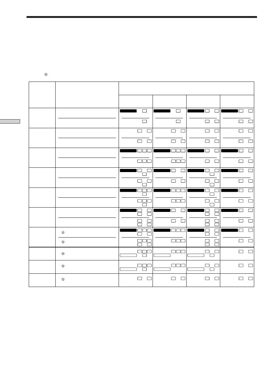
Source sound displays
The letters (L, C, R, etc.) indicate the source sound. The box around the letters varies to show how the receiver downmixes
the source sound (based on the speakers settings). When using music sound modes such as HALL or JAZZ CLUB, the
receiver adds reverberation based on the source sound.
The following table shows how the indicators light up when using AUTO FORMAT DECODING mode.
Although the table below shows almost all of the configurations available from multi channel surround signals, the ones
marked “ ” are the most common.
* Signals with Dolby surround encoded flag OFF
** Signals with Dolby surround encoded flag ON
*** The sampling rate is displayed.
Notes
• The receiver performs Pro Logic decoding and the display conforms to 2/0** when using the following movie sound modes with 2/0*
or STEREO PCM format signals. (C. STUDIO A, B, C, V. MULTI, and V. SEMI-M.)
• When using music sound modes such as HALL or JAZZ CLUB with standard audio formats e.g., PCM, the receiver creates rear
signals from the front L and R signals. In this case, sound is output from the rear speakers, but output channel indicators for the rear
speakers do not light.
Understanding the Multi-Channel Surround Displays
1/0
2/0*
3/0
2/1
3/1
2/2
3/2
2/0**
DOLBY DIGITAL [1/0]
DTS [1/0]
DOLBY PROLOGIC
PCM XX kHz***
DIGITAL
a
C
C
DOLBY DIGITAL [2/0]
DTS [2/0]
DOLBY DIGITAL [3/0]
DTS [3/0]
DOLBY DIGITAL [2/1]
DTS [2/1]
DOLBY DIGITAL [3/1]
DTS [3/1]
DOLBY DIGITAL [2/2]
DTS [2/2]
DOLBY DIGITAL [3/2]
DTS [3/2]
DOLBY DIGITAL [2/0]
DIGITAL
a
C
dts
C
DIGITAL
a
C
dts
C
DIGITAL
a
C
dts
C
DIGITAL
a
L
C
R
L
C
R
DIGITAL
a
L
C
R
L
C
R
DIGITAL
a
L
C
R
L
C
R
DIGITAL
a
L
C
R
L
C
R
L
R
L
R
L
R
dts
L
R
DIGITAL
a
L
S
R
L
S
R
DIGITAL
a
L
S
R
L
S
R
DIGITAL
a
L
S
R
L
S
R
DIGITAL
a
L
S
R
L
S
R
DIGITAL
a
L
C
S
R
L
C
S
R
DIGITAL
a
L
C
S
R
L
C
S
R
DIGITAL
a
L
C
S
R
L
C
S
R
DIGITAL
a
L
C
S
R
L
C
S
R
DIGITAL
a
L
LS
R
RS
L
LS
R
RS
DIGITAL
a
L
LS
R
RS
L
LS
R
RS
DIGITAL
a
L
LS
R
RS
L
LS
R
RS
DIGITAL
a
L
LS
R
RS
L
LS
R
RS
DIGITAL
a
L
LS
C
R
RS
L
LS
C
R
RS
DIGITAL
a
L
LS
C
R
RS
L
LS
C
R
RS
DIGITAL
a
L
LS
C
R
RS
L
LS
C
R
RS
DIGITAL
a
L
LS
C
R
RS
L
LS
C
R
RS
PRO LOGIC
L
C
S
R
PRO LOGIC
L
C
S
R
PRO LOGIC
L
C
S
R
PRO LOGIC
L
C
S
R
PRO LOGIC
L
C
S
R
PRO LOGIC
L
C
S
R
PRO LOGIC
L
C
S
R
PRO LOGIC
L
C
S
R
L
R
L
R
L
R
L
R
L
R
L
R
L
R
L
R
dts
Recording
Format
(Front/Rear)
Input Channel Display
Source sound and Output Channel Display
All speakers
present
Rear speakers
absent
Center speaker
absent
Rear/center
speakers absent
dts
dts
dts
dts
dts
dts
dts
dts
dts
dts
dts
dts
dts
dts
dts
dts
dts
dts
dts
dts
dts
dts
dts


