Sony HVL-MT24AM: instruction
Class: Video Audio Photo Equipment
Type:
Manual for Sony HVL-MT24AM
Table of contents
2-889-493-21 (1)
Macro Twin Flash Kit
Operating Instructions
Manual de instruções
Manual de instrucciones
Bruksanvisning
HVL-MT24AM
Printed on 70% or more recycled paper
using VOC (Volatile Organic
© 2006 Sony Corporation Printed in Japan
Compound)-free vegetable oil based ink.
HVL-MT24AM_RU 2-889-493-21 (1)HVL-MT24AM_RU 2-889-493-21 (1)

English
Before operating the product, please read this manual thoroughly and retain it for
future reference.
WARNING
To reduce re or shock hazard, do not expose the unit to rain or moisture.
Tape over lithium battery contacts to avoid short-circuit when disposing of
batteries, and follow local regulations for battery disposal.
Keep batteries or things that could be swallowed away from young children.
Contact a doctor immediately if an object is swallowed.
Immediately remove the batteries and discontinue use if...
the product is dropped or subjected to an impact in which the interior is
exposed.
the product emits a strange smell, heat, or smoke.
Do not disassemble. Electric shock may occur if a high voltage circuit inside the
product is touched.
IMPORTANT SAFETY
INSTRUCTIONS
When using your photographic equipment, basic safety
precautions should always be followed, including the
following:
Read and understand all instructions before using.
Close supervision is necessary when any appliance is used
by or near children. Do not leave appliance unattended
while in use.
Care must be taken as burns can occur from touching hot
parts.
2
HVL-MT24AM_GB 2-889-493-01 (1)
Do not operate appliance with a damaged cord or if the
appliance has been dropped or damaged- until it has been
examined by a qualied serviceman.
Let appliance cool completely before putting away. Loop
cord loosely around appliance when storing.
To reduce the risk of electric shock, do not immerse this
appliance in water or other liquids.
To reduce the risk of electric shock, do not disassemble
this appliance, but take it to a qualied serviceman when
service or repair work is required. Incorrect reassembly
can cause electric shock when the appliance is used
subsequently.
e use of an accessory attachment not recommended by
the manufacturer may cause a risk of re, electric shock, or
injury to persons.
Batteries may become hot or explode due to improper use.
Use only the batteries specied in this instruction manual.
Do not install the batteries with the polarity (+/-) reversed.
Do not subject batteries to re or high temperatures.
Do not attempt to recharge (except for rechargeable
batteries), short or disassemble.
Do not mix, batteries of dierent types, brands or ages.
SAVE THESE INSTRUCTIONS
CAUTION
Do not touch the ashtube during operation, it may become hot
when the ash res.
3
HVL-MT24AM_GB 2-889-493-01 (1)
For customers in Europe
Disposal of Old Electrical & Electronic Equipment (Applicable
in the European Union and other European countries with
separate collection systems)
is symbol on the product or on its packaging indicates that this
product shall not be treated as household waste. Instead it shall
be handed over to the applicable collection point for the recycling
of electrical and electronic equipment. By ensuring this product
is disposed of correctly, you will help prevent potential negative
consequences for the environment and human health, which
could otherwise be caused by inappropriate waste handling of this
product. e recycling of materials will help to conserve natural
resources. For more detailed information about recycling of this
product, please contact your local Civic Oce, your household
waste disposal service or the shop where you purchased the
product.
For the customers in the U.S.A.
CAUTION
You are cautioned that any changes or modications not expressly approved in this
manual could void your authority to operate this equipment.
NOTE:
is equipment has been tested and found to comply with the limits for a Class B
digital device, pursuant to Part 15 of the FCC Rules.
ese limits are designed to provide reasonable protection against harmful
interference in a residential installation.
is equipment generates, uses, and can radiate radio frequency energy and, if
not installed and used in accordance with the instructions, may cause harmful
interference to radio communications.
However, there is no guarantee that interference will not occur in a particular
installation. If this equipment does cause harmful interference to radio or television
reception, which can be determined by turning the equipment o and on, the
user is encouraged to try to correct the interference by one or more of following
measures:
– Reorient or relocate the receiving antenna.
– Increase the separation between the equipment and receiver.
– Connect the equipment into an outlet on a circuit dierent from that to which
the receiver is connected.
– Consult the dealer or an experienced radio/TV technician for help.
4
HVL-MT24AM_GB 2-889-493-01 (1)

Table of contents
Features .......................................... 6
Additional
Name of parts ................................ 7
Information
Examples of macro twin ash
photography ................................ 51
Preparations
Inserting batteries ....................... 11
Aperture range graph ................. 54
Attachment and removal of the
Compatibility with other
macro ash controller ................ 13
products ....................................... 56
Attaching the macro twin ash
Notes on use ................................ 57
....................................................... 14
Maintenance ................................ 58
Auto power ON/OFF ................. 21
Specications............................... 59
Basics
Basic ash modes
(A mode/M mode) ..................... 22
Program auto ash (e basics)
....................................................... 30
Detailed operations
Manual ash (M) ........................ 32
Test ash ...................................... 40
Modeling ash ............................ 41
Wide panel ................................... 42
Diuser ........................................ 44
Custom setting ............................ 48
5
HVL-MT24AM_GB 2-889-493-01 (1)

Before use
For details, refer to the operating instructions supplied with your camera.
This flash is not dust-proof, splash-proof or waterproof.
Do not place this flash in the following locations
Regardless of whether this unit is in use or in storage, do not place it in any of the
following locations. Doing so may lead to a malfunction.
Placing this ash in locations subject to direct sunlight such as on dashboards or
near a heater may cause this unit to deform or malfunction.
Locations with excessive vibration
Locations with strong electromagnetism
Locations with excessive sand
In locations such as the seashore and other sandy areas or where dust clouds
occur, protect the unit from sand and dust.
is may lead to a malfunction.
Features
e macro twin ash kit provides exible lighting for macro nature photography. It
is ideal for close-up photography of owers, insects, small objects, and so on.
Freedom to change the attachment position and angle of the ashtube enables
more expressive photography.
Attaching two-length adjustable arms between the twin ash units and holders
makes it possible to change the lighting for high magnication close-up
photography.
Using the supplied diuser enables soer lighting.
e supplied wide panel expands ash coverage to a focal length of 24 mm.
Modeling ash function can check shadows before photographing.
6
HVL-MT24AM_GB 2-889-493-01 (1)
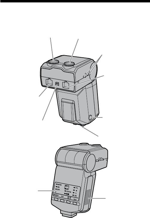
Name of parts
Macro Flash Controller
Manual-flash-control dial
Manual-flash-control dial
(Twin flash A) (33)
(Twin flash B) (33)
Reel-attachment
points (18)
Twin-flash-cord socket
(Twin flash A) (15) *
Twin-flash-cord socket
(Twin flash B) (15) *
Mounting-foot-release
Twin-flash-cord release
button (13)
button (16)
Mounting foot
Control panel (8)
Battery-chamber
door (11)
* Do not touch directly.
7
HVL-MT24AM_GB 2-889-493-01 (1)
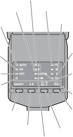
Control Panel
Twin flash A lamp (24)
Twin flash B lamp (24)
TTL lamp (32)
M (manual-flash-control)
lamp (32)
Auto lamp (31)
Test-flash lamp
(40)
Flash-ON lamp (21)
Modeling-flash
Flash-OFF lamp (21)
lamp (41)
Flash-ready lamp (25)
Custom lamp
(50)
Flash ON/OFF button (21)
TEST button (Test/
modeling flash button)
(40, 41)
A-B button (Twin-flash A-B
TTL/M/Test button (TTL/M/
selection button) (24)
Test/Modeling flash mode
Low-battery
button) (32)
lamp (12)
8
HVL-MT24AM_GB 2-889-493-01 (1)
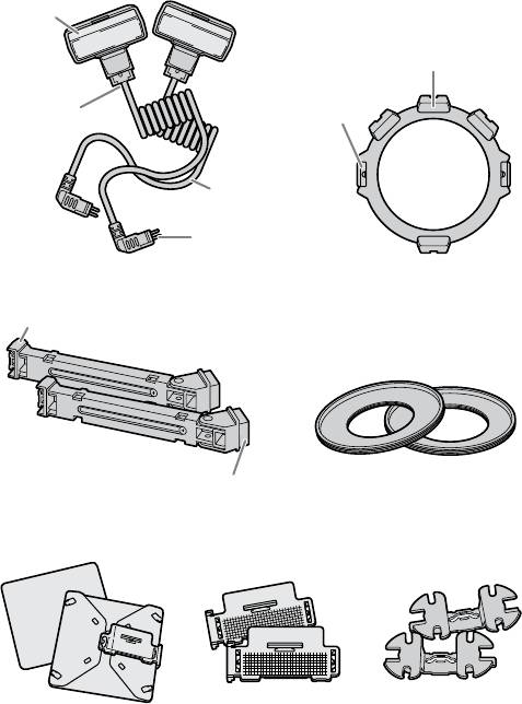
Macro Twin Flash
Twin Flash Unit*
Flashtube
Holder (14)
Shoe
Release
Attachment
tabs
Connecting
cord
Plug
Arm* (17)
Shoe
Adaptor ring (14)
ø49mm, ø55mm
Base
Diffuser* (44) Wide panel* (42) Cord reel* (18)
* Two supplied
9
HVL-MT24AM_GB 2-889-493-01 (1)
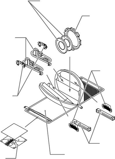
Example of storage
Adaptor ring ø49mm/ø55mm
Holder
Twin flash unit
Wide panel
Cord reel
Arm
Case
Diffuser
10
HVL-MT24AM_GB 2-889-493-01 (1)
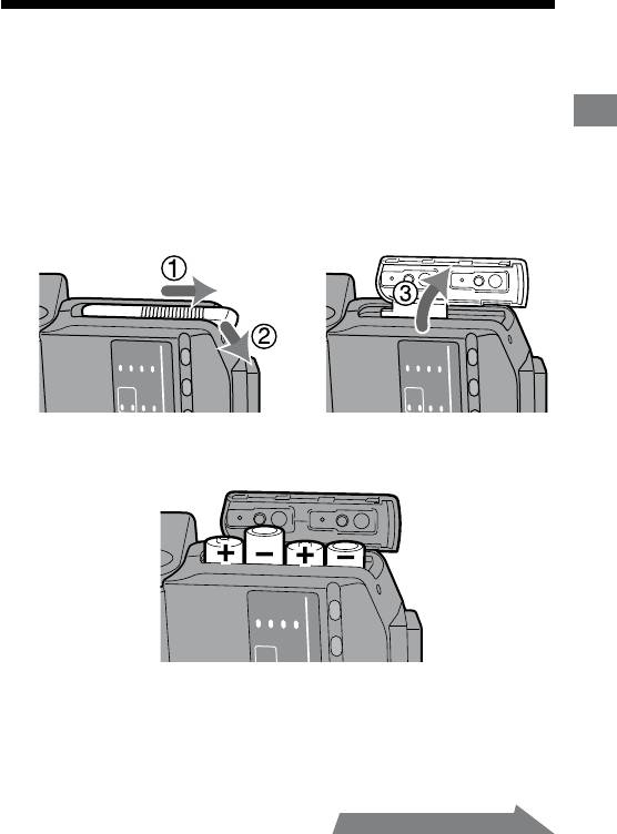
Inserting batteries
e HVL-MT24AM may be powered by :
* Batteries are not supplied.
Four AA-size alkaline batteries
Preparations
Four AA-size lithium batteries
Four AA-size rechargeable nickel-metal hydride (Ni-MH) batteries
Always ensure that rechargeable nickel-metal hydride batteries are charged in
the specied charger unit.
1 Open the battery-chamber door as shown.
2 Insert the batteries in the battery chamber as in the
diagram.
3 Close the battery-chamber door.
Follow the reverse steps when opening the battery-chamber door.
e lamp on the control panel comes on. If it does not come on, press the ash
ON/OFF button.
11
HVL-MT24AM_GB 2-889-493-01 (1)
Continued on the next page
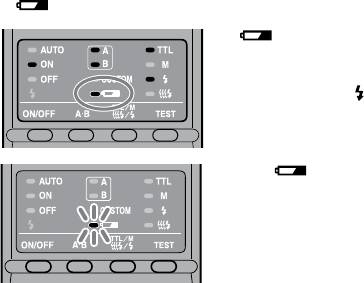
Checking Batteries
e lamp on the control panel comes on or blinks when the batteries are low.
lamp on
Changing the batteries is
recommended. e ash can still be
used in this state if (Flash-ready
lamp) on the rear of the unit is lit.
Only lamp blinking
Flash cannot be used.
Insert new batteries.
If nothing comes on when the ash ON/OFF button of the macro ash
controller is pressed, check the orientation of the batteries.
12
HVL-MT24AM_GB 2-889-493-01 (1)
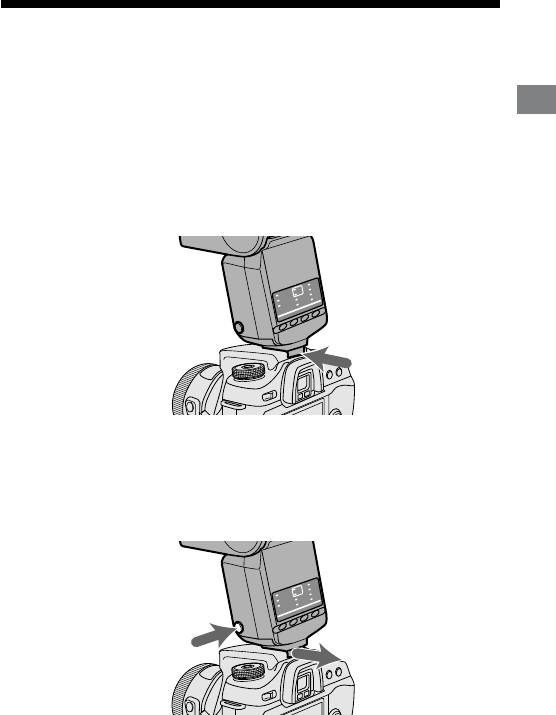
Attachment and removal of the macro
flash controller
Attaching the macro flash controller to the
Preparations
camera
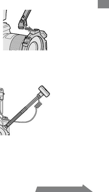
Push the mounting foot firmly onto the camera until it stops.
e macro ash controller is locked in place automatically.
If the built-in ash in the camera is protruding, lower it before attaching the
macro ash controller.
Removing the macro flash controller from the
camera
While pressing the mounting foot release button , remove
the macro flash controller .
13
HVL-MT24AM_GB 2-889-493-01 (1)
1
2
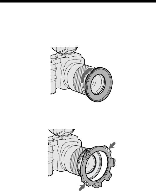
Attaching the macro twin flash
1 Screw the appropriate adaptor ring clockwise onto the
lens.
49mm and 55mm diameter adaptors are supplied.
2 While pressing the tabs on each side of the holder, place
the holder over the adaptor, and then release both tabs.
14
HVL-MT24AM_GB 2-889-493-01 (1)
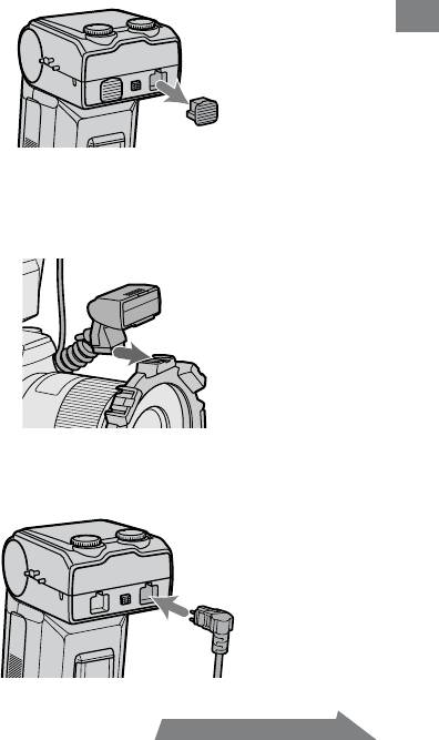
3 Remove the protective socket caps of the macro flash
controller.
For safe-keeping, place the caps in the case.
Replace caps aer use.
Preparations
4 Place the twin flash unit into the shoe of one of the
holders.
Use of an arm is also possible (p. 17).
5 Insert the plug of the twin flash unit into the twin-flash-
cord socket on the macro flash controller.
15
HVL-MT24AM_GB 2-889-493-01 (1)
Continued on the next page
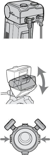
When removing the plug, press the twin flash-cord release
button on the macro flash controller and pull the plug
straight out of the socket.
Do not remove the plug by pulling on the connecting cord.
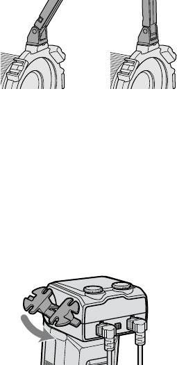
6 Adjust positions of the flashtubes as desired.
Each ashtube of the twin ash unit can be attached to any of the holder’s
four shoes.
Each ashtube of the twin ash unit can be tilted.
e holder can be rotated. Press the release tabs when removing or rotating
the holder.
16
HVL-MT24AM_GB 2-889-493-01 (1)
Attaching the arm
You can use an arm to position the ash unit away from the lens.
1 Attach the arm by sliding its base into one of the four
shoes on the holder.
Preparations
2 Attach the flashtube of the twin flash unit to the shoe of
the arm.
3 Set the arm at either of two lengths.
17
HVL-MT24AM_GB 2-889-493-01 (1)
Continued on the next page
4 When changing the angle to 60° position, hold both ends
of the arm and move it so that it clicks twice into place.
e angle of the arm can be adjusted to either of two positions, 60° or 90°
position.
Although the arm can be moved past the 60° and 90° positions to prevent
breakage, only use in these two positions. Also, do not attach the two arms
in combination. Doing so may damage the arms.
60° position 90° position
Using the cord reel
e cord reel can be attached to the side of the macro ash controller to take up
slack in the connecting cord of the twin ash unit.
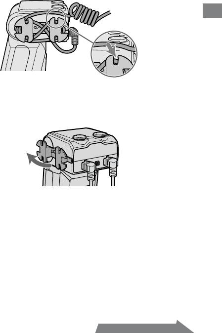
Attaching the cord reel to the macro flash
controller
As illustrated, first check the up-down direction of the cord
reel, and then attach the top of the cord reel followed by the
bottom of the cord reel to the reel-attachment points on the
side of the macro flash controller.
18
HVL-MT24AM_GB 2-889-493-01 (1)
Example of taking up the connecting cord
Secure the connecting cord slack by wrapping it around the reel and using the
outer notches, as illustrated.
Preparations
Removing the cord reel
Pull the bottom of the cord reel away from the macro flash
controller to remove it.
19
HVL-MT24AM_GB 2-889-493-01 (1)
Continued on the next page
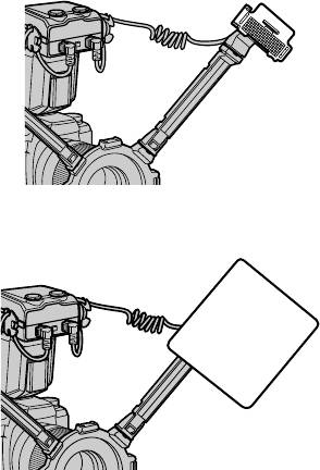
By attaching the wide panel to the ashtube, the ash coverage angle can be
increased (p. 42).
By using the diuser attached to the ashtube, strong shadows can be soened.
Always use the diuser with an arm (p. 44).
Make sure the ashtube is pointing at the subject. Do not allow the cord to get
in front of the ashtube or lens.
See page 51 for photographic examples.
If an arm is used when taking extreme close-ups with a 50mm F2.8 Macro lens,
the subject may not receive sucient lighting (p. 53).
20
HVL-MT24AM_GB 2-889-493-01 (1)
