Sony STR-SE501: Digital Component Hookups
Digital Component Hookups: Sony STR-SE501
Table of contents
- WARNING Precautions
- About This Manual T ABLE OF CONTENTS Additional Information
- Hooking Up the Components Unpacking
- Antenna Hookups
- Audio Component Hookups
- Video Component Hookups
- Digital Component Hookups
- 5.1CH Input Hookups
- Other Hookups
- CONTROL A1 hookup (STR-DE545 and STR-SE501 only) AUX AUDIO IN hookup Connecting the AC power cord
- Hooking Up and Setting Up the Speaker System
- Speaker System Hookup
- Speaker System Hookup
- Performing Initial Setup Operations
- Multi Channel Surround Setup
- Center speaker size ( Rear speaker size (
- Multi Channel Surround Setup
- Adjusting the speaker volume
- Before turning on the receiver Checking the connections Before You Use Your Receiver Multi Channel Surround Setup
- There is no sound no matter which component is selected. No sound is heard from one of the front speakers.
- Front Panel Parts Descriptions Location of Parts and Basic Operations ? 1 switch Function buttons
- INPUT MODE button
- Front Panel Parts Description
- 25
- Front Panel Parts Description
- Enjoying Surround Sound
- Selecting a Sound Field
- Sound field information
- Use the buttons on the front panel to operate the following modes Selecting a Sound Field
- Understanding the Multi-Channel Surround Displays
- Understanding the Multi-Channel Surround Displays
- Customizing Sound Fields
- Adjusting the level parameters Customizing Sound Fields
- Adjusting the bass/treble Resetting customized sound fields to the factory settings
- Customizing Sound Fields Adjustable parameters for each sound field
- Receiving Broadcasts
- Brief descriptions of buttons used to receive broadcasts
- Storing FM Stations Automatically Direct Tuning
- Preset Tuning Presetting radio stations Automatic Tuning
- Tuning to preset stations Receiving RDS broadcasts Displaying the RDS Information Using the Radio Data System (RDS)
- Using the Radio Data System (RDS) Monitoring traffic, news, or information programmes (EON) Locating a station by programme type
- Description of program types
- Other Operations
- Recording Naming Preset Stations and Program Sources
- Recording on a video tape Using the Sleep Timer Recording
- Adjustment Using the SET UP Button
- Troubleshooting Additional Information
- Reference sections for clearing the receiver’s memory
- Specifications Amplifier section
- FM tuner section AM tuner section Video section General
- Glossary
- Settings Using SUR, LEVEL, BASS/TREBLE, and SET UP buttons
- Remote Button Description (STR-DE445 only)
- Changing the factory setting of a function button
- Remote Button Description (STR-DE445 only)
- Index
8
GB
Hooking Up the Components
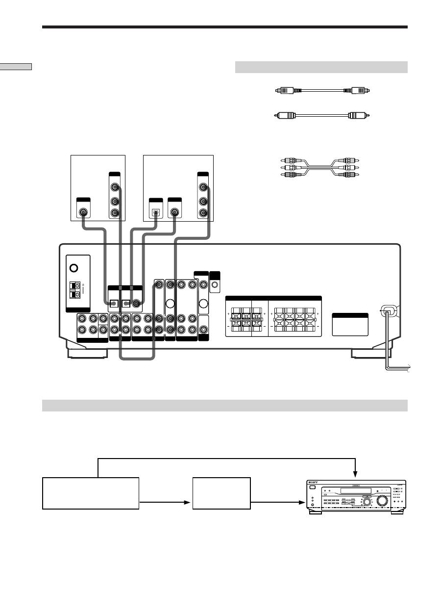
DVD player (etc.)*
Required cords
Optical digital cords (not supplied)
Coaxial digital cord (not supplied)
Audio/video cords (not supplied)
When connecting a cord, be sure to match the color-coded pins to
the appropriate jacks on the components.
Connect the digital output jacks of your DVD player and
satellite tuner (etc.) to the receiver’s digital input jacks to
bring the multi channel surround sound of a movie
theater into your home. To enjoy full effect of multi
channel surround sound, five speakers (two front
speakers, two rear speakers, and a center speaker) and a
sub woofer are required. You can also connect an LD
player with an RF OUT jack via an RF demodulator, such
as the Sony MOD-RF1 (not supplied).
Digital Component Hookups
Please note that you cannot connect an LD player’s AC-3 RF OUT jack directly to the receiver’s digital input jacks. You
must first convert the RF signal to either an optical or coaxial digital signal. Connect the LD player to the RF demodulator,
then connect the RF demodulator’s optical or coaxial digital output to the receiver’s OPTICAL or COAXIAL DVD/LD IN
jack. Refer to the instruction manual supplied with your RF Demodulator for details on AC-3 RF hookups.
Example of LD player connected via an RF demodulator
RF demodulator
LD player
Black
Black
Yellow
Yellow
Yellow (video)
Yellow (video)
White (L/audio)
White (L/audio)
Red (R/audio)
Red (R/audio)
Note
When making connections as shown above, be sure to set INPUT MODE (
3
on page 23) manually. The receiver may not operate correctly
if INPUT MODE is set to “AUTO.”
* When making digital audio connections to a DVD player, connect to either the coaxial OR optical digital jacks, and not
both. It is recommended to make digital audio connections to the coaxial jack.
** STR-DE545 and STR-SE501 only.
Note
The optical and coaxial digital input jacks on the receiver are
compatible with sampling frequencies of 32 kHz, 44.1 kHz, and
48 kHz.
DIGITAL
COAXIAL
OUTPUT
VIDEO
OUT
R
AUDIO
OUT
OUTPUT
L
DIGITAL
OPTICAL
OUTPUT
VIDEO
OUT
AUDIO
OUT
OUTPUT
DIGITAL
OPTICAL
OUTPUT
FRONT
REAR
SUB
WOOFER
AUDIO IN
AUDIO IN
TV/SAT
**
**
OPTICAL
OPTICAL
COAXIAL
DVD/LD
REC OUT
IN
AUDIO IN
VIDEO IN
AUDIO IN
VIDEO IN
AUDIO OUT
AUDIO IN
VIDEO OUT
VIDEO IN
VIDEO OUT
S-VIDEO
OUT
S-VIDEO
IN
AUDIO
OUT
4
Ω
8
Ω
CENTER
L
R
L
R
L
R
L
R
L
R
FRONT
REAR
R
L
R
L
R
L
R
SWITCHED 120W/1A MAX
SWITCHED 120W/1A MAX
AC 120V 60Hz
AC 120V 60Hz
L
R
L
R
L
CENTER
B FRONT A
FM
75
Ω
COAXIAL
AM
MD/TAPE
ANTENNA
DIGITAL IN
TV/SAT
5.1 CH INPUT
AUX
CD
DVD/LD
VIDEO
SUB
WOOFER
IMPEDANCE
SELECTOR
SPEAKERS
CTRL
A1
I I
MONITOR
AC OUTLET
TV or Satellite
tuner
DVD/LD
VIDEO IN
DIGITAL
DVD/LD IN
(COAXIAL)
(OPTICAL)
AC-3 RF
OUT
VIDEO OUT
MULTI CHANNEL DECODING
MASTER VOLUME
DISPLAY
INPUT MODE
VIDEO
MD/TAPE
CD
TUNER
AUX
DVD/LD
TV/SAT 5.1CH INPUT
CINEMA STUDIO
LEVEL
I
–
i
+
SET UP
BASS BOOST
TONE
FM/AM
MUTING
TONE
BASS
BOOST
MEMORY
FM MODE
RDS EON RDS PTY
PRESET/
– PTY SELECT +
– TUNING +
NAME
ENTER
SUR
BASS/
TREBLE
SOUND FIELD
A. F. D.
A
B
C
2CH
MODE
DIMMER
SPEAKERS
R
ON
r
OFF
A
PHONES
B
?
/
1
SHIFT
DIGITAL
DVD/LD IN
(COAXIAL)
or (OPTICAL)


