Yamaha KMA-500: NAMES OF PARTS AND THEIR FUNCTIONS
NAMES OF PARTS AND THEIR FUNCTIONS: Yamaha KMA-500
PREPARATION
NAMES OF PARTS AND THEIR FUNCTIONS
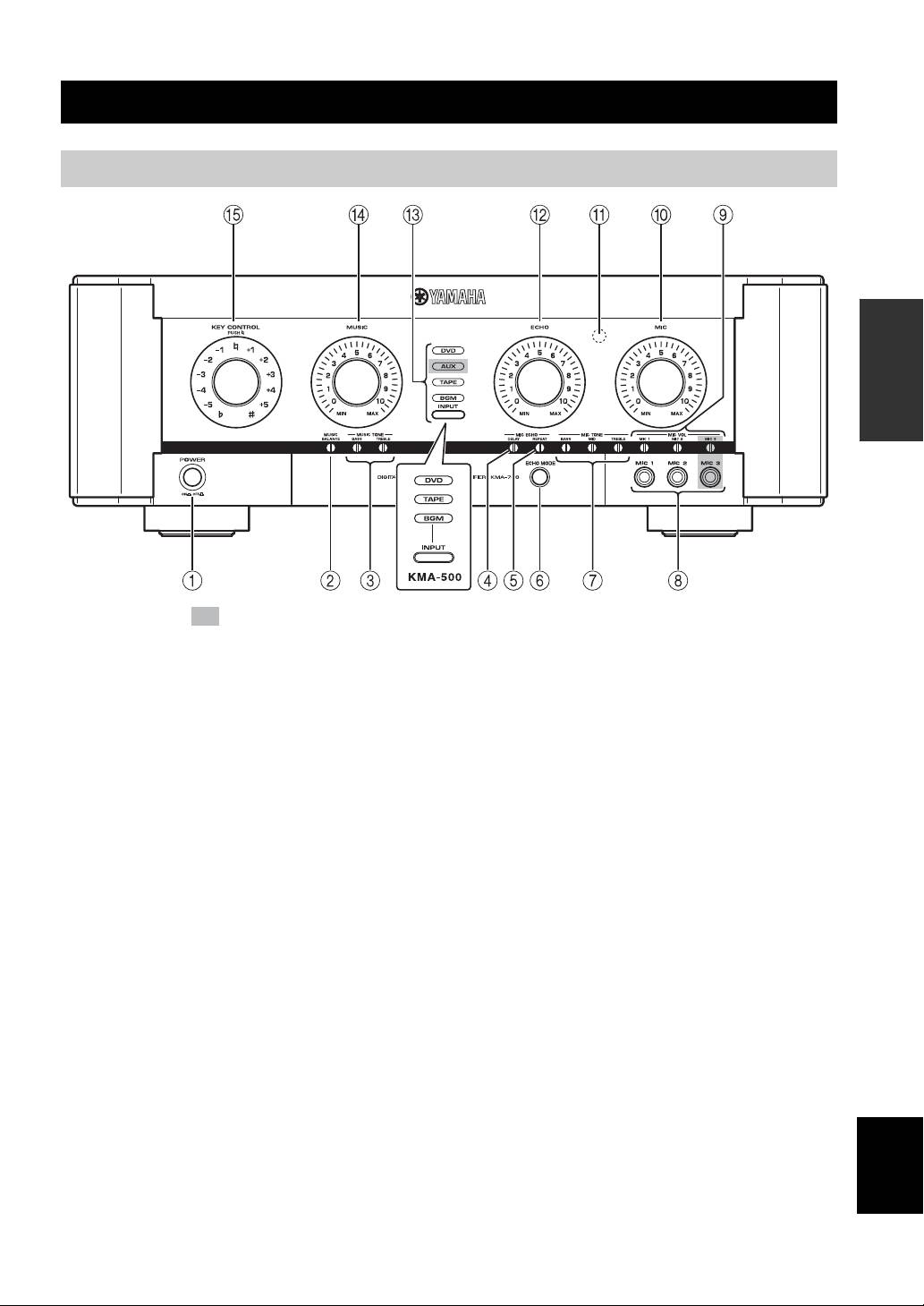
Front panel
PREPARATION
The shaded part ( ) is provided for KMA-700 only.
1 POWER (ON/OFF)
0 MIC
Turn the power ON/OFF.
Adjust the overall volume of all microphones.
2 MUSIC BALANCE
A Remote sensor
Adjust the volume balance.*
This sensor receives signals from the remote control.
3 MUSIC TONE (BASS/TREBLE)
B ECHO
Adjust the low/high frequency response.*
Adjust the amount of echo.
4 MIC ECHO DELAY
C INPUT/Input source indicators (DVD/AUX**/
Adjust the delay time between echoes.*
TAPE/BGM)
INPUT is not available in the default setting.
5 MIC ECHO REPEAT
To activate INPUT, refer to “Input mode” on page 14.
Adjust the amount of feedback.*
Input source indicators indicate the input source currently
6 ECHO MODE
active.
Select NORMAL, WIDE (stereo) or SPACIOUS** echo.
D MUSIC
SPACIOUS echo is an effect that produces both
Adjust the volume of the music source.
NORMAL and WIDE echo with a time lag. The LED
lights up in amber/green** when WIDE/SPACIOUS**
E KEY CONTROL
echo is selected.
To transpose the key of the played music, rotate this
control. The key can be changed in halftone steps in 5
7 MIC TONE (BASS/MID/TREBLE)
steps; either higher or lower. To reset the key to the
Adjust the low/middle/high frequency response of
natural key, press this control. If over 4 seconds of silence
microphones.*
occurs, the unit assumes the played song has finished and
English
8 MIC jacks (1/2/3**)
resets the key to natural.
Connect microphones to these jacks.
* Use a flathead screwdriver to adjust.
9 MIC VOL (1/2/3**)
** KMA-700 only
Adjust the microphone input level.*
3 En
NAMES OF PARTS AND THEIR FUNCTIONS
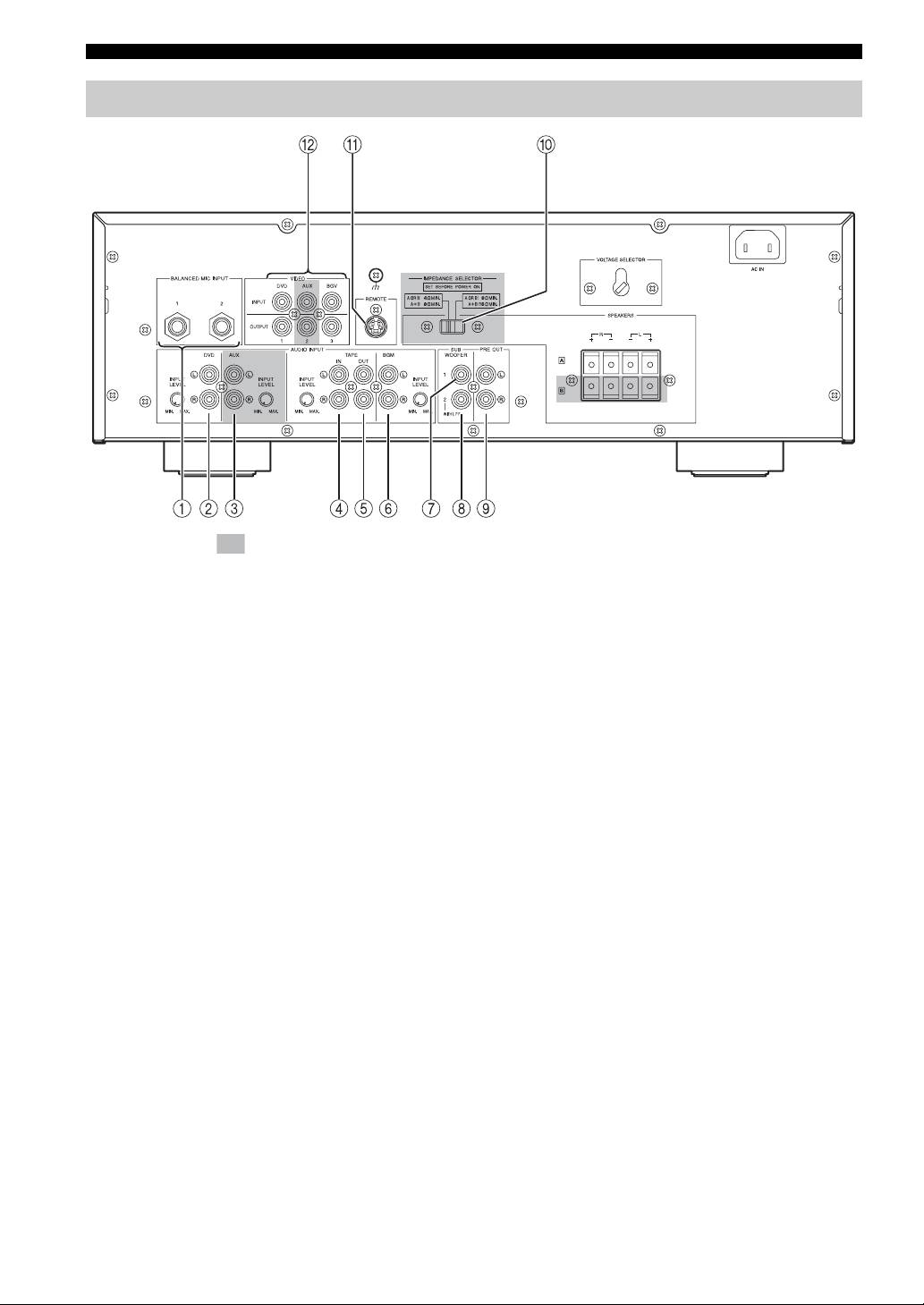
Rear panel
(Asia model)
The shaded part ( ) is provided for KMA-700 only.
For details on component connection, refer to “SYSTEM
9 PRE OUT jacks
CONNECTIONS” on page 6.
Connect to the input jacks of the extension power
amplifier.
1 BALANCED MIC INPUT jacks (1/2)
Connect microphones to these jacks.
0 IMPEDANCE SELECTOR*
These are balanced inputs and each connects to the same
Refer to “IMPEDANCE SELECTOR” on page 7.
circuit MIC 1 and 2 on the front panel.
A REMOTE jack
2 DVD audio input jacks
Connect to an external remote control.
Connect to the output jacks of KARAOKE equipment or
Refer to “Connecting an external remote control” on page
DVD player.
8.
3 AUX audio input jacks*
B VIDEO INPUT jacks
Connect to the output jacks of a TAPE player, VCR, etc.
Connect to the input jack of the video output of a DVD,
AUX*, or background video player or video camera, etc.
4 TAPE audio input jacks
Connect to the output jacks of a TAPE player, VCR, etc.
5 TAPE audio output jacks
Connect to the input jacks of a TAPE player, VCR, etc.
* KMA-700 only
6 BGM audio input jacks
Connect to the output jacks of the source component of
background music.
7 SUBWOOFER jack without low-pass filter
Connect to the input jack of the subwoofer with a low-
pass filter. This jack outputs the monaural signal directly.
8 SUBWOOFER jack with low-pass filter
Connect to the input jack of the subwoofer.
4 En
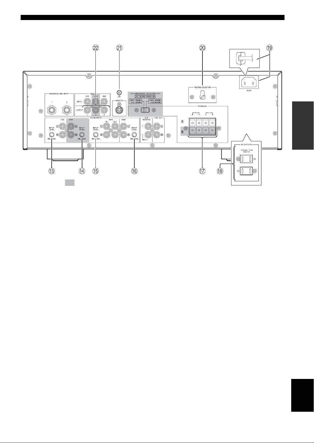
NAMES OF PARTS AND THEIR FUNCTIONS
(Asia model)
PREPARATION
The shaded part ( ) is provided for KMA-700 only.
C DVD INPUT LEVEL
K Signal ground terminal
Adjust the balance of the DVD input level with respect to
Connect this terminal if a humming noise is emitted when
other inputs (AUX*, TAPE, BGM).
connecting this amplifier.
D AUX INPUT LEVEL*
L VIDEO OUTPUT jacks
Adjust the balance of the AUX input level with respect to
Connect to the video input of the monitor.
other inputs (DVD, TAPE, BGM).
E TAPE INPUT LEVEL
Adjust the balance of the TAPE input level with respect to
other inputs (DVD, AUX*, BGM).
* KMA-700 only
F BGM INPUT LEVEL
Adjust the balance of the BGM input level with respect to
other inputs (DVD, AUX*, TAPE).
G SPEAKERS (Speaker system terminal(s))
Connect to the speaker system(s).
For KMA-500, only one speaker system is available.
H AC OUTLETS (Max. total power consumption:
100 W. U.S.A. model only)
Refer to “AC OUTLETS” on page 9.
I AC IN (Except U.S.A. model)
Refer to “AC IN” on page 9.
Power cable (U.S.A. model only)
Plug this cable into an AC wall outlet.
English
J VOLTAGE SELECTOR (Except U.S.A. model)
Refer to “VOLTAGE SELECTOR” on page 9.
5 En
Оглавление
- Caution: Read this before operating your unit
- CONTENTS
- HANDLING PRECAUTIONS
- NAMES OF PARTS AND THEIR FUNCTIONS
- SYSTEM CONNECTIONS
- CONNECTIONS
- CONFIGURATION DIAGRAM
- REMOTE CONTROL
- GENERAL OPERATION
- SETUP MODE
- TROUBLESHOOTING
- AFTER-SALES SERVICING
- SPECIFICATIONS
- 警告:操作本机前请认真阅读
- 目录
- 使用注意事项
- 部件名称及其功能
- 系统连接
- 连接
- 配置图
- 遥控器
- 一般操作
- 设定模式
- 故障排除
- 售后服务
- 技术规格
- Precaución: lea las indicaciones siguientes antes de utilizar este aparato
- ÍNDICE
- PRECAUCIONES DE MANIPULACIÓN
- NOMBRES Y FUNCIONES DE LAS PIEZAS
- CONEXIONES DEL SISTEMA
- CONEXIONES
- DIAGRAMA DE CONFIGURACIÓN
- MANDO A DISTANCIA
- FUNCIONAMIENTO GENERAL
- MODO DE CONFIGURACIÓN
- SOLUCIÓN DE PROBLEMAS
- SERVICIO POSVENTA
- ESPECIFICACIONES
- Предупреждение: Внимательно изучите это перед использованием аппарата
- СОДЕРЖАНИЕ
- МЕРЫ ПРЕДОСТОРОЖНОСТИ ПРИ ОБРАЩЕНИИ
- НАЗВАНИЯ ДЕТАЛЕЙ И ИХ ФУНКЦИИ
- СОЕДИНЕНИЯ СИСТЕМЫ
- СОЕДИНЕНИЯ
- СХЕМА КОНФИГУРАЦИИ
- ПУЛЬТ ДУ
- ОБЩЕЕ УПРАВЛЕНИЕ
- РЕЖИМ НАСТРОЙКИ
- ВОЗМОЖНЫЕ НЕИСПРАВНОСТИ И СПОСОБЫ ИХ УСТРАНЕНИЯ
- ПОСЛЕПРОДАЖНОЕ ОБСЛУЖИВАНИЕ
- ТЕХНИЧЕСКИЕ ХАРАКТЕРИСТИКИ
