Yamaha KMA-500: CONNECTIONS
CONNECTIONS: Yamaha KMA-500
CONNECTIONS
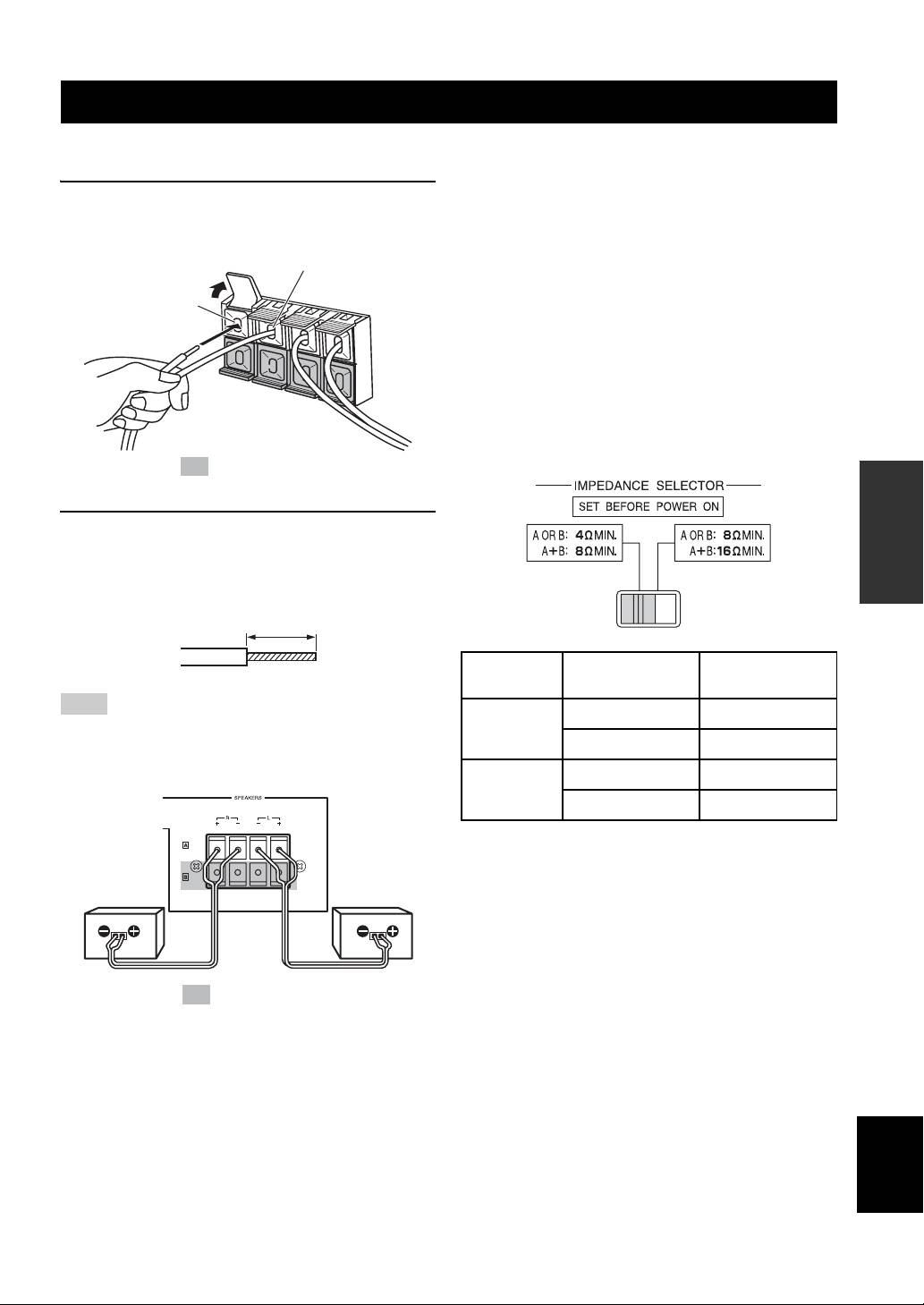
■ Connecting speaker cords
■ Important precautions for speaker
connection
1 Pull the lever up to open, then insert the
• The maximum outputs of this unit are as follows:
KMA-700..................................................120 W + 120 W
conductor wire into the hole.
KMA-500..................................................100 W + 100 W
(–) cord to (–) terminal
Accordingly, the maximum input power of the speakers
used must exceed the above.
(+) cord to
• Use Yamaha speakers to prevent any trouble or
(+) terminal
damage caused by mismatching.
[For KMA-700]
IMPEDANCE SELECTOR
• Before turning on this unit, be sure to set
IMPEDANCE SELECTOR on the rear panel to the
position whose requirements your speaker system
meets.
The shaded part ( ) is provided for KMA-700 only.
OPERATION
2 Close the lever to secure the conductor wire.
Before connection, strip a section of coating 15 mm
(9/16”) in length from the end of each cord using a
tool such as pliers.
(Low) (High)
15 mm (9/16”)
Switch
If your system
Speaker
position
uses:
impedance level
Note
One speaker system
4
Ω or higher
Be careful that the cord conductors projected from a terminal do
Low
Two speaker systems
8
Ω or higher
not contact with another cord. Contact from the conductors of
different speaker cords may cause damage to the system.
One speaker system
8
Ω or higher
High
Two speaker systems
16
Ω or higher
• Do not change IMPEDANCE SELECTOR setting
while the power to this unit is on, otherwise this unit
Right
Left
may be damaged.
speaker
speaker
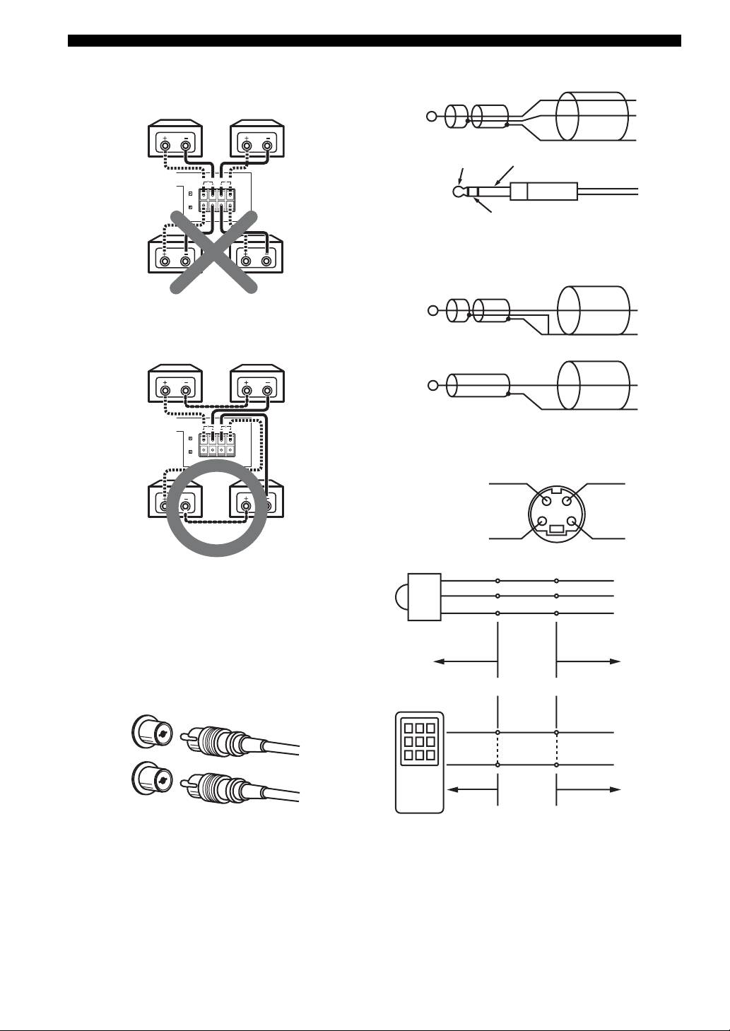
Connection examples
The minimum speaker impedance is 4 Ω. If two 6 Ω
speaker systems are connected in parallel, this will exceed
the design value and trigger a safety protector device.
When two speaker systems are used and the protector is
The shaded part ( ) is provided for KMA-700 only.
frequently activated, the speaker systems should be
connected serially instead.
English
7 En
CONNECTIONS
1. Parallel connection
■ Connecting to the balanced input
(each speaker should be 8 Ω or more)
HOT
6 Ω 6 Ω
COLD
GND
HOT
GND
6 Ω + 6 Ω ➝ 3 Ω
(<4 Ω : NG)
COLD
■ Connecting to the unbalanced input
2. Series connection
HOT
(total: over 4 Ω is available)
GND
or
6 Ω 6 Ω
HOT
GND
6 Ω + 6 Ω = 12 Ω
(>4 Ω : OK)
■ Connecting an external remote control
REMOTE
GND
(Direct)
REMOTE
+5V_OUT
[For KMA-500]
+5V
+5V_OUT
The speaker impedance must be between 8 Ω to 16 Ω.
OUT
REMOTE
GND
GND
External remote control
■ Connecting the RCA pin plugs
satellite
When connecting RCA pin plugs, be sure to insert the red
plug into the red jack and the white plug into the white
RMC KMA-700/
jack.
KMA-500
White
REMOTE (Direct)
Left
White
GND
Right
Red
RMC KMA-700/
Red
KMA-500
8 En
CONNECTIONS
1. External remote control satellite
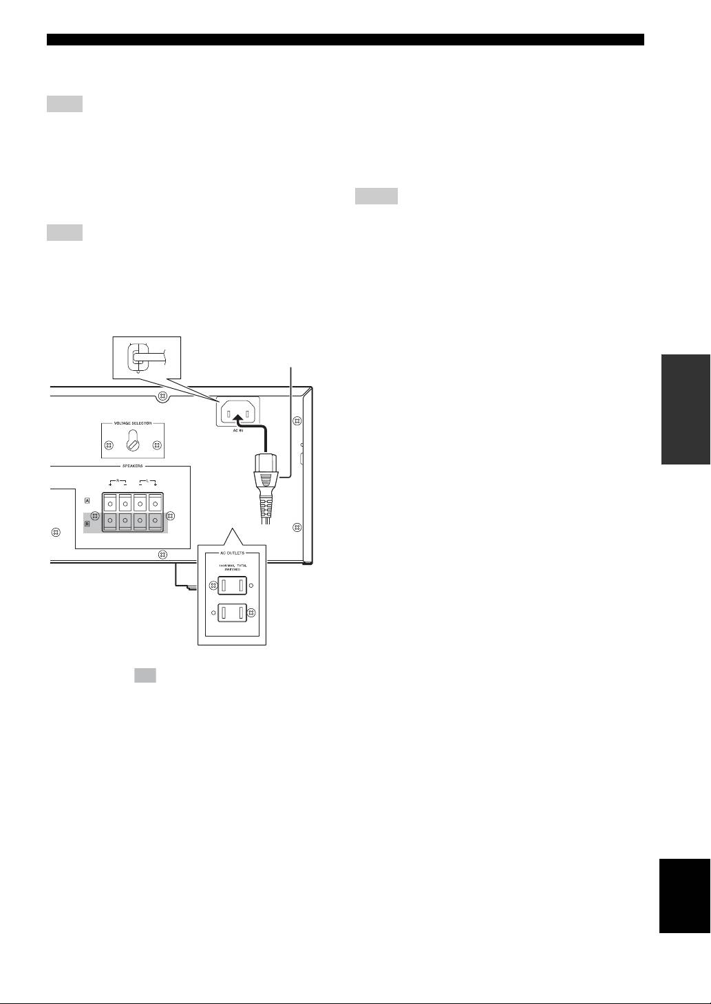
AC OUTLETS
Connect to +5V_OUT, REMOTE and GND.
(SWITCHED. U.S.A. model only)
Use these outlets to connect the power cables from your
Note
other components to this unit. The power to AC
By connecting the remote control satellite to this input, this unit
OUTLETS is controlled by POWER on the front panel of
can receive the signal of the remote control.
this unit. The outlets supply power to any connected
component whenever the power of this unit is turned on.
2. REMOTE (Direct)
Total power consumption is 100 W.
Connect to REMOTE (Direct) and GND.
Connect to the infrared diode output (open collector) of
Notes
RMC.
• Be careful that the total power consumption does not exceed the
Note
wattage marked on the rear panel. Do not connect appliances
other than system components to the power outlets of this unit.
By connecting the REMOTE (Direct) to this input, this unit can
• Do not connect a TV set to this unit; even if it indicates a power
receive the signal of the REMOTE.
consumption value below the permissible value when the TV
power is turned on.
■ Power related switch and connections
on the rear panel
Supplied power cable
(Except U.S.A. model)
OPERATION
(Asia model)
The shaded part ( ) is provided for KMA-700 only.
The parts in the sub illustrations are provided for U.S.A.
model only.
AC IN
(Except U.S.A. model)
Connect the supplied power cable to AC IN.
Power cable
Plug the power cable into the AC wall outlet after all other
connections are complete.
VOLTAGE SELECTOR
(Except U.S.A. model)
English
VOLTAGE SELECTOR on the rear panel of this unit
must be set for your local main voltage BEFORE plugging
the power cable into the AC wall outlet.
9 En
Оглавление
- Caution: Read this before operating your unit
- CONTENTS
- HANDLING PRECAUTIONS
- NAMES OF PARTS AND THEIR FUNCTIONS
- SYSTEM CONNECTIONS
- CONNECTIONS
- CONFIGURATION DIAGRAM
- REMOTE CONTROL
- GENERAL OPERATION
- SETUP MODE
- TROUBLESHOOTING
- AFTER-SALES SERVICING
- SPECIFICATIONS
- 警告:操作本机前请认真阅读
- 目录
- 使用注意事项
- 部件名称及其功能
- 系统连接
- 连接
- 配置图
- 遥控器
- 一般操作
- 设定模式
- 故障排除
- 售后服务
- 技术规格
- Precaución: lea las indicaciones siguientes antes de utilizar este aparato
- ÍNDICE
- PRECAUCIONES DE MANIPULACIÓN
- NOMBRES Y FUNCIONES DE LAS PIEZAS
- CONEXIONES DEL SISTEMA
- CONEXIONES
- DIAGRAMA DE CONFIGURACIÓN
- MANDO A DISTANCIA
- FUNCIONAMIENTO GENERAL
- MODO DE CONFIGURACIÓN
- SOLUCIÓN DE PROBLEMAS
- SERVICIO POSVENTA
- ESPECIFICACIONES
- Предупреждение: Внимательно изучите это перед использованием аппарата
- СОДЕРЖАНИЕ
- МЕРЫ ПРЕДОСТОРОЖНОСТИ ПРИ ОБРАЩЕНИИ
- НАЗВАНИЯ ДЕТАЛЕЙ И ИХ ФУНКЦИИ
- СОЕДИНЕНИЯ СИСТЕМЫ
- СОЕДИНЕНИЯ
- СХЕМА КОНФИГУРАЦИИ
- ПУЛЬТ ДУ
- ОБЩЕЕ УПРАВЛЕНИЕ
- РЕЖИМ НАСТРОЙКИ
- ВОЗМОЖНЫЕ НЕИСПРАВНОСТИ И СПОСОБЫ ИХ УСТРАНЕНИЯ
- ПОСЛЕПРОДАЖНОЕ ОБСЛУЖИВАНИЕ
- ТЕХНИЧЕСКИЕ ХАРАКТЕРИСТИКИ
