Yamaha AX-497: CONTROLS AND FUNCTIONS
CONTROLS AND FUNCTIONS: Yamaha AX-497
CONTROLS AND FUNCTIONS
3
INTR
ODUCTION
English
■
AX-497
■
AX-397
1
POWER
Press inward to the ON position to provide this unit with
power supply from the AC wall outlet. In this state, you
can turn on this unit or set it to the standby mode by
pressing STANDBY/ON.
When you turn on this unit, there will be a few second
delay before this unit can reproduce sound.
Press again to release it outward to the OFF position to
completely cut off power supply from the AC wall outlet.
2
STANDBY indicator
Lights up when this unit is in the standby mode.
3
STANDBY/ON
Turns on this unit or sets it to the standby mode.
• This switch is operational only when POWER is pressed inward
to the ON position.
• In the standby mode, this unit consumes a small amount of
power to receive infrared-signals from the remote control.
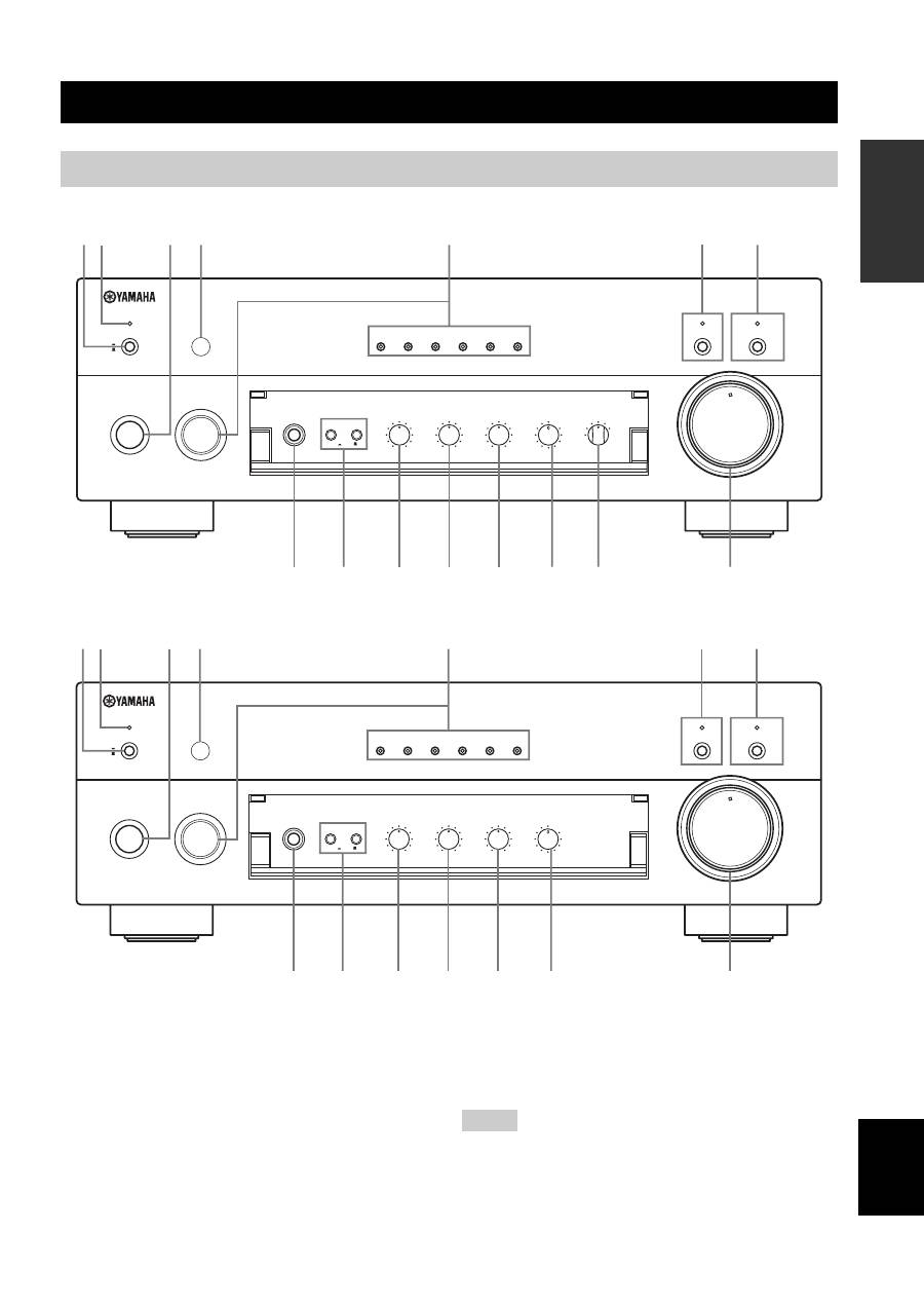
CONTROLS AND FUNCTIONS
Front panel
STANDBY
/ON
STANDBY
INPUT
PHONES
SPEAKERS
BASS
A
POWER
ON
OFF
ON
OFF
AUX
MD
TAPE
CD/DVD
TUNER
PHONO
PURE DIRECT
CD/DVD DIRECT AMP
B
5
1
4
2
3
5
1
4
2
3
+
–
TREBLE
5
1
4
2
3
5
1
4
2
3
+
–
BALANCE
5
1
4
2
3
5
1
4
2
3
TUNER
PHONO
TAPE
MD
AUX
R
L
LOUDNESS
REC OUT
VOLUME
7
–30dB
FLAT
CD/DVD
10
9
5
6
1
4
2
3
0
12
12
2
8
4
∞
20
20
60
60
26
26
40
40
16
16
-dB
-dB
8
DISPLAY
4
1
3
2
5
F
D
C
B
A
9
0
E
8
6
STANDBY
/ON
STANDBY
INPUT
PHONES
SPEAKERS
BASS
5
1
4
2
3
5
1
4
2
3
A
POWER
ON
OFF
ON
OFF
AUX
MD
TAPE
CD/DVD
TUNER
PHONO
TAPE MONITOR
CD/DVD DIRECT AMP
B
+
–
TREBLE
5
1
4
2
3
5
1
4
2
3
+
–
BALANCE
5
1
4
2
3
5
1
4
2
3
R
L
LOUDNESS
VOLUME
7
–30dB
FLAT
10
9
5
6
1
4
8
2
3
DISPLAY
4
1
3
2
5
D
C
B
A
9
0
8
7
0
12
12
2
8
4
∞
20
20
60
60
26
26
40
40
16
16
-dB
-dB
F
Notes

CONTROLS AND FUNCTIONS
4
4
Remote control sensor
Receives signals from the remote control.
5
INPUT selector and indicators
Selects the input source you want to listen to.
The input source indicators light up when the
corresponding input sources are selected.
6
PURE DIRECT and indicator
(AX-497 only)
Allows you to listen to a source in the purest possible
sound.
The indicator above it lights up when this function is
turned on.
See page 13 for details.
7
TAPE MONITOR and indicator
(AX-397 only)
Allows you to listen to the sound played back on the tape
deck connected to the TAPE terminals on the rear panel of
this unit.
When the tape deck is used for recording, you can also
monitor the sound being recorded.
The indicator above it lights up when this function is
turned on.
• When this function is on (the indicator lights up), TAPE (tape
deck) cannot be selected with the INPUT selector.
• To listen to the source selected with the INPUT selector, press
again to turn off the function (the indicator turns off as a result).
• When TAPE (tape deck) is selected with the INPUT selector,
this function will not turn on even if TAPE MONITOR is
pressed.
8
CD/DVD DIRECT AMP and indicator
Allows you to listen to a CD or a DVD source in the
purest sound.
The indicator above it lights up when this function is
turned on.
See page 13 for details.
9
PHONES jack
Outputs audio for private listening with headphones.
Press both SPEAKERS A and B switches on the front
panel to release them outward to the OFF position.
0
SPEAKERS A/B
Turns on or off the speaker set connected to the
SPEAKERS A and/or B terminals on the rear panel each
time the corresponding button is pressed.
A
BASS
Increases or decreases the low frequency response. The 0
position produces a flat response.
See page 13 for details.
B
TREBLE
Increases or decreases the high frequency response. The 0
position produces a flat response.
See page 13 for details.
C
BALANCE
Adjusts the sound output balance of the left and right
speakers to compensate for sound imbalances caused by
speaker locations or listening room conditions.
See page 13 for details.
D
LOUDNESS
Retains a full tonal range at any volume level to
compensates for the human ears’ loss of sensitivity to high
and low-frequency ranges at low volume.
See page 13 for details.
E
REC OUT selector
(AX-497 only)
Selects a source for recording to the MD recorder or the
tape deck independently of the INPUT selector setting,
allowing you to record the selected source while listening
to another source.
See page 14 for details.
F
VOLUME
Controls the sound output level.
This does not affect the OUT (REC) level.
■
Opening and closing the front panel
door
When you want to use the controls behind the front panel
door, open the door by gently pressing on the lower part of
the panel. Keep the door closed when not using these
controls to protect the controls from dust, etc.
Notes
CONTROLS AND FUNCTIONS
5
INTR
ODUCTION
English
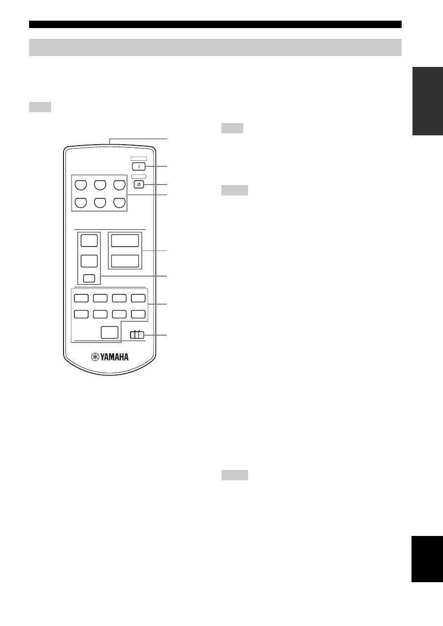
This section describes the function of each control on the
remote control used to control this unit or a YAMAHA
CD player, tuner, tape deck, etc. with the remote control
capability.
Some components may not be controlled by this remote control.
■
Controlling this unit
1
Infrared signal transmitter
Sends signals to this unit.
2
POWER
Turns on this unit.
This button is operational only when POWER on the front panel
is pressed inward to the ON position.
3
STANDBY
Sets this unit to the standby mode.
• This button is operational only when POWER on the front
panel is pressed inward to the ON position.
• In the standby mode, this unit consumes a small amount of
power in order to receive infrared-signals from the remote
control.
4
Input selector buttons
Select the input source you want to listen to.
5
VOLUME +/–
Controls the sound output level.
This does not affect the OUT (REC) level.
■
Controlling other components
The functions of the buttons to control other YAMAHA
components are the same as those of the corresponding
buttons on those components. Refer to those components’
instruction manuals for details.
6
Tuner buttons
Control various functions of the tuner.
PRESET +/–
Selects a preset station number (1 to 8).
A/B/C/D/E
Selects a preset station group (A to E).
7
CD player / tape deck buttons
Control various functions of the CD player or the tape
deck.
• DIR B and A/B apply only to the double cassette tape deck.
• Pressing DIR A will reverse the tape direction on the single
cassette tape deck with the automatic reverse function.
8
CD/TAPE selector switch
Switches to control either CD player functions or tape
deck functions.
Remote control
Note
CD/DVD
PHONO
TUNER
POWER
STANDBY
MD
TAPE
AUX
+
–
u
d
DISPLAY
A/B
REC
DISC
DIR A
p
DIR B
A/B/C/D/E
PRESET
VOLUME
TAPE
CD
w
e
f
b
s
a
DISPLAY
1
2
4
7
6
8
3
5
Note
Notes
Notes
CONTROLS AND FUNCTIONS
6
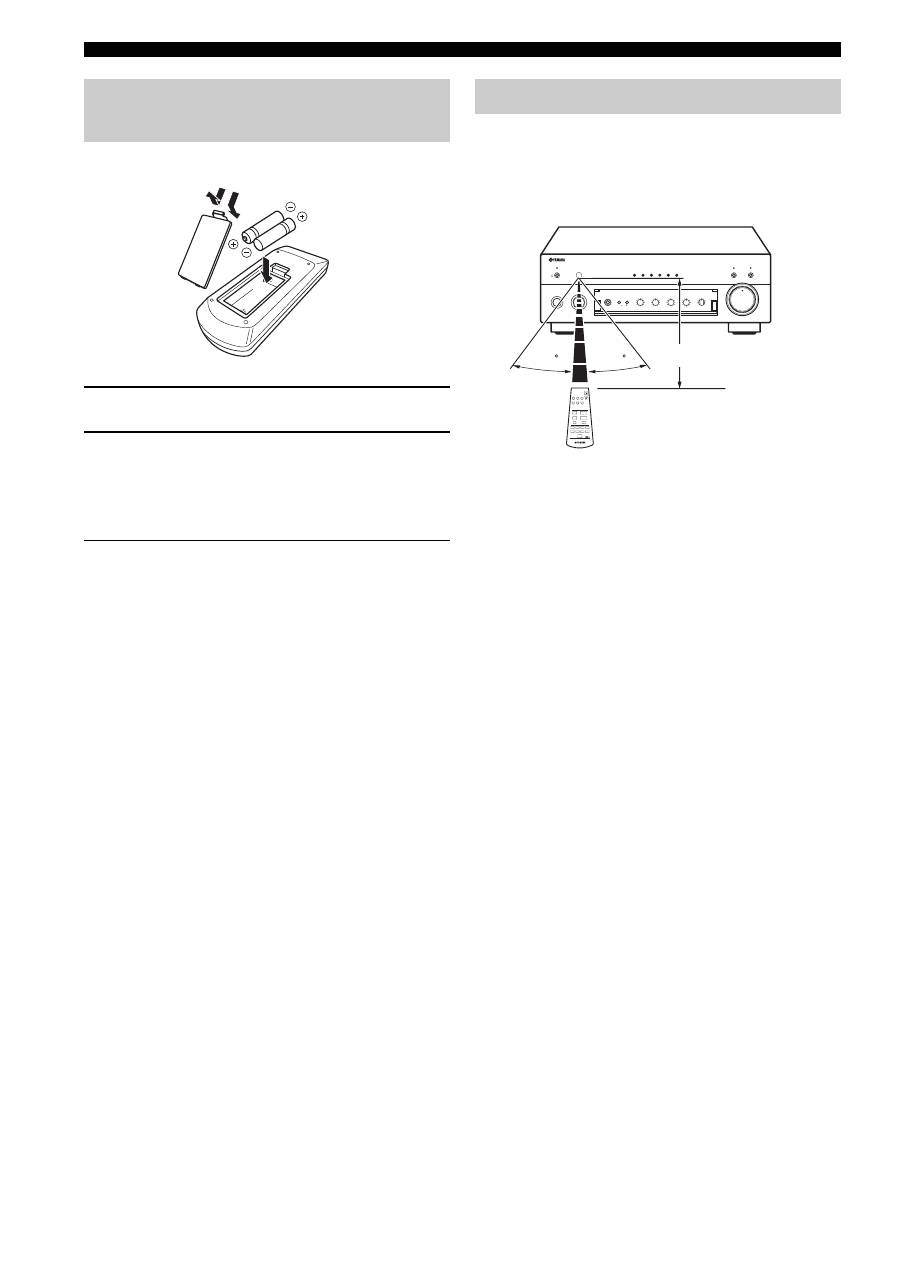
1
Open the battery compartment cover.
2
Insert two supplied batteries
(AAA, R03, UM-4) according to the polarity
markings (+ and –) on the inside of the
battery compartment.
3
Close the cover back.
■
Notes on batteries
• Change all of the batteries if you notice the following
conditions; the operation range of the remote control decreases,
the indicator does not flash or its light becomes dim.
• Use AAA, R03, UM-4 batteries.
• Make sure that the polarities are correct. See the illustration
inside the battery compartment.
• Remove the batteries if the remote control is not used for an
extended period of time.
• Do not use old batteries together with new ones.
• Do not use different types of batteries (such as alkaline and
manganese batteries) together. Read the packaging carefully as
these different types of batteries may have the same shape and
color.
• We strongly recommend using alkaline batteries.
• If the batteries have leaked, dispose of them immediately. Avoid
touching the leaked material or letting it come into contact with
clothing, etc. Clean the battery compartment thoroughly before
installing new batteries.
• Do not throw away batteries with general house waste; dispose
of them correctly in accordance with your local regulations.
The remote control transmits a directional infrared beam.
Be sure to aim the remote control directly at the remote
control sensor on the front panel of this unit during
operation.
■
Handling the remote control
• The area between the remote control and this unit must
be clear of large obstacles.
• Do not spill water or other liquids on the remote
control.
• Do not drop the remote control.
• Do not leave or store the remote control in the
following types of conditions:
– places of high humidity, such as near a bath
– places of high temperature, such as near a heater or
a stove
– places of extremely low temperatures
– dusty places
• Do not expose the remote control sensor to strong
lighting, in particular, an inverter type fluorescent
lamp; otherwise, the remote control may not work
properly. If necessary, position this unit away from
direct lighting.
Installing batteries in the remote control
1
3
2
Using the remote control
STANDBY
/ON
STANDBY
INPUT
PHONES
SPEAKERS
BASS
5
1
4
2
3
5
1
4
2
3
A
POWER
ON
OFF
ON
OFF
AUX
MD
TAPE
CD/DVD
TUNER
PHONO
PURE DIRECT
CD/DVD DIRECT AMP
B
+
–
TREBLE
5
1
4
2
3
5
1
4
2
3
+
–
BALANCE
5
1
4
2
3
5
1
4
2
3
TUNER
PHONO
TAPE
MD
AUX
R
L
LOUDNESS
REC OUT
VOLUME
7
–30dB
FLAT
CD/DVD
10
9
5
6
1
4
2
3
8
30
30
0
12
12
2
8
4
∞
20
20
60
60
26
26
40
40
16
16
-dB
-dB
CD/DVD
PHONO
TUNER
POWER
STANDBY
MD
TAPE
AUX
+
–
MUTE
A/B/C/D/E
VOLUME
TAPE
CD
u
d
PRESET
DISPLAY
A/B
REC
DISC
DIR A
p
DIR B
w
e
f
b
s
a
DISPLAY
Approximately 6 m
CONTROLS AND FUNCTIONS
7
INTR
ODUCTION
English
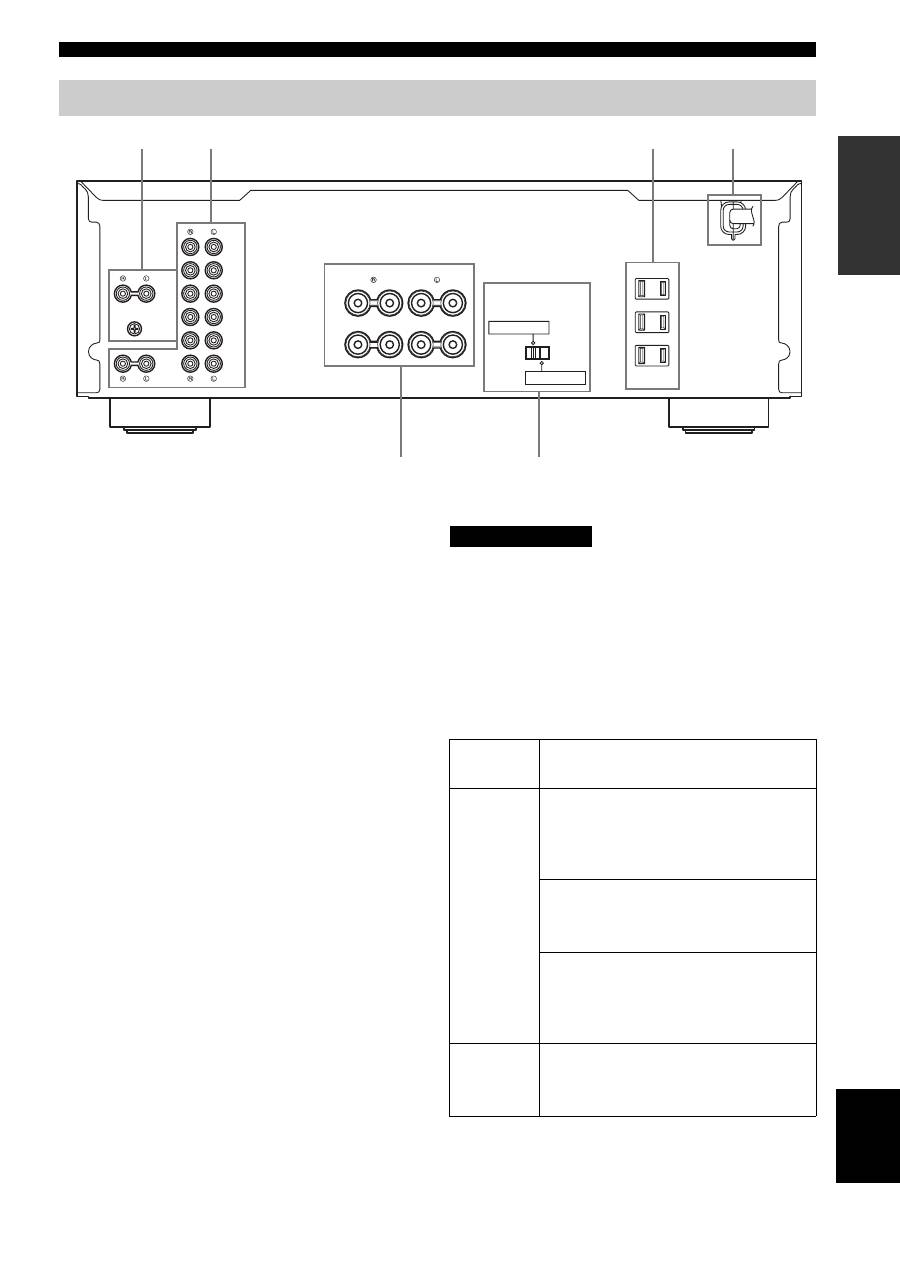
1
PHONO jacks and GND terminal
See page 8 for connection information.
2
Audio input/output jacks
See page 8 for connection information.
3
AC OUTLET(S)
Use to supply power to your other audio/video
components.
See page 10 for details.
4
AC power supply cord
See page 10 for connection information.
5
SPEAKERS terminals
Connect one or two speaker sets.
See page 8 for connection information.
6
IMPEDANCE SELECTOR
See “IMPEDANCE SELECTOR switch” on this page.
■
Asia and General models only
VOLTAGE SELECTOR is only applicable to the Asia and
General models.
VOLTAGE SELECTOR
See page 10 for details.
■
IMPEDANCE SELECTOR switch
Do not change the IMPEDANCE SELECTOR switch
while the power of this unit is turned on, as doing so may
damage the unit.
If this unit fails to turn on, the IMPEDANCE SELECTOR
switch may not be fully slid to either position. If this is the
case, slide the switch all the way to either position when
this unit’s power supply is completely cut off.
Select the switch position (left or right) according to the
impedance of the speakers in your system.
Rear panel
AC OUTLETS
IMPEDANCE SELECTOR
SPEAKERS
TUNER
TAPE
IN
(PLAY)
OUT
(REC)
MD
AUX
GND
PHONO
CD/DVD
IN
(PLAY)
OUT
(REC)
SWITCHED
100W MAX. TOTAL
+
+
A
B
–
–
A OR B: 4
Ω
MIN / SPEAKER
A+B: 8
Ω
MIN / SPEAKER
A OR B: 6
Ω
MIN / SPEAKER
5
1
2
3
4
6
(U.S.A. model)
Switch
position
Impedance level
Right
Asia model
• If you use one set (A or B), the impedance of
each speaker must be 8
Ω
or higher.
• If you use two sets (A and B), the impedance
of each speaker must be 16
Ω
or higher.
Canada model
• You can use one set (A or B), and the
impedance of each speaker must be 6
Ω
or
higher.
Other models
• If you use one set (A or B), the impedance of
each speaker must be 6
Ω
or higher.
• If you use two sets (A and B), the impedance
of each speaker must be 12
Ω
or higher.
Left
• If you use one set (A or B), the impedance of
each speaker must be 4
Ω
or higher.
• If you use two sets (A and B), the impedance
of each speaker must be 8
Ω
or higher.
CAUTION
Оглавление
- CAUTION: READ THIS BEFORE OPERATING YOUR UNIT.
- CONTENTS
- FEATURES SUPPLIED ACCESSORIES
- CONTROLS AND FUNCTIONS
- CONNECTIONS
- PLAYING AND RECORDING
- TROUBLESHOOTING
- SPECIFICATIONS
- ATTENTION: VEUILLEZ LIRE CE QUI SUIT AVANT D’UTILISER L’APPAREIL.
- TABLE DES MATIÈRES
- PARTICULARITÉS ACCESSOIRES FOURNIS
- COMMANDES ET FONCTIONS
- RACCORDEMENTS
- LECTURE ET ENREGISTREMENT
- GUIDE DE DÉPANNAGE
- CARACTÉRISTIQUES TECHNIQUES
- VORSICHT: VOR DER BEDIENUNG DIESES GERÄTES DURCHLESEN.
- INHALTSVERZEICHNIS
- MERKMALE MITGELIEFERTES ZUBEHÖR
- BEDIENUNGSELEMENTE UND IHRE FUNKTIONEN
- ANSCHLÜSSE
- WIEDERGABE UND AUFNAHME
- STÖRUNGSBESEITIGUNG
- TECHNISCHE DATEN
- OBSERVERA: LÄS DETTA INNAN ENHETEN TAS I BRUK.
- INNEHÅLL
- EGENSKAPER MEDFÖLJANDE TILLBEHÖR
- BESKRIVNING AV REGLAGE M.M.
- ANSLUTNINGAR
- LJUDÅTERGIVNING OCH INSPELNING
- FELSÖKNING
- TEKNISKA DATA
- LET OP: LEES HET VOLGENDE VOOR U DIT TOESTEL IN GEBRUIK NEEMT.
- INHOUDSOPGAVE
- KENMERKEN MEEGELEVERDE ACCESSOIRES
- BEDIENINGSORGANEN EN FUNCTIES
- AANSLUITINGEN
- WEERGAVE EN OPNAME
- OPLOSSEN VAN PROBLEMEN
- TECHNISCHE GEGEVENS
- ПРЕДУПРЕЖДЕНИЕ: ВНИМАТЕЛЬНО ИЗУЧИТЕ ЭТО ПЕРЕД ИСПОЛЬЗОВАНИЕМ АППАРАТА.
- СОДЕРЖАНИЕ
- ОПИСАНИЕ ПОСТАВЛЯЕМЫЕ АКСЕССУАРЫ
- СИСТЕМЫ УПРАВЛЕНИЯ И ФУНКЦИИ
- СОЕДИНЕНИЯ
- ВОСПРОИЗВЕДЕНИЕ И ЗАПИСЬ
- ВОЗМОЖНЫЕ НЕИСПРАВНОСТИ И СПОСОБЫ ИХ УСТРАНЕНИЯ
- ТЕХНИЧЕСКИЕ ХАРАКТЕРИСТИКИ
