Yamaha RX-V765 Black: PREPARATION
PREPARATION: Yamaha RX-V765 Black
PREPARATION
Preparing remote control
INTRODUCTION
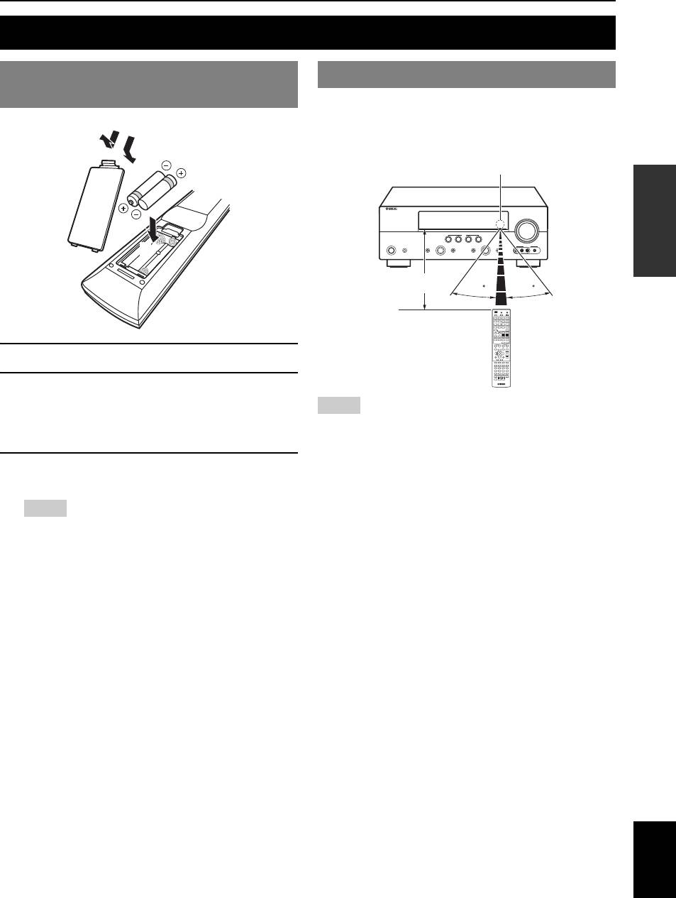
Installing batteries in the remote
Using the remote control
control
The remote control transmits a directional infrared ray. Be
sure to aim the remote control directly at the remote
control sensor on this unit during operation.
1
3
Remote control sensor window
PREPARATION
2
within 6 m
30 30
OPERATION
BASIC
1 Take off the battery compartment cover.
2 Insert the two supplied batteries (AAA, R03,
UM-4) according to the polarity markings (+
Notes
and –) on the inside of the battery
• Do not spill water or other liquids on the remote control.
OPERATION
ADVANCED
• Do not drop the remote control.
compartment.
• Do not leave or store the remote control in the following conditions:
– places of high humidity, such as near a bath
3 Snap the battery compartment cover back
– places of high temperatures, such as near a heater or stove
– places of extremely low temperatures
into place.
– dusty places
Notes
y
• You can operate external components with this remote control by setting
• Change all batteries if you notice the following conditions:
the remote control code. See page 55 for details.
INFORMATION APPENDIX
– the operation range of the remote control narrows.
ADDITIONAL
– the transmit indicator does not flash or is dim.
• Do not use old batteries together with new ones.
This may shorten the life of the new batteries or cause old batteries
to leak.
• Do not use different types of batteries (such as alkaline and
manganese batteries) together. Specification of batteries may be
different even though they look the same.
• If you find leaking batteries, discard the batteries immediately,
taking care not to touch the leaked material. If the leaked material
comes into contact with your skin or gets into your eyes or mouth,
rinse it away immediately and consult a doctor. Clean the battery
compartment thoroughly before installing new batteries.
• Dispose of the old batteries correctly in accordance with your local
regulations.
• If the remote control is without batteries for more than 2 minutes,
or if exhausted batteries remain in the remote control, the contents
of the memory may be cleared. In such a case, install new batteries
and set the remote control code.
English
9 En
Connections
Placing speakers
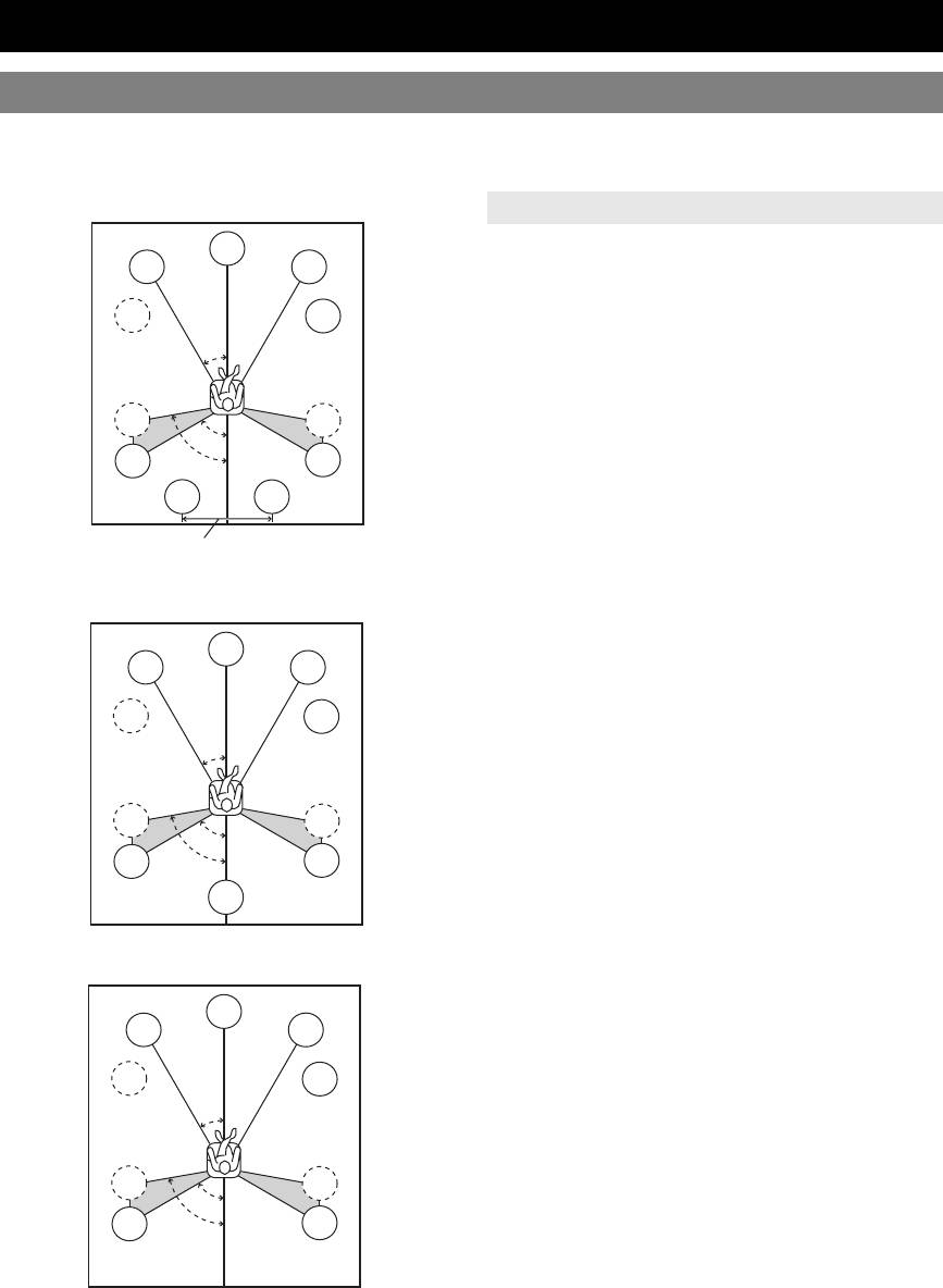
This unit supports up to 7.1-channel surround playback. We recommend the following speaker layout in order to obtain
the optimum surround effect.
7.1-channel speaker layout
Speaker channels
C
■ Front left and right speakers (FL and FR)
FL
FR
The front speakers output the front channel sounds (stereo
sound) and effect sounds. Place these speakers at an equal
SW
SW
distance from the ideal listening position. When using a
30˚
screen, the appropriate top positions of the speakers are
about 1/4 of the screen from the bottom.
■ Center speaker (C)
SL
SR
The center speaker outputs the center channel sounds
60˚
80˚
(dialog, vocals, etc.). Place it halfway between the left and
SL
SR
right speakers. When using a TV, place the speaker just
SBL
SBR
above or just under the center of the TV with the front
surfaces of the TV and the speaker aligned. When using a
30 cm or more
screen, place it just under the center of the screen.
■ Surround left and right speakers (SL and SR)
6.1-channel speaker layout
The surround speakers output effect sounds and surround
sounds. Place them at the rear left and rear right facing the
C
listening position.
FL
FR
To obtain a natural sound flow in the 5.1-channel speaker
layout, place them slightly further back than in the 7.1-
SW
SW
channel speaker layout.
30˚
■ Surround back left and right speakers (SBL
and SBR) / Surround back speaker (SB)
The surround back left and right speakers output rear
SL
SR
60˚
effect sounds. Place them at the rear of the room facing the
80˚
SL
SR
listening position at least 30 cm away from each other,
ideally at the same distance as that between the front left
SB
and right speakers.
In the 6.1-channel speaker layout, surround back left and
5.1-channel speaker layout
right channel sound signals are mixed down and output
from the single surround back speaker.
In the 5.1-channel speaker layout, surround back left and
C
FL
FR
right channel sound signals are output from the surround
left and right speakers.
SW
SW
■ Subwoofer (SW)
30˚
The subwoofer speaker outputs bass sounds and low-
frequency effect (LFE) sounds included in Dolby Digital
and DTS signals. Use a subwoofer with a built-in
SL
SR
amplifier, such as the Yamaha Active Servo Processing
60˚
Subwoofer System. Place it exterior to the front left and
80˚
SL
SR
right speakers facing slightly inward to reduce reflections
from a wall.
10 En
Connections
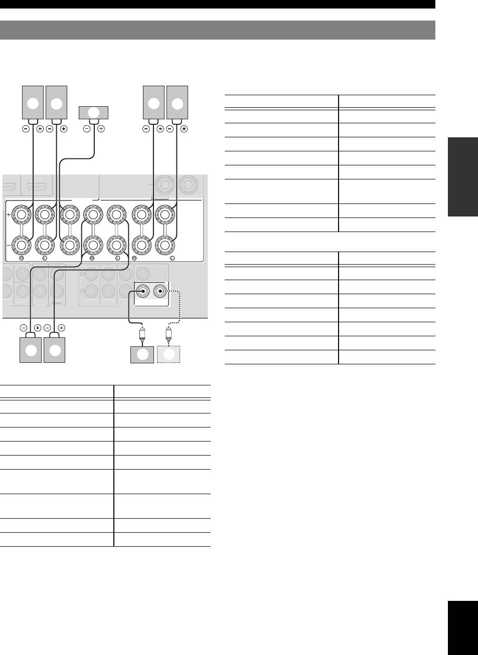
Connecting speakers
When you connect speakers, connect them to the respective jacks as follows, according to your speaker layout.
INTRODUCTION
y
• You can connect up to two subwoofers. When two subwoofers are connected, the same sound is output from them.
■ 6.1-channel
PREPARATION
OPERATION
■ 5.1-channel
BASIC
OPERATION
ADVANCED
■ 7.1-channel
Speakers Jacks on this unit
INFORMATION APPENDIX
ADDITIONAL
a Front speaker L FRONT (L)
b Front speaker R FRONT (R)
c Center speaker CENTER
d Surround speaker L SURROUND (L)
e Surround speaker R SURROUND (R)
f Surround back speaker L SURROUND
BACK/BI-AMP (L)
g Surround back speaker R SURROUND
BACK/BI-AMP (R)
h Subwoofer 1 SUBWOOFER 1
i Subwoofer 2 (optional) SUBWOOFER 2
English
11 En
EXTRA
SP
ZONE2
/
2
PRESENCE
SPEAKERS
SINGLE
FRONT
CENTER
SURROUND
SURROUND BACK/
BI-AMP
1
SUBWOOFER
2
O
UT
.
EXTRA SP
ZONE2
/
2
PRESENCE
Z
O
NE2
ZONE2
R.BA
C
K
SU
BW
OO
FE
R
N
A
PUT
U
DI
O
OU
T
FR
O
N
T
S
URROUND
SUR. BAC
K
P
RE
O
CENTER
UT
C
ENTER
S
IN
G
Speakers Jacks on this unit
b
a
g
f
c
a Front speaker L FRONT (L)
b Front speaker R FRONT (R)
c Center speaker CENTER
d Surround speaker L SURROUND (L)
e Surround speaker R SURROUND (R)
f Surround back speaker SURROUND
BACK/BI-AMP (SINGLE)
h Subwoofer 1 SUBWOOFER 1
i Subwoofer 2 (optional) SUBWOOFER 2
Speakers Jacks on this unit
LE
a Front speaker L FRONT (L)
b Front speaker R FRONT (R)
c Center speaker CENTER
d Surround speaker L SURROUND (L)
e Surround speaker R SURROUND (R)
h Subwoofer 1 SUBWOOFER 1
e d
h
i
i Subwoofer 2 (optional) SUBWOOFER 2
Connections
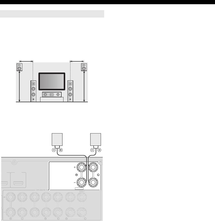
Presence speakers
You can connect presence speakers (PL/PR) that output
front effect sounds to this unit. With CINEMA DSP sound
field programs (see page 27) and their CINEMA DSP 3D
functions, a sound with a richer and more spacial presence
can be created. You can adjust the vertical position of
center sound such as a dialog (see page 47).
0.5 to 1 m0.5 to 1 m
PRPL
FL
FR
1.8 m 1.8 m
C
To use the presence speakers, connect them to the EXTRA
SP jacks and set “Extra SP Assign” in “Speaker Setup” in
the SETUP menu to “Presence” (see page 47).
EXTRA SP
ZONE2
/
PRESENCE
y
• Although you can connect both surround back speakers and presence
speakers to this unit, you cannot output sounds from those speakers at the
same time. This unit automatically selects speakers to output sounds
according to the selected input source and sound field program.
• You can connect Zone2 speakers with a multi-zone function to the
EXTRA SP jacks. For details, see page 53.
12 En
X
.
D
MI 3
HDMI 4
FR
O
N
T
C
ENTE
R
SU
RR
OU
N
D
SU
RR
OU
ND BA
C
K
/
B
I-AM
P
Presence
Presence
speaker R
speaker L
PR
PL
Connections
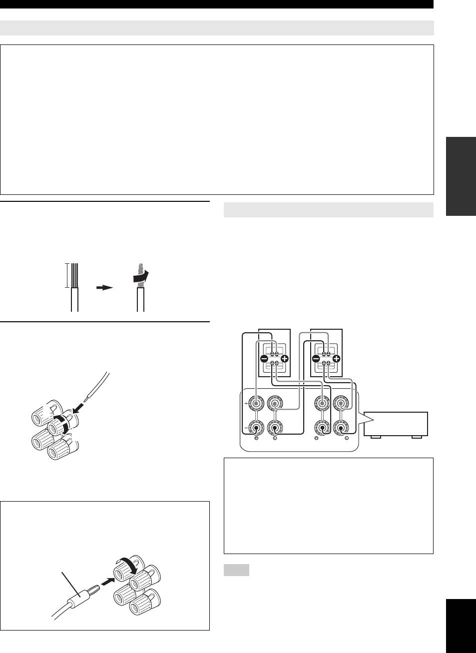
Connecting the speaker cable
Caution
INTRODUCTION
• A speaker cable is a pair of insulated cables running side by side in general. One of the cables is colored differently
or striped to indicate a polarity. Connect one end of the colored/striped cable to the “+” (red) terminal of this unit
and the other end to that of your speaker, and connect one end of the other cable to the “–” (black) terminal of this
unit and the other end to that of your speaker.
• Before connecting the speakers, be sure to disconnect the power cable.
• Do not let the bare speaker wires touch each other or any metal part of this unit. This could damage this unit and/or
speakers. If the circuit shorts out, “CHECK SP WIRES!” appears on the front panel display when this unit is turned
on.
• If your video monitor is a CRT, use magnetically shielded speakers. If images on the monitor are still distorted even
PREPARATION
when you use the magnetically shielded speakers, place the speakers away from the monitor.
• Use speakers with an impedance of 6-ohm or larger. Set speaker impedance in “ADVANCED SETUP” before
connecting the speakers. You can also use 4-ohm speakers as the front speakers when you set “SP IMP.” to
“6ΩMIN” (see page 58).
1 Remove approximately 10 mm of insulation
Using bi-amplification connections
from the end of each speaker cable and then
You can connect speakers that support bi-amplification
OPERATION
twist bare wires of the cable together so that
connections to this unit. To connect the speakers via a bi-
BASIC
they will not cause a short circuits.
amp connection, connect them to the FRONT jacks and
SURROUND BACK/BI-AMP jacks as illustrated.
10 mm
To enable the bi-amp connection, connect the power cable
to the wall outlet, display the ADVANCED SETUP menu
and set “BI AMP” to “ON” (see page 58).
Front speakers
OPERATION
ADVANCED
Right Left
2 Loosen the knob, insert the twisted bare
wires into the hole, and then tighten the
knob.
SINGLE
2
INFORMATION APPENDIX
ADDITIONAL
Red: positive (+)
1
Black: negative (–)
This unit
3
FRONT
SURROUND BACK/
BI-AMP
Caution
y
Before making bi-amplification connections, remove
• You can connect the presence speakers (see page 12) or the speakers in
the second zone (Zone2) (see page 53) to the EXTRA SP jacks.
any brackets or cables that connect a woofer with a
tweeter. Refer to the instruction manuals of speakers for
Connecting the banana plug (Except U.K.,
details.
Europe, Russian, Asia and Korea models)
When not making bi-amplification connections, make
Tighten the knob, and then insert the banana plug into
sure that the brackets or cables are connected before
the end of the terminal.
connecting the speaker cables.
Banana plug
Note
• You cannot use surround back speakers or extra speakers (presence and
Zone2 speakers) when bi-amplification connections are made.
English
13 En
Connections
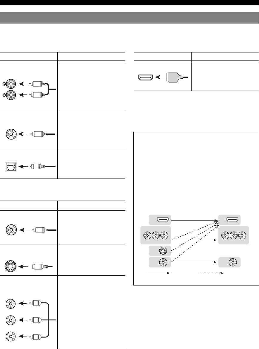
Information on jacks and cable plugs
This unit has the following input and output jacks. Use jacks and cables appropriate for components that you are
connecting.
■ Audio jacks
■ Video/audio jacks
Jack and cables Description
Jack and cables Description
AUDIO jacks To transmit conventional analog
HDMI jacks To transmit digital video and
(stereo) signals. Use stereo pin
digital audio signals. Use HDMI
(white)
cables. Connect red plugs to red
HDMI
cables.
HDMI
L
jacks (R) and white plugs to white
jacks (L).
R
y
AUDIO
• We recommend that you use a commercially available 19-pin HDMI
(red)
cable no longer than 5 meters (16 feet) with the HDMI logo printed on it.
• If you connect this unit to a component that has a DVI jack, an HDMI/
COAXIAL jacks To transmit coaxial digital audio
DVI-D cable is required.
• You can check error information on HDMI connections (see page 40).
signals. Use pin cables for digital
(orange)
audio signals.
C
A video signal input to this unit is output from the jacks
COAXIAL
in MONITOR OUT for the same kind of signal as the
input signal.
OPTICAL jacks To transmit optical digital audio
For example, if a VCR with a composite output signal
signals. Use optical fiber cables for
and a DVD player with a component video output
O
optical digital audio signals.
signal are connected, connect both VIDEO jack and
OPTICAL
COMPONENT VIDEO jack in MONITOR OUT to the
video monitor.
If an HDMI input compatible monitor is connected, this
unit automatically converts an analog signal that is
■ Video jacks
input from a video input jack to a digital video signal,
and then outputs it from the HDMI OUT jack.
Jack and cables Description
Input Output
VIDEO jacks To transmit conventional
HDMI
HDMI
composite video signals. Use video
VIDEO
pin cables.
V
COMPONENT
VIDEO
COMPONENT
VIDEO
(yellow)
PR
PB
Y
PR
PB
Y
S VIDEO jack To transmit S-video signals that
S VIDEO
include luminance (Y) and
S VIDEO
Cameroonians (C) components.
VIDEO
VIDEO
S
Use S-video cables.
Not converted Converted
COMPONENT VIDEO
To transmit component video
jacks
signals that include luminance (Y),
chrominance blue (PB) and
COMPONENT
VIDEO
chrominance red (PR) components.
PR
P
R
Use component video cables.
(red)
PB
P
B
(blue)
Y
Y
(green)
14 En
Connections
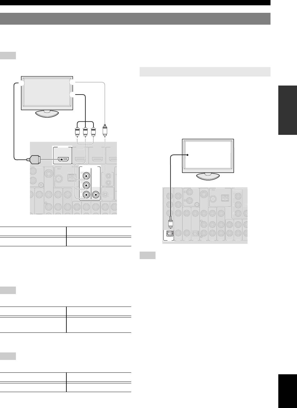
Connecting a video monitor
Connect a video monitor such as a TV or projector to an output jack of this unit. You can select one of the following three
INTRODUCTION
types according to the input signal format supported by the video monitor: HDMI OUT, COMPONENT VIDEO and
VIDEO (composite video).
Note
• Make sure that this unit and video monitor are unplugged from the AC wall outlets.
To output sound of a TV from this unit, connect an audio
output terminal of the TV to any of the AV 1-6 jacks.
PREPARATION
If the TV supports an optical digital output, we
recommend that you use the AV 1. Connecting to the AV 1
allows you to switch an input source to the AV input 1
with a just a single key operation using the SCENE
function (see page 24).
OPERATION
HDMI
OUT
BASIC
MONITOR OUT
COMPORNENT
VIDEO
P
R
P
B
VIDEO
Y
OPERATION
ADVANCED
■ To connect an HDMI video monitor
Jacks on components Jacks on this unit
a HDMI input HDMI OUT
INFORMATION APPENDIX
ADDITIONAL
y
Note
• This unit supports the HDMI control function. By connecting a TV that
supports the HDMI control, operations of this unit can be controlled with
• If the video monitor connected to this unit supports the HDMI control
the remote control of the TV. For details, see page 38.
function, we recommend that you connect its audio output jack to the
OPTICAL jack of the AV1 jacks of this unit. By doing so, this unit
automatically turns on and “TV” of SCENE is automatically selected
■ To connect component video monitor
when you turn on the video monitor. You can obtain the same result even
if you connect the audio output jacks to the AV2-6, AUDIO1-2 or V-
Note
AUX jacks by assigning those jacks to TV in advance (see page 24).
• Only video signals input from this unit via the COMPONENT VIDEO
jack are output from the COMPONENT VIDEO jack.
Jacks on components Jacks on this unit
b Component video output MONITOR OUT
(COMPONENT VIDEO)
■ To connect composite video monitor
Note
• Only video signals input from this unit via the VIDEO jacks are output
from the VIDEO jacks.
Jacks on components Jacks on this unit
English
c Video input (composite) MONITOR OUT (VIDEO)
15 En
T
RIGGER OU
T
12
V
0
.1
A
MAX.
ANTENNA
P
H
O
N
O
UNBAL.
FM
G
ND
G
N
D
A
M
I
N
OUT
REM
O
TE
S
.VIDE
O
D
E
O
HDMI
1
HDMI
2
HDMI
3
(
B
D
/
DVD
)
TV or projector
Outputting sound of a TV from this unit
a
c
b
YP
P
B
R
V
HDMI
ANTENN
OPTICAL
(
TV
)
A
V
1
A
P
H
O
N
O
U
NBAL.
F
M
G
ND
G
ND
A
M
CO
MP
O
NEN
T
VIDE
O
P
R
P
B
Y
M
O
NIT
O
R
OUT
P
R
P
B
Y
AV 2
CO
AXIAL
AV
3
(
CD
)
CO
AXIAL
O
PTI
C
AL
AV
4
A
V
5
AV
6
AV
O
U
T
A
U
DI
O1
S
.VIDE
O
A
UDI
O2
FRO
N
VIDE
O
V
IDE
CO
MP
O
RNENT
V
IDE
O
TV or projector
Digital output
(optical)
O
Connections
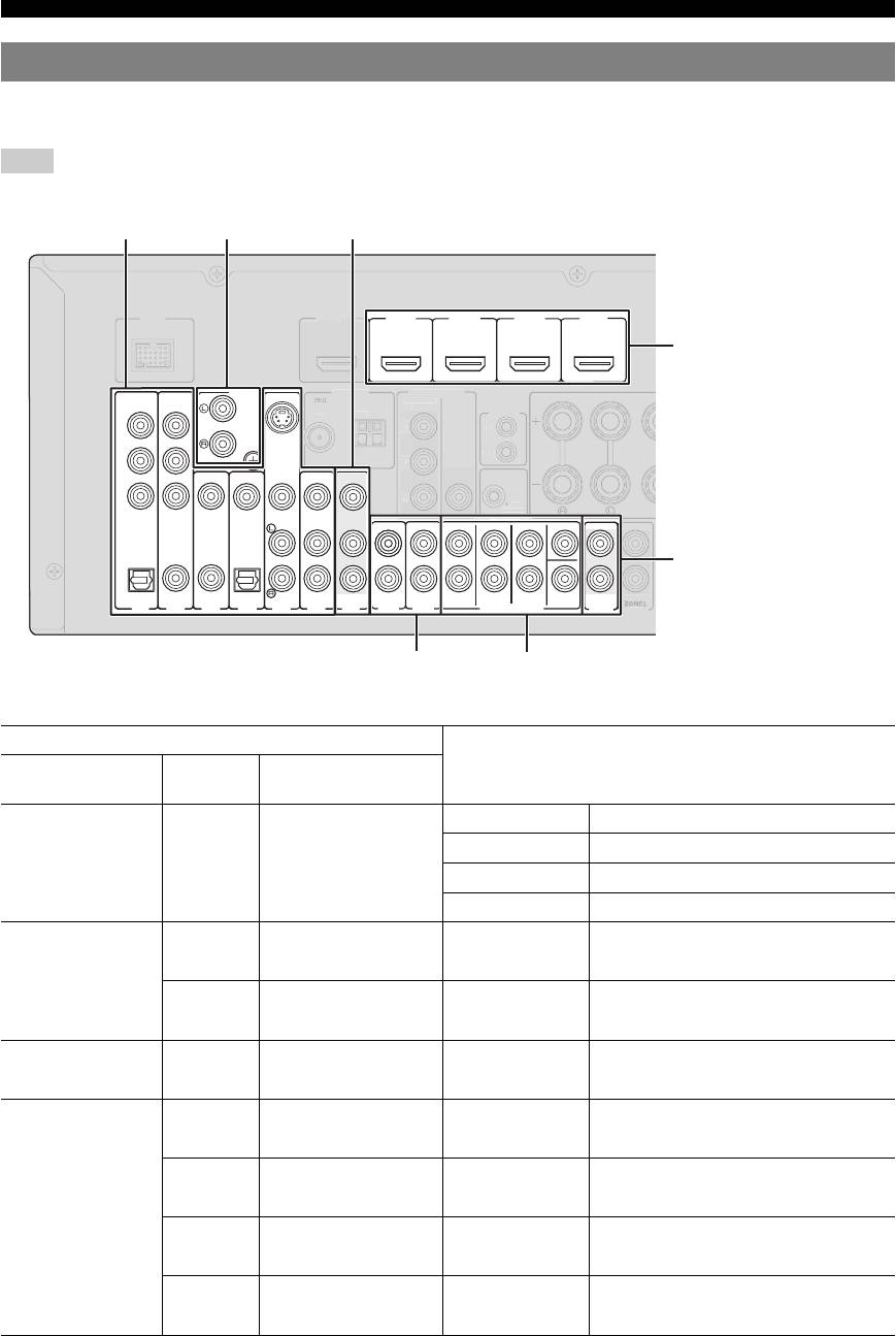
Connecting other components
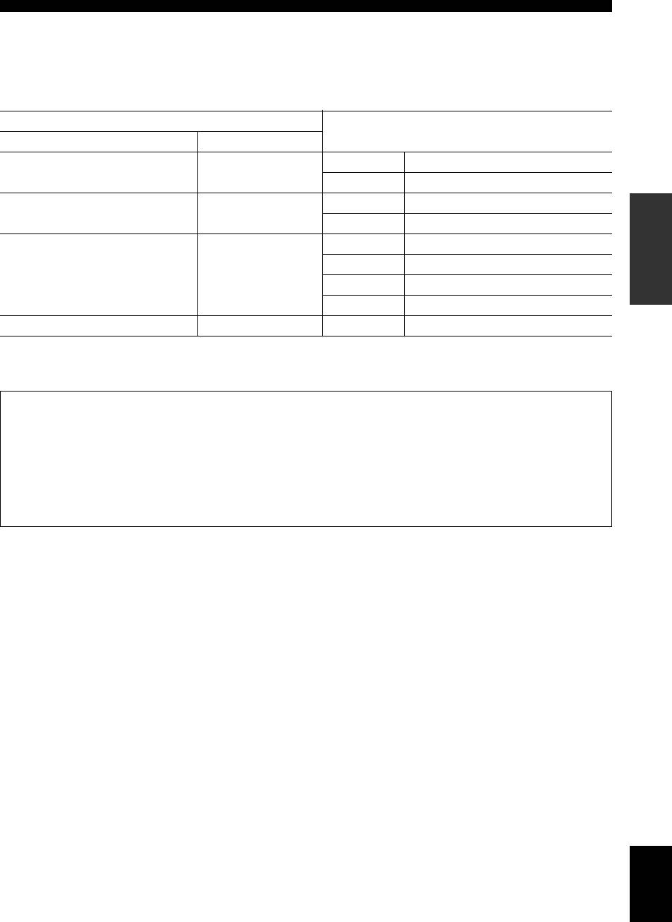
This unit has input and output jacks for respective input and output sources. You can reproduce sound and movies from
input sources selected with the front panel display or remote control.
Note
• Make sure that this unit and other components are unplugged from the AC wall outlets.
■ Audio and video player/Set-top box
Output jacks on the connected external component
Input sources/jacks of this unit
External
Signals Output jacks
components
External component
Audio/Video HDMI output HDMI1 (BD/DVD) HDMI 1
with HDMI output
HDMI2 HDMI 2
HDMI3 HDMI 3
HDMI4 HDMI 4
External component
Audio Optical digital output AV1 (TV) OPTICAL
with component video
Video Component video output COMPONENT VIDEO
output
Audio Coaxial digital output AV2 COAXIAL
Video Component video output COMPONENT VIDEO
External component
Audio Analog audio output AV5 AUDIO
with S-video output
Video S-video output S VIDEO
External component
Audio Coaxial digital output AV3 (CD) COAXIAL
with composite video
Video Composite video output VIDEO
output
Audio Optical digital output AV4 OPTICAL
Video Composite video output VIDEO
Audio Analog audio output AV5 AUDIO
Video Composite video output VIDEO
Audio Analog audio output AV6 AUDIO
Video Composite video output VIDEO
16 En
TRIGGER
OUT
HDMI 1 HDMI 2 HDMI 3 HDMI 4
(
BD/DVD
)
PHONO
COMPONENT
S.VIDEO
VIDEO
P
R
GND
P
B
VIDEO
Y
CENTER
OPTICAL
COAXIAL
COAXIAL
OPTICAL
(
TV
)
(
)
FRONT
SURROUND
SUR.BACK
SUBWOOFER
CD
AV
AUDIO
AV 1
AV 2
AV 3
AV 4
AV 5
AV 6
OUT
AUDIO1
AUDIO2
MULTI CH INPUT
OUT
O
UT
TRIGGER OUT
12
V
0.1
A
MAX.
A
NTENNA
UNBAL
.
FM
G
N
D
AM
P
R
P
B
Y
IN
O
U
T
REM
O
T
E
M
ONITOR OU
T
Z
O
NE2
ZONE2
HDMI
HDMI
V
IDE
O
CO
MP
O
RNENT
V
IDE
O
F
R
O
N
T
CE
OUT
OUT
Audio/video input
Phono input
(AV 1-6)
(PHONO)
Audio/video output (AV OUT)
DOCK
HDMI input
(HDMI 1-4)
Audio output
(AUDIO OUT)
Audio input (AUDIO 1-2)
Multi channel audio input (MULTI CH)
Connections
y
• Input sources in parentheses are recommended to connect to the respective jacks. If a component is compatible with the SCENE function, you can switch
the input source to that component with a single key operation using the SCENE function (see page 24).
• You can change the name of the input source displayed on the front panel display or the video monitor as necessary (see page 52).
• See page 53 on how to use ZONE2 OUT jack.
INTRODUCTION
■ Audio player
Output jacks on the connected external component
Input sources/jacks of this unit
External components Output jacks
External component with optical digital
Optical digital output AV 1 (TV) OPTICAL
output
AV 4 OPTICAL
External component with coaxial digital
Coaxial digital output AV 2 COAXIAL
PREPARATION
output
AV 3 (CD) COAXIAL
External component with analog audio
Analog audio output AV 5 AUDIO
output
AV 6 AUDIO
AUDIO 1 AUDIO
AUDIO 2 AUDIO
Turntable Analog audio output PHONO PHONO
OPERATION
y
BASIC
• When connecting a turntable with a low-output MC cartridge to the PHONO jack, use an in-line boosting transformer or MC-head amplifier.
• Connect your turntable to the GND terminal of this unit to reduce noise in the signal.
• We recommend connecting the coaxial digital output terminal of a CD player to the AV3 jack.
About audio/video output jacks
Among the analog audio and analog video signals input to this unit via input terminals, the audio/video signals of the
selected input sources are output from the AV OUT jack and AUDIO OUT jack. An HDMI input signal,
COMPONENT VIDEO input signal or digital audio input signal cannot be output. When using the AV OUT jacks or
OPERATION
ADVANCED
AUDIO OUT jacks, connect them as follows:
When using the AV OUT jacks: connect them to composite video and analog audio input jacks of an external
component.
When using the AUDIO OUT jacks: connect them to analog audio jacks of an external component.
INFORMATION APPENDIX
ADDITIONAL
English
17 En
Connections
Connecting a multi-format player or an
Connecting an external amplifier
external decoder
The same channel signals are output from the jacks of the
This unit has 8 sets of input jacks (FRONT L/R,
PRE OUT terminals as from their corresponding
CENTER, SURROUND L/R, SUR. BACK and
SPEAKERS terminals. When connecting an external
SUBWOOFER) to input multi-channel analog sound
power amplifier (pre-main amplifier) to enhance speaker
signals. If your playback component, such as a DVD
output, connect the input terminals of the power amplifier
player or SACD player, has multi-channel analog output
to the PRE OUT terminals of this unit.
capability, you can enjoy up to 7.1-channel multi-channel
Note
sound. To output multi-channel sound, connect the audio
• When a component is connected to the PRE OUT terminals, do not
output jacks of your playback component to the MULTI
connect speakers to the SPEAKERS terminals corresponding to those
CH INPUT jacks of this unit, and set the input source of
PRE OUT terminals.
this unit to “MULTI CH.” For details on how to change
input sources, see page 24.
CENTERSINGLE
CENTER
FRONT
SURROUND
SUR.BACK
SUBWOOFER
FRONT
SURROUND
SUR. BACK
1
SUBWOOFER
2
MULTI CH INPUT
PRE OUT
LRLR LR
a FRONT (PRE OUT) jacks
Front out
out
Surround
back out
Surround
Subwoofer out
Center out
Front channel output jacks.
b SURROUND (PRE OUT) jacks
Surround channel output jacks.
c SUR. BACK (PRE OUT) jacks
Surround back output jacks. When you only connect one
external amplifier for the surround back channel, connect it to
the SUR. BACK (SINGLE) jack.
Multi-format player/External decoder
(7.1-channel output)
y
• To output surround back channel signals through these jacks, set
“Sur.B L/R SP” to any parameter except for “None” in “Speaker
Notes
Setup” (see page 48).
• When you select “MULTI CH” as the input source, the digital sound field
d CENTER (PRE OUT) jack
processor is automatically disabled.
• Since this unit does not redirect signals input at the MULTI CH INPUT
Center channel output jack.
jacks to accommodate for missing speakers, connect at least a 5.1-
e SUBWOOFER (PRE OUT) 1/2 jack
channel speaker system when using this feature.
Connect a subwoofer with a built-in amplifier. When two
• When the input source is switched to “MULTI CH,” images input from a
subwoofers are connected, the same sound is output from them.
component connected to “AV1-6” or “V-AUX” can be displayed on a
video monitor (see page 41). If your DVD player does not support multi-
channel digital output, connect it to these input jacks.
18 En
abc d
e
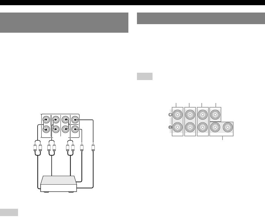
Connections
Using REMOTE IN/OUT jacks
When the components are the Yamaha products and have
INTRODUCTION
the capability of the transmission of the remote control
The V-AUX terminals on the front panel are useful for
signals, connect the REMOTE IN and REMOTE OUT
connecting a camcorder, a game console or a portable
jacks to the remote control input and output jack with the
music player to this unit. Be sure to turn down the volume
monaural analog mini cable as follows.
of this unit and other components before making
connections.
PREPARATION
REMOTE
IN
OUT
OPERATION
BASIC
y
• If your Yamaha component supports the SCENE link playback function,
remote connection automatically starts playback when you press
OPERATION
ADVANCED
MSCENE (or iSCENE) to select a SCENE.
• If the component connected to the REMOTE OUT jack is not a Yamaha
product, set “SCENE IR” in the ADVANCED SETUP menu to “OFF”
(see page 58).
Connecting a Yamaha iPod universal
dock or Bluetooth™ wireless audio
y
receiver
INFORMATION APPENDIX
• To connect a component to the PORTABLE jack, use a 3.5 mm stereo
ADDITIONAL
mini plug cable.
This unit has the DOCK jack, to which you can connect a
• When external components are connected both the PORTABLE jack and
Yamaha iPod universal dock (YDS-11, sold separately) or
AUDIO jack, sound input from the PORTABLE jack is output.
a Bluetooth wireless audio receiver (YBA-10, sold
separately). You can play an iPod or a Bluetooth
component with this unit by connecting it to the DOCK
jack.
Use a dedicated cable for connection between the dock/
receiver and this unit.
English
19 En
P
R
P
B
Y
MO
NIT
O
R
OUT
H
DMI
1
HDMI
2
H
DMI
3
H
DMI 4
B
D
/
DVD
)
V
IDE
O
CO
MP
O
RNENT
V
IDE
O
Remote
Remote
control out
control in
Infrared signal
Yamaha component
receiver or Yamaha
(CD or DVD player, etc.)
component
D
OC
K
ANTENNA
PH
O
N
O
UNBAL.
FM
G
N
D
G
N
D
AM
CO
MP
O
NENT
V
IDE
O
P
R
S
.VIDE
O
HDMI
HDMI
OUT
OUT
Connecting a camcorder or portable
audio player
VIDEO
AUX
VIDEO
AUDIO
PORTABLE
Yamaha iPod universal
dock/Bluetooth wireless
audio receiver
TU
NIN
G
S
TRAI
G
H
T
M
I
NP
UT
P
URE DIRE
C
T
O
PTIMIZER
MI
C
M
EM
O
R
Y
V
O
L
U
M
E
PRESET
EFFECT
l
h
l
h
B
D
/
DV
D
TV
CD
R
ADI
O
SC
FM
ENE
AM
VIDEO
AUX
VIDEO
AUDI O
PORTABLE
Video output
output
Analog audio
output
Analog audio
V
L
R
Game console/Camcorder Music player
Connections
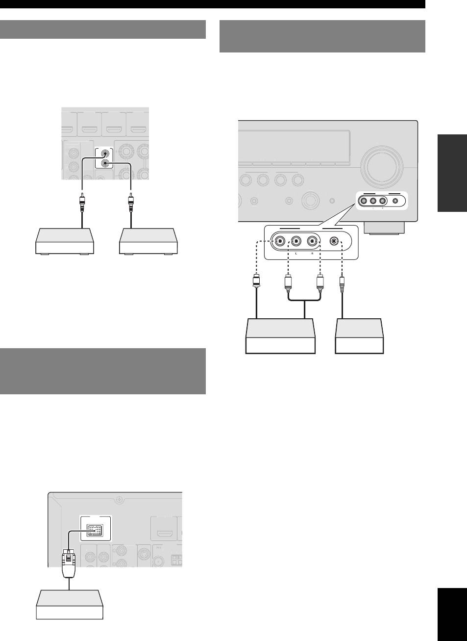
Connecting the FM and AM antennas
An indoor FM antenna and an AM loop antenna are
After all connections are complete, plug the AC power
supplied with this unit. Connect these antennas properly to
cable of this unit into an AC wall outlet.
the respective jacks.
ANTENNA
UNBAL.
FM
GND
AM
TRI
y
• The supplied antennas are normally sensitive enough to obtain good
1 Press AMAIN ZONE ON/OFF (or
reception.
• Position the AM loop antenna away from this unit.
pPOWER) to turn on this unit.
• If you cannot get good reception, we recommend that you use an outdoor
antenna. For more details, consult the nearest authorized Yamaha dealer
2 Press AMAIN ZONE ON/OFF (or
or service center.
• Always use the AM loop antenna even when the outdoor antenna is
pPOWER) again to turn off this unit
connected.
(standby).
Assembling the AM loop antenna
y
• This unit needs a few seconds until ready to play back.
• You can also turn on this unit by pressing MSCENE (or iSCENE).
• This unit consumes a small amount of electricity even during standby.
We recommend disconnecting the power cable from the AC wall outlet.
Connecting the AM loop antenna
The wires of the AM loop antenna have no polarity. You
can connect either wire to the AM terminal and the other
to the GND terminal.
20 En
GG
ER
OU
PH
12V
0.1A MAX.
T
O
N
O
G
N
D
CO
MP
O
NENT
V
IDEO
P
R
P
B
Y
IN
O
U
T
R
EM
O
T
E
M
O
NIT
O
R
O
UT
P
R
P
B
Y
S
.VIDE
O
VIDE
O
VIDE
O
CO
MP
O
RNEN
T
VIDE
O
F
R
O
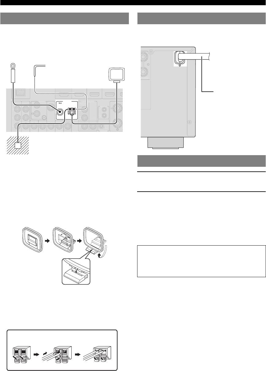
Connecting the power cable
Indoor FM antenna
Outdoor AM antenna
AM loop
Connect a 5 to 10 m vinyl-
antenna
covered wire, and extend
it outdoors (use the AM
loop antenna together
with this antenna).
Ground (GND terminal)
The GND terminal is not for earth grounding.
To reduce noises, connect a ground bar or a
vinyl-covered wire with a copper plate at its tip,
and place it in the moist ground.
Turning this unit on and off
Caution
Do not unplug this unit while it is turned on. Doing so
may damage this unit or cause the settings of this unit
to be saved incorrectly.
Press and hold ReleaseInsert
/
P
RE
S
EN
C
To the AC wall outlet
E
Power cable
Optimizing the speaker setting for your listening room (YPAO)
This unit has a Yamaha Parametric Room Acoustic Optimizer (YPAO). With the YPAO, this unit automatically adjusts the
output characteristics of your speakers based on speaker position, speaker performance, and the acoustic characteristics of
the room. We recommend that you first adjust the output characteristics with the YPAO when you use this unit.
INTRODUCTION
“MIC ON. View OSD MENU” appears on the front panel
Notes
display. The following menu screen appears on the video
• Loud test tones may be output during the automatic
monitor.
setup procedure. Do not allow small children to enter
the room during the procedure.
• To achieve the best results, make sure the room is as
quiet as possible while the automatic setup procedure
PREPARATION
is in progress. If there is too much ambient noise, the
results may not be satisfactory.
y
• You can manually adjust the output characteristics of your speakers
with “2 Manual Setup” in the SETUP menu. For details, see page 47.
y
• You can bring up the above menu screen from the SETUP menu
(see page 47).
Using Auto Setup
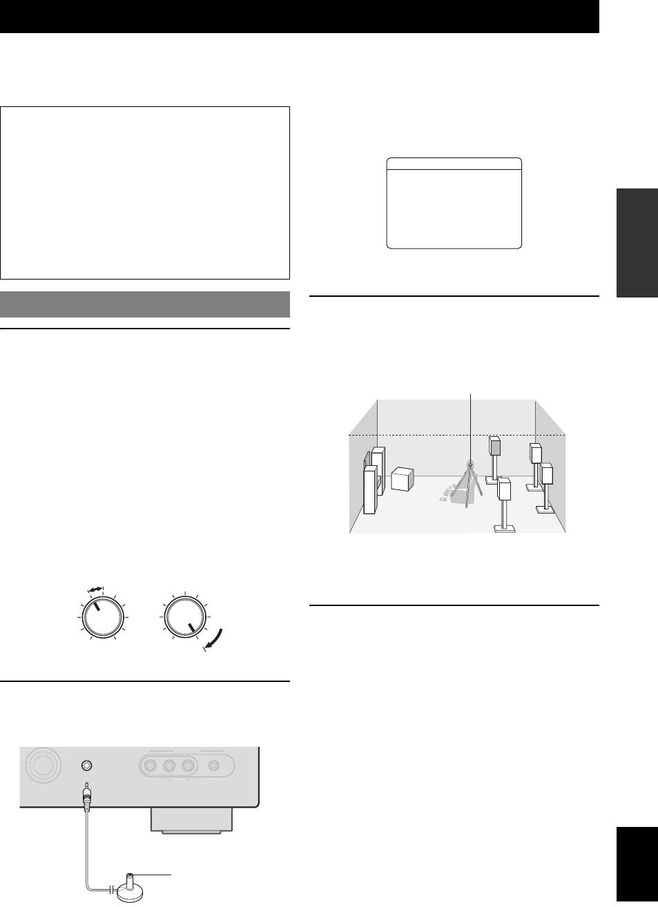
3 Place the optimizer microphone at your
OPERATION
normal listening position on a flat level
BASIC
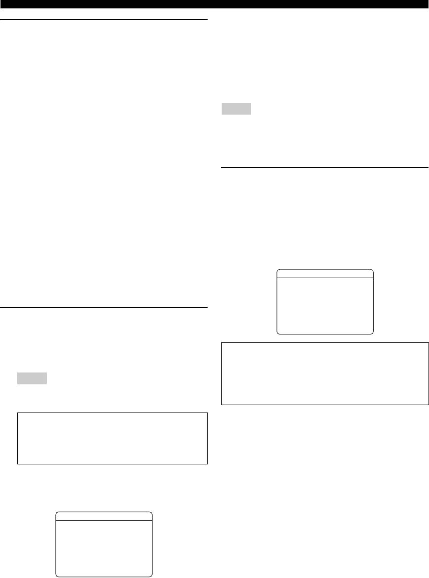
1 Check the following points.
surface with the omni-directional
Before starting the automatic setup, check the
microphone heading upward.
following.
• All speakers and subwoofer are connected
properly.
• Headphones are disconnected from this unit.
• The video monitor is connected properly.
OPERATION
ADVANCED
• This unit and the video monitor are turned on.
• This unit is selected as the video input source of the
video monitor.
• The connected subwoofer is turned on and the
volume level is set to about half way (or slightly
less).
• The crossover frequency controls of the connected
INFORMATION APPENDIX
y
ADDITIONAL
subwoofer are set to the maximum.
• It is recommended that you use a tripod or something similar to fix the
CROSSOVER/
optimizer microphone at the same height as your ears would be when
VOLUME
HIGH CUT
seated in your listening position. You can fix the optimizer microphone to
the tripod with the attaching screw of the tripod.
4 When the speakers are connected to EXTRA
SP jacks, press kCursor k repeatedly to
MIN MAX
MIN MAX
select “Extra SP Assign,” and then press
Subwoofer
kCursor l / h to select how to use EXTRA
SP jacks from “Zone2,” “Presence” or
2 Connect the supplied optimizer microphone
“None.”
to the OPTIMIZER MIC jack on the front
If this unit does not work when you press kCursor,
panel.
press jSETUP once and then operate this unit.
VIDEO
AUDI
English
21 En
O
PO
RTABL
E
VIDE
O
A
UX
1 AutoSetup
ExtraSPAssign
>Zone2Presence
None
EQ Type;;;;Natural
. Start
[
[]/[]:Up/Down
[
[ENTER]:Start
Optimizer microphone
OPTIMIZER
MIC
Optimizer microphone
Optimizing the speaker setting for your listening room (YPAO)
DIST
5 To select a sound character for adjustment,
Displays the speaker distance from the listening position
press kCursor n to select “EQ Type” and
in the following order:
then press kCursor l / h.
Closest speaker distance/Farthest speaker distance
If this unit does not work when you press kCursor,
LVL
press jSETUP once and then operate this unit.
Displays the speaker output levels in the following order:
This unit has a parametric equalizer that adjusts the
Lowest speaker output level/Highest speaker output level
output levels for each frequency range. The equalizer
is adjusted to produce a cohesive sound field based on
Notes
automatically measured speaker characteristics.
• If “ERROR” appears on the video monitor during the automatic setup
In “EQ Type,” you can select the following
procedure, measurement is canceled and the type of error is displayed.
For details, see “When an error message is displayed during
parametric equalizer characteristics suitable for the
measurement” (see page 23).
desired sound characteristics.
• If problems occur during measurement, “WARNING (XX)” (xx indicates
the number of warning) appears above “RESULT” (see page 23).
Natural
Adjusts all speakers to achieve natural sound. Select
7 Press kENTER.
this if sounds in the high frequency range seem too
The speaker characteristics are adjusted according to
strong when “EQ Type” is set to “Flat.”
measurement results.
Flat
To cancel the operation, press kCursor l / h to
Adjusts each speaker to obtain the same
select “Cancel” and press kENTER.
characteristics. Select this if your speakers have
When the following screen appears, remove the
similar qualities.
optimizer microphone. The automatic setup
Front
procedure is now complete.
Adjusts each speaker to obtain the same
characteristics as the front left and right speakers.
1 AutoSetup
Select this if your front left and right speakers have
AUTOSETUPComplete
significantly better qualities than the other speakers.
DisconnectMicrophone
6 Press kCursor n to select “Start” and then
PRESS[ENTER]
press kENTER to start the setup procedure.
[SETUP]:Exit
A countdown starts and a measurement starts in 10
seconds. A loud test tone is output during
The optimizer microphone is sensitive to heat. Store it
measurement.
in a cool place and away from direct sunlight after
measurement. Do not leave it in a place where it will be
Notes
subjected to high temperatures such on an AV
• During the automatic setup procedure, do not perform any
operation on this unit.
component.
• To cancel the automatic setup procedure, press kCursor k.
y
Measurement takes about 3 minutes. To obtain
• If you do not want to apply the measurement results, select “Cancel.”
precise results, stay where you will not disturb the
• Perform the automatic setup procedure again if you change the number
or positions of speakers.
measurement, such as to the side of or behind the
• If you press kENTER before removing the optimizer microphone,
speakers or outside the room.
“1 Auto Setup” of “Speaker Setup” in the SETUP menu (see page 47) is
displayed.
When measurement is successfully completed,
“YPAO Complete” appears on the front panel display
and the results appear on the video monitor.
1 AutoSetup
RESULT
SP:3/4/0.1
DIST:2.50/3.00m
LVL:-3.5/+4.5dB
. >Set Cancel
[]/[]:Select
p[
[ENTER]:Finish
SP
Displays the number of speakers connected to this unit in
the following order:
Total of Front, Center, and Presence/Total of Surround and
Surround Back/Subwoofer
22 En

Optimizing the speaker setting for your listening room (YPAO)
When an error message is displayed
during measurement
INTRODUCTION
If a problem occurs during measurement, “WARNING” is
Press kCursor n once, and select “Retry” or
displayed on the result display screen. Check the error and
“Exit” using kCursor l / h and then press
solve the problems.
kENTER.
ERROR
Don't
PREPARATION
y
• See page 67 for details on warning messages.
Retry
• Optimization will not be performed while a warning message is
Performs the automatic setup procedure again.
displayed. We recommend that you solve the problem and perform the
automatic setup procedure again.
Exit
Terminates the measurement and the automatic setup
1 If “→” is displayed on the left of “WARNING”
OPERATION
procedure.
on the result display screen, press
BASIC
y
kENTER.
• See page 66 for details on error messages.
Details of the warning message are displayed. If there
• When “E-5:NOISY” appears, you can continue measurement. To
continue measurement, select “Proceed.” However, we recommend that
are multiple warning messages, you can display the
you solve the problem first and then perform measurement again.
next message using kCursor h.
2 To return to the top result display, press
OPERATION
kENTER again.
ADVANCED
INFORMATION APPENDIX
ADDITIONAL
English
23 En
When a warning message is displayed
after measurement
WARNING
W-1:OUTOFPHASE
Reversechannel
.E-9:USER CANCEL
FL---
operate
CENTER
any function
------
SL---
SBL---
>RetryExit
[]/[]:Select
p[
[ENTER]:Return
[]/[]:Select
p[
[ENTER]:Return


