Yamaha RX-V765 Black: INTRODUCTION
INTRODUCTION: Yamaha RX-V765 Black

INTRODUCTION
Features
■ Built-in 7-channel power amplifier
• DTS, DTS 96/24, DTS-ES Matrix 6.1,
• Minimum RMS Output Power (20 Hz-20 kHz, 0.08%
DTS-ES Discrete 6.1
THD, 8 Ω)
• Dolby Pro Logic, Dolby Pro Logic II,
• FRONT L/R: 95 W + 95 W
Dolby Pro Logic IIx
• CENTER: 95 W
• DTS NEO:6
• SURROUND L/R: 95 W + 95 W
• DSD
• SURROUND BACK L/R: 95 W + 95 W
■ Sophisticated FM/AM tuner
■ Speaker/Preout outputs
• 40-station random and direct preset tuning
• Speaker jacks (7-channel + presence 2-channel), preout
• Automatic preset tuning
output jacks (7-channel, and subwoofer preout jack x 2)
• Radio Data System tuning
■ Input/Output terminals
■
HDMI™
(High-Definition Multimedia Interface)
Input terminals
• HDMI interface for standard, enhanced or high-
• HDMI input x 4
definition video as well as multi-channel digital audio
• Audio/Video input
– Automatic audio and video synchronization (lip sync)
[Audio] Digital input (coaxial) x 2, digital input
information capability
(optical) x 2, analog input x 2
– Deep Color video signal (30/36 bit) transmission
[Video] Component video x 2, S-video x 1,
capability
composite video x 4
– “x.v.Color” video signal transmission capability
• Audio input (analog) x 2
– High refresh rate and high resolution video signals
• Phono input x 1
capability
• Multi-channel audio input x 1
– High definition digital audio format signals capability
• Dock input x 1
• Analog video to HDMI digital video up-conversion
• V-AUX input
(composite video → HDMI, component video →
[Audio] Analog x 1, stereo mini jack x 1
HDMI) capability for monitor out
[Video] Composite video x 1
• Analog video input up-scaling for HDMI digital video
Output terminals
output 576i or 576p → 720p, 1080i or 1080p
• Monitor output
• HDMI control capability
[Audio/Video] HDMI x 1
■ DOCK jack
[Video] Component video x 1, Composite video x 1
• DOCK jack to connect a Yamaha iPod universal dock
• Audio/Video output
(such as YDS-11, sold separately) or Bluetooth wireless
[Audio] Analog x 1
audio receiver (such as YBA-10, sold separately)
[Video] Composite video x 1
• Audio output
■ Automatic speaker setup features
Analog x 1
• “YPAO” (Yamaha Parametric Room Acoustic
• Zone2 output
Optimizer) for automatically optimizing speaker
Analog x 1
outputs suitable for listening environments
Other terminals
■ Other features
Remote input x 1, Remote output x 1
• 192-kHz/24-bit D/A converter
Trigger output x 1
• OSD (on-screen display) menus that allow you to
optimize this unit to suit your individual audiovisual
■ Proprietary Yamaha technology for the
system
creation of sound fields
• Pure Direct mode for pure hi-fi sound for all sources
• CINEMA DSP 3D
• Adaptive dynamic range controlling capability
• Compressed Music Enhancer mode
• SCENE function that allows you to change input
• Virtual CINEMA DSP
sources and sound field programs with one key
• SILENT CINEMA™
• Sleep timer
■ Digital audio decoders
• Multi-zone function
• Dolby TrueHD, Dolby Digital Plus
• DTS-HD Master Audio, DTS-HD High Resolution
Audio, DTS Express
• Dolby Digital, Dolby Digital EX
2 En
About this manual
• Some operations can be performed by using either the keys on the front panel or the ones on the remote control. In case the key names differ between
the front panel and the remote control, the key name on the remote control is given in parentheses.
• This manual is printed prior to production. Design and specifications are subject to change in part as a result of improvements, etc. In case of
INTRODUCTION
differences between the manual and product, the product has priority.
• “AMAIN ZONE ON/OFF” or “eHDMI 1” (example) indicates the name of the parts on the front panel or the remote control. Refer to the
“Controls diagram” or “Part names and functions” on page 4 for the information about each position of the parts.
• y indicates a tip for your operation.
• ☞ indicates the page describing the related information.
Bluetooth™
Bluetooth is a registered trademark of Bluetooth SIG and is used by
Yamaha in accordance with a license agreement.
PREPARATION
Manufactured under license from Dolby Laboratories.
Dolby, Pro Logic and the double-D symbol are trademarks of Dolby
Laboratories.
“HDMI,” the “HDMI” logo and “High-Definition Multimedia
Interface” are trademarks, or registered trademarks of HDMI
Licensing LLC.
Manufactured under license under U.S. Patent No’s:
x.v.Color™
5,451,942;5,956,674;5,974,380;5,978,762;6,226,616;6,487,535 &
“x.v.Color” is a trademark of Sony Corporation.
other U.S. and worldwide patents issued & pending. DTS is a
OPERATION
registered trademark and the DTS logos, Symbol, DTS-HD and DTS-
BASIC
HD Master Audio are trademark of DTS, Inc. © 1996-2007 DTS, Inc.
All Rights Reserved.
“SILENT CINEMA” is a trademark of Yamaha Corporation.
iPod™
“iPod” is a trademark of Apple Inc., registered in the U.S. and other
countries.
OPERATION
ADVANCED
Supplied accessories
Check that you received all of the following parts.
• Remote control (see page 9)
• Batteries (AAA, R03, UM-4) x 2 (see page 9)
• Optimizer microphone (see page 21)
• AM loop antenna (see page 20)
• Indoor FM antenna (see page 20)
INFORMATION APPENDIX
ADDITIONAL
• Controls diagram
English
3 En
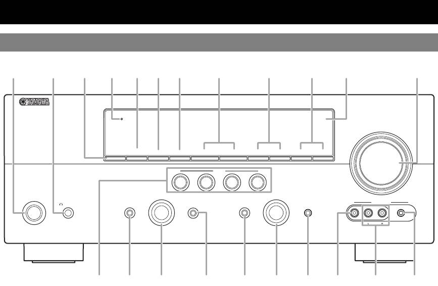
Part names and functions
Front panel
AB
C
D
E
GF JIH
K
L
HDMI
THROUGH
VOLUME
ON/OFF
ZONE2
CONTROL
ZONE2
INFO
MEMORY
l
PRESET
h
FM AM
l
TUNING
h
SCENE
BD/DVD
TV
CD
RADIO
MAIN
ZONE
PROGRAM INPUT
PHONES
TONE
CONTROL
STRAIGHT
PURE DIRECT
OPTIMIZER
MIC
VIDEO
AUX
ON/OFF
SILENT
CINEMA
EFFECT
VIDEO
AUDI O
PORTABLE
M
N Q SO R
U VTP
A MAIN ZONE ON/OFF
N TONE CONTROL
Turns this unit on and off (see page 20).
Adjusts high-frequency/low-frequency output of speakers/
headphones (see page 24).
B PHONES jack
For connecting headphones (see page 26).
O PROGRAM selector
Changes sound field programs (see page 27).
C ZONE2 ON/OFF
Switches Zone2 between on and off (see page 54).
P STRAIGHT
Toggles between the selected sound field program and straight
D HDMI THROUGH
decoding mode (see page 30).
During standby, lights up under the following conditions:
• the HDMI control function is enabled (see page 50).
Q PURE DIRECT
• an HDMI signal input to this unit passes through this unit and
Changes mode to Pure Direct mode (see page 25). This key
output (see page 50).
lights up when Pure Direct mode is on.
E ZONE2 CONTROL
R INPUT selector
Enables operation of a receiver set in Zone2, including input
Selects an input source (see page 24).
source switching, volume control and tuner operation, with the
S OPTIMIZER MIC jack
main amplifier or remote control after this key is pressed.
For connecting the supplied optimizer microphone and adjusting
F INFO
output characteristics of speakers (see page 21).
Changes information on the front panel display, such as input
T VIDEO (VIDEO AUX) jack
source and sound field program name (see page 26).
For connecting the video output cable of a camcorder or game
G MEMORY
console (see page 19).
Registers FM/AM stations as preset stations (see page 32).
U AUDIO L/R (VIDEO AUX) jack
H PRESET l / h
For connecting the audio output cable of a camcorder or game
Selects an FM/AM preset station (see page 32).
console (see page 19).
I FM/AM
V PORTABLE (VIDEO AUX) jack
Changes the tuner bands between FM and AM.
For connecting the audio output cable of a portable music player
(see page 19).
J TUNING l / h
Changes FM/AM frequencies.
K Front panel display
Displays information on this unit (see page 6).
L VOLUME control
Controls the volume of this unit (see page 24).
M SCENE
Switches between linked sets of input sources and sound field
programs (see page 24).
4 En
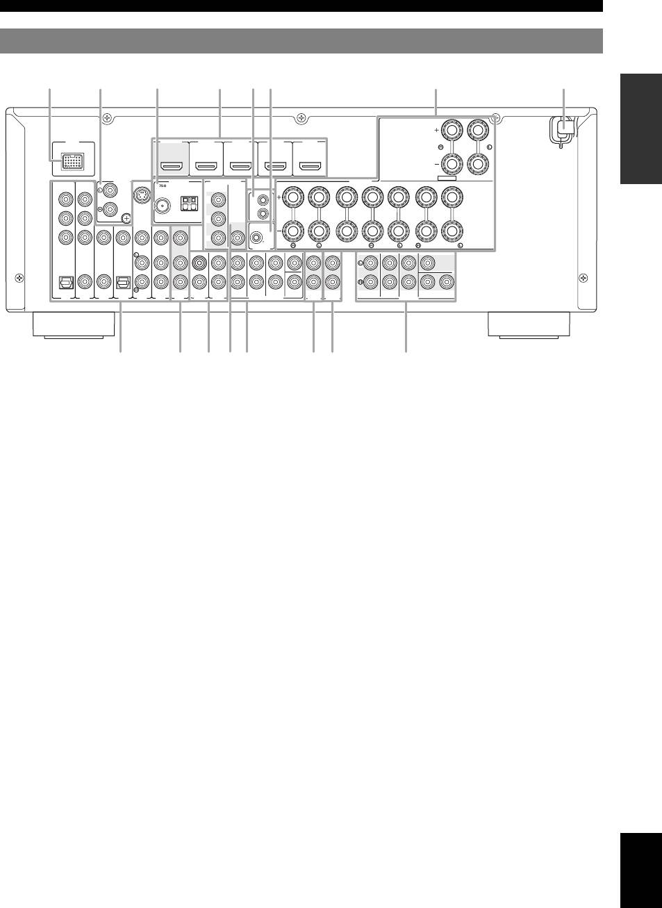
Part names and functions
Rear panel
INTRODUCTION
a
b
c
d
e f
g
h
DOCK
HDMI
OUT
HDMI 1 HDMI 2 HDMI 3 HDMI 4
(
BD/DVD
)
EXTRA SP
ZONE2
/
PRESENCE
S.VIDEO
ANTENNAPHONO
MONITOR OUT
SPEAKERS
COMPONENT
SINGLE
VIDEO
UNBAL.
COMPORNENT
VIDEO
FM
GND
AM
REMOTE
PR
PR
IN
PREPARATION
GND
OUT
PB
PB
VIDEO
VIDEO
Y
Y
12V
0.1A MAX.
FRONT
CENTER
SURROUND
SURROUND BACK/
TRIGGER OUT
BI-AMP
CENTER
SINGLE
CENTER
OPTICAL
COAXIAL
COAXIAL
OPTICAL
(
TV
)
(
)
FRONT
SURROUND
SUR.BACK
SUBWOOFER
FRONT
SURROUND
SUR. BACK
1
SUBWOOFER
2
A
V
1
AV 2
AV 3
CD
AV 4
AV 5
AV 6
OUT
AV
AUDIO1
AUDIO2
MULTI CH INPUT
AUDIO
OUT
ZONE2
ZONE2
OUT
PRE OUT
OPERATION
BASIC
ij mknop
l
a DOCK jack
l MONITOR OUT terminals
For connecting a Yamaha iPod universal dock (YDS-11, sold
Outputs video signals from this unit to a video monitor, such as
separately) or a Bluetooth wireless audio receiver (YBA-10,
a TV (see page 15).
sold separately) (see page 19).
m MULTI CH INPUT terminals
b PHONO jacks
For connecting a player that supports a multi-channel output
OPERATION
ADVANCED
For connecting a turntable (see page 17).
(see page 18).
c ANTENNA jacks
n AUDIO OUT jacks
For connecting supplied FM and AM antennas (see page 20).
Outputs audio signals from a selected analog input source to an
d HDMI OUT/HDMI 1-4 jacks
external component (see page 17).
For connecting an HDMI-compatible video monitor or external
o ZONE2 OUT jacks
components for HDMI inputs 1-4 (see page 16).
Outputs sound of this unit to an external amplifier set in a
different zone.
e REMOTE IN/OUT jacks
INFORMATION APPENDIX
For connecting an external component that supports the remote
p PRE OUT terminals
ADDITIONAL
control function (see page 19).
For connecting a subwoofer with built-in amplifier (see page 11)
or an external power amplifier (see page 18).
f TRIGGER OUT jack
For connecting an external terminal with a trigger input terminal
to operate it linked with operation of this unit. For example,
when an electric screen that supports a trigger input is
connected, it opens and closes linked with operation of an input
source selected in this unit.
g SPEAKERS terminals
For connecting front right and left, center, surround and
surround back speakers (see page 11). Connect the presence
speakers (see page 12) or the speakers for Zone2 (see page 53)
to the EXTRA SP jacks.
h Power Cable
Connect this cable to an AC wall outlet (see page 20).
i AV 1-6 jacks
For connecting external components for audio/video inputs 1-6
(see page 16).
j AV OUT jacks
Outputs audio/video signals from a selected analog input source
to an external component (see page 17).
English
k AUDIO 1/2 jacks
For connecting external components for audio inputs 1-2
(see page 17).
5 En
Part names and functions
Front panel display
SLEEP
VOL.
STEREO
ZONE
3
TUNED
2
MUTE
SW
PL PR
C
LR
SL SR
SBL SB SBR
a HDMI indicator
Lights up during normal communication when HDMI is
selected as an input source.
b CINEMA DSP indicator
Lights up when a sound field program that uses CINEMA DSP
is selected.
c CINEMA DSP 3D indicator
Lights up when CINEMA DSP 3D is activated.
d Tuner indicator
Lights up during receiving radio broadcast signals from an FM/
AM station (see page 31).
e ZONE2 indicator
Lights up when Zone2 is turned on (see page 53).
f SLEEP indicator
Lights up when the sleep timer is activated (see page 38).
g MUTE indicator
Flashes when audio is muted.
h VOLUME indicator
Displays volume levels.
i Cursor indicators
Light up when corresponding cursors on the remote control are
available for operations.
j Multi information display
Displays menu items and settings for the current operation.
k Speaker indicators
Indicate speaker terminals from which signals are currently
output.
6 En
abcdfehg
ij ki
Subwoofer
Center
SW
Presence L Presence R
PL PR
C
Front L
LR
Front R
Surround L
SL SR
Surround R
Surround back L
SBL SB SBR
Surround back R
Surround back
Part names and functions
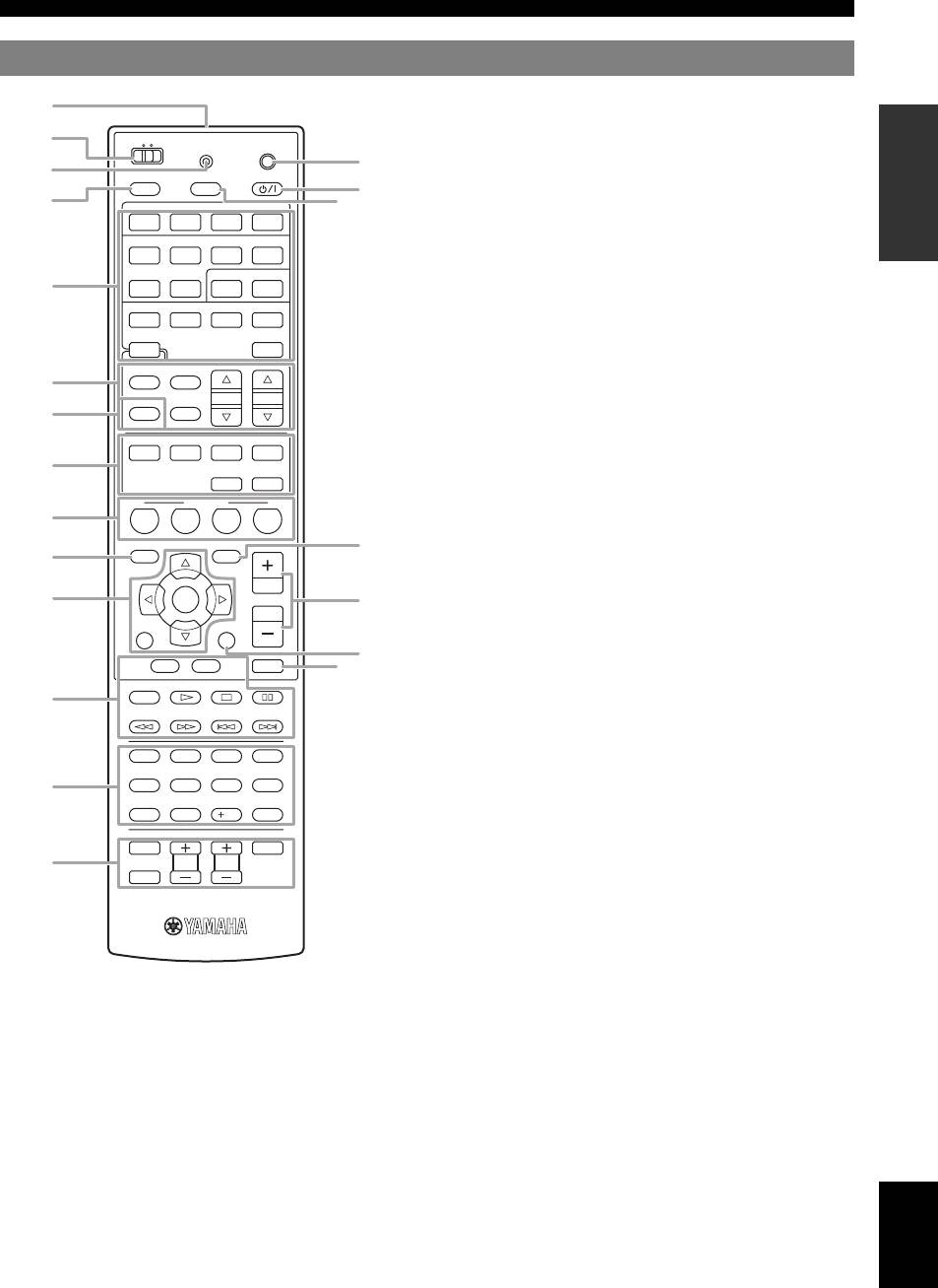
Remote control
INTRODUCTION
MAIN
ZONE2
TRANSMIT
CODE SET
POWER
POWER
SOURCE
SLEEP
HDMI
1234
AV
1234
AUDIO
PREPARATION
1256
V-AUX PHONO
[ A ] DOCK
f Tuner keys
TUNER
MULTI
FM
AM
PRESET
TUNING
INFO
MEMORY
ENHANCER SUR. DECODE
MOVIE
MUSIC
STEREO
g INFO
OPERATION
STRAIGHT
PURE DIRECT
Changes information on the front panel display, such as input
BASIC
source and sound field program name (see page 26).
SCENE
h Sound selection keys
BD
DVD
TV
CD
RADIO
Selects sound field programs (see page 27).
OPTIONSETUP
i SCENE
Switch between linked sets of input sources and sound field
programs (see page 24).
ENTER
VOLUME
j SETUP
RETURN
DISPLAY
Displays the SETUP menu (see page 47).
OPERATION
ADVANCED
k Cursors k / n / l / h/ENTER/RETURN
TOP
MENU
MENU
MUTE
REC
1234
INFORMATION APPENDIX
7856
l External component operation keys
ADDITIONAL
Operate recording, playback etc. of external components
90
10
ENT
(see page 55).
TV
m Numeric keys
INPUT
POWER
Enter numbers.
TV VOL
TV CH
MUTE
n TV control keys
Enable operations of a monitor such as a TV and a projector.
o CODE SET
Sets remote control codes for external component operations
(see page 55).
a Remote control signal transmitter
p POWER
Transmits infrared signals.
Switches this unit on and standby.
b MAIN/ZONE2
q SLEEP
Switches the zone to be operated by the remote control between
Switches the sleep timer operations (see page 38).
the Main zone and Zone2 (see page 54).
r OPTION
c TRANSMIT
Displays the OPTION menu (see page 39).
Lights up when a signal is output from the remote control.
s VOLUME +/–
d SOURCE POWER
Adjust the volume of this unit (see page 24).
Switches an external component on and off.
t DISPLAY
Changes the operation mode of the iPod connected to the
e Input selection keys
Yamaha iPod universal dock (see page 35).
HDMI 1-4
Select HDMI inputs 1 through 4.
English
u MUTE
AV 1-6
Select AV inputs 1 through 6.
Turns the mute function of the sound output on and off
AUDIO 1/2
Select AUDIO inputs 1 and 2.
(see page 25).
V-AUX
Selects the V-AUX jack on the front panel of this
unit.
7 En
a
PHONO
Selects a component such as a turntable that is
connected to the PHONO jack on the rear panel
as an input source.
b
[A]
To control external components using the
o
lExternal component operation
c
keys separately from operations of this unit
p
(see page 55).
d
q
DOCK
Selects a Yamaha iPod universal dock/Bluetooth
wireless audio receiver connected to the DOCK
jack.
TUNER
Selects the FM/AM tuner.
e
MULTI
Selects a signal input from the MULTI CH
INPUT jack on the rear panel as an input source.
FM
Select the FM band or AM band.
AM
f
MEMORY
Presets radio stations.
PRESET k / n
Select a preset station.
g
TUNING k / n
Change tuning frequencies.
h
i
r
j
k
s
t
u
Cursors k / n / l / h
Select menu items displayed on the
front panel display or on a video
l
monitor, or change settings.
ENTER
Confirms a selected item.
RETURN
Returns to the previous screen or
ends the menu display.
m
n
Quick start guide
When you use this product for the first time, perform the steps below. See the related pages for details of operations and
settings.
Step 1: Prepare items for setup
Step 2: Set up your speakers
Prepare speakers, DVD player, cables, and other items
Place your speakers in the room and connect them to this
necessary for setup.
unit.
For example, prepare the following items for setting up a
• Placing speakers ☞P. 1 0
7.1-channel sound system.
• Connecting speakers ☞P. 1 1
Front right speaker
y
Video monitor
Subwoofer
• This unit has a YPAO (Yamaha Parametric Room Acoustic Optimizer)
that automatically optimizes this unit based on room acoustic
Surround right speaker
Front left speaker
characteristics (audio characteristics of the speakers, speaker positions,
and room acoustics, etc.).
You can enjoy good balanced sound without special knowledge by using
the YPAO technology (see page 21).
Step 3: Connect your components
Connect your TV, DVD player, or other components.
• Connecting a video monitor ☞P. 1 5
Center speaker
• Connecting other components ☞P. 1 6
Surround back right
Components
• Connecting a multi-format player or an
speaker
(such as DVD player)
external decoder ☞P. 1 8
Surround back left
• Connecting an external amplifier ☞P. 1 8
Surround left speaker
speaker
• Connecting a Yamaha iPod universal
dock or Bluetooth wireless audio receiver ☞P. 1 9
Requirements qty.
• Connecting the FM and AM antennas ☞P. 2 0
Speakers Front speaker 2
Center speaker 1
Step 4: Turn on the power
Surround speaker 2
Connect the power cable and turn on this unit.
Surround back speaker 2
• Connecting the power cable ☞P. 2 0
Active subwoofer 1
• Turning this unit on and off ☞P. 2 0
Speaker cable 5
Subwoofer cable 1
Step 5: Select the input source and start
playback
Reproduction component such as DVD player 1
Video monitor such as TV 1
Select the component connected in the step 3 as an input
source and start playback.
Video cable or HDMI cable 2
• Basic procedure ☞P. 2 4
Audio cable 2
• Selecting sound field programs ☞P. 2 7
y
• Prepare at least two (front) speakers. Speakers other than front speakers
y
may be used in the following order of preference:
• This unit supports the SCENE function that changes the input source and
1 Two surround speakers
sound field program at one time. Four SCENE are preset for different
2 One center speaker
purposes for Blu-ray disc, DVD and CD. You can select from a SCENE
3 One or two surround back speakers
from those just by pressing a remote control key. See page 24 for details.
• If your video monitor is a CRT, we recommend that you use magnetically
shielded speakers.
• An audio cable is not required when you use an HDMI cable.
8 En


