Yamaha RX-V765 Black: ADVANCED OPERATION
ADVANCED OPERATION: Yamaha RX-V765 Black

ADVANCED OPERATION
Setting the option menu for each input source (OPTION menu)
INTRODUCTION
This unit has the OPTION menu of frequently used menu items for input sources compatible with this unit. The
procedure for setting the OPTION menu items is described below.
1 Select an input source using the RINPUT
OPTION menu items
selector (or eInput selection keys).
The following menu items are provided for each input
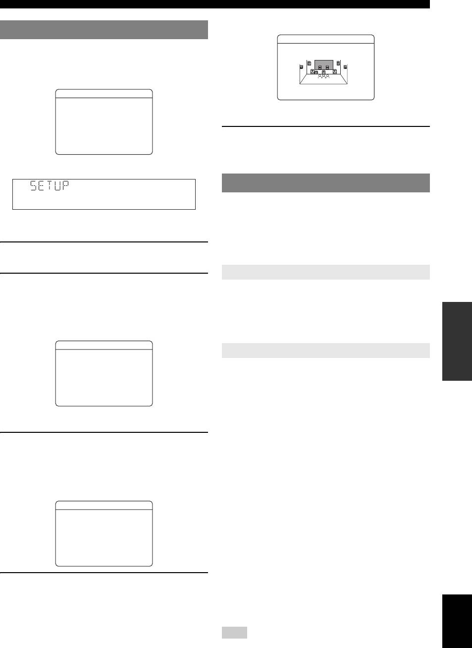
2 Press rOPTION on the remote control.
source.
The OPTION menu appears. The displayed OPTION
PREPARATION
Input
menu items differ depending on the input source. For
Menu item
Source
details, see next section.
HDMI1-4 Volume
Decoder
Extended
Signal Info
Trim
Mode
Surround
HDMI1OPTION
.VolumeTrim
AV1-4 Volume
Decoder
Extended
Signal Info
DecoderMode
ExtendedSurround
Trim
Mode
Surround
SignalInfo
AV5-6 Volume
[
Trim
OPERATION
[]/[]:Up/Down
[
[ENTER]:Select
BASIC
AUDIO1-2 Volume
Trim
3 Select the desired menu item using
kCursor k / n, and press kENTER.
V-AUX Volume
Trim
Parameters of the selected menu item are displayed.
PHONO Volume
4 Change the setting of the selected menu item
Trim
OPERATION
ADVANCED
(or enable a function) using kCursor k / n /
iPod
Vo l u m e
Shuffle Repeat
l / h and kENTER.
(DOCK)
Trim
Details of the selected menu item are displayed.
Parameters you can set differ depending on the menu
Bluetooth
Vo l u m e
Connect/
Pairing
(DOCK)
Trim
Disconnect
items.
TUNER Volume
FM Mode Auto
Clear
5 To close the OPTION menu, press
Trim
Preset
Preset
INFORMATION APPENDIX
rOPTION.
ADDITIONAL
PTY Seek EON
You can also use kRETURN to return to the
previous screen or close the OPTION menu.
MULTI
Vo l u m e
Video Out
CH
Trim
y
• If kCursor or other keys do not work after closing the OPTION
menu, select the input source again using the eInput
Below is a detailed explanation of the menu items in this
selection keys.
table.
y
• The default settings are marked with “*.”
■ Volume Trim
Input source: All
Adjustable range: -6.0 dB to 0.0 dB* to +6.0 dB
(in 0.5 dB steps)
Reduces any change in volume when switching input
sources by correcting volume differences between input
sources.
You can set this parameter for each input source.
English
39 En
Setting the option menu for each input source (OPTION menu)
■ Decoder Mode
■ Signal Info
Input source: HDMI1-4, AV1-4
Input source: HDMI1-4, AV1-4
Choices: Auto*/DTS
Displays information on audio and video signals on the
Selects DTS digital audio signals for reproduction.
video monitor and front panel display. You can change
items to be displayed using kCursor k / n.
Auto Automatically selects audio input signals.
DTS Selects DTS signals only. Other input signals
Signal Info parameters
are not reproduced.
■ Audio information
■ Extended Surround
Input source: HDMI1-4, AV1-4
Information Description
Choices: Auto*/PLIIx Movie/PLIIx Music/EX/ES/
Off
Format
Format of digital audio signals.
Selects whether to reproduce multi-channel input signals
Channel
The number of input signal channels (front/
in 6.1- or 7.1-channel when surround back speakers are
surround/LFE).
used.
For example, if input signal channels are 3
front channels, 2 surrounds and LFE, “3/2/
Auto Automatically selects the most suitable
0.1” is displayed.
decoder according to whether a flag for
If a channel that cannot be expressed as the
reproducing surround back channel is present,
above, a total number of channels such as
and reproduces the signals in 6.1- or 7.1-
“5.1ch” may be displayed.
channel.
PLIIx
Always reproduces signals in 6.1- or 7.1-
Sampling
The sampling frequency of digital input
Movie
channel using the PLIIx Movie decoder
signal.
whether or not surround back channel signals
Bitrate
The bit rate of input signal per second.
are contained. You can select this parameter
when two surround back speakers are
Notes
connected.
• “No Signal” is displayed when no signals are input and “---” is displayed
PLIIx
Always reproduces signals in 6.1- or 7.1-
when signals that this unit cannot recognize are input.
Music
channel using the PLIIx Music decoder
• The bit rate may vary during playback.
whether or not surround back channel signals
■ Video information
are contained. You can select this parameter
when one or two surround back speakers are
Information Description
connected.
In
Format and resolution of video input signal.
EX/ES Automatically selects the most suitable
decoder for input signals whether or not the
Out
Format and resolution of video output signal.
flag for reproducing surround back channel is
Message
Error messages about HDMI signals and
present, and always reproduces signals in 6.1-
HDMI components. See the following for
channel.
details of the error messages.
Off Always reproduces signals in 5.1-channel
when 5.1-channel sound is input, whether or
HDMI error message
not the flag for reproducing surround back
(appears only when an error has occurred)
channel is present.
HDCP Error
HDCP authentication failed.
Device Over
The number of HDMI components connected is
over the limit.
Out of Res.
The connected monitor is not compatible with
the video input signal.
40 En

Setting the option menu for each input source (OPTION menu)
■ FM Mode
Outputting a video signal input from
Input source: TUNER
Choices: Stereo*/Mono
another input source during
Sets FM broadcasting receiving mode.
INTRODUCTION
reproducing a multi-channel audio
Stereo Receives in stereo mode.
signal
Mono Receives in monaural mode. You can get a
better reception in monaural mode.
When “MULTI CH” is selected as the input source, a
video signal input from another terminal can be output to
■ Auto Preset
the video monitor. For example, even if an audio and
Input source: TUNER
video component such as a DVD player that does not
Automatically detects radio stations in the FM frequency
support a multi-channel digital audio output, the video
PREPARATION
band and registers them as preset stations (see page 31).
signal can be output to the video monitor while
reproducing a multi-channel analog audio signal.
■
Clear Preset
Input source: TUNER
1 Rotate the RINPUT selector (or press
Clears the preset stations (see page 32).
eMULTI) to change the input source to
■
PTY Seek
“MULTI CH.”
Input source: TUNER
Searches a station that is broadcasting a program under the
2 Press rOPTION on the remote control.
OPERATION
desired category from the preset stations while using the
The OPTION menu appears.
BASIC
Radio Data System (see page 33).
3 Press kCursor k / n to display “Video Out,”
■
EON
and press kENTER.
Input source: TUNER
The following screen appears.
Enables you to receive the EON (enhanced other network)
data service of the Radio Data System (see page 33).
MULTI CHOPTION
Video Out;;;;Off
■
Shuffle
OPERATION
ADVANCED
Input source: iPod (DOCK)
Choices: Off*/Songs/Albums
Changes the shuffle playback style (see page 36).
[]/[]:Video
[
[
[Return]:Return
■
Repeat
Input source: iPod (DOCK)
4 Press kCursor l / h to select a video input
Choices: Off*/One/All
jack to which a component to be used as a
INFORMATION APPENDIX
Changes the repeat playback style (see page 36).
ADDITIONAL
video input source is connected.
■
Connect / Disconnect
– AV1-2 (COMPONENT VIDEO jacks)
Input source: Bluetooth (DOCK)
– AV3-6 (VIDEO jack)
Switches communication with a Bluetooth component on
– V-AUX (VIDEO jack)
and off (see page 37).
– Off (no video input)
■
Pairing
5 To end the setting, press rOPTION.
Input source: Bluetooth (DOCK)
Performs pairing of this unit and a Bluetooth component
(see page 37).
■
Video Out
Input source: MULTI CH
Choices: AV1 to 6/V-AUX/Off*
When the multi-channel input is selected, outputs a signal
input from another terminal to the video monitor. See
“Outputting a video signal input from another input source
during reproducing a multi-channel audio signal” on this
page.
English
41 En
Editing surround decoders/sound field programs
6 To end the edit, press jSETUP.
Setting sound field parameters
To initialize the parameters of the selected sound field
Although the sound field programs would satisfy you as
program, kCursor n repeatedly to select “Initialize”
they are with the default parameters, you can arrange
and then press, kCursor h. When the confirmation
sound effect or decoders suitable for acoustical conditions
screen appears on the monitor, press kCursor h to
of sources or rooms by setting the parameters (sound field
confirm the initialization or kCursor l to cancel it.
elements).
y
• You can protect the sound field against the changes of parameters the
sound filed parameters when “Memory Guard” of the SETUP menu is set
Sound field parameters
to “On” (see page 52). To change the parameters, set it to “Off.”
y
1 Turn on the video monitor connected to this
• The default settings are marked with “*.”
unit.
CINEMA DSP basic parameters
2 Press jSETUP on the remote control.
SUR.
The SETUP menu appears on the monitor.
Choices: PLIIx Movie*/Neo:6 Cinema
Selects a surround decoder to be used with a sound field
3 Press kCursor k / n to select “DSP
program in the MOVIE category.
Parameter” and press kENTER.
PLIIx Movie: Selects the Dolby Pro Logic IIx (Movie)
The screen changes as follows.
decoder.
Sound field program
Neo:6 Cinema: Selects the Neo:6 (Cinema) decoder.
MOVIE1/2
Page number
Note
Cursor
.Sci-Fi
• Surround decoders cannot be changed when used with the following
SUR.;;;;PLI
I
Movie
MOVIE sound field programs.
3DDSP;;;;;;;;;ON
DSPLevel;;;;;0dB
– Mono Movie
P.Init.Dly;;;16ms
– Sports
P.RoomSize;;;1.0
S.Init.DLY;;;;2ms
– Action Game
– Roleplaying Game
[
p
[]/[]:Select
3D DSP
Sound field parameters
Set values
Choices: On*/Off
When CINEMA DSP 3D is enabled, sets whether to use
4 Press kCursor k / n to move “→” to the
sound field programs in CINEMA DSP 3D mode.
sound field program and press kCursor
Note
l / h to select the sound field program.
• When the presence speakers are not used, the 3D DSP parameters are not
displayed.
5 Press kCursor k / n to select the parameter
DSP Level
that you want to change, and press kCursor
Adjustable range: -6 dB to 0 dB* to +3 dB
l / h to change the parameter.
Fine adjusts an effect level (level of the sound field effect
An asterisk (*) appears on the left of the sound field
to be added). You can adjust the level of the sound field
parameter name displayed on the monitor when you
effect while checking sound levels. Adjust “DSP Level” as
change the parameter from its default setting. For
follows.
details on functions and adjustable ranges of the
sound field parameters, see “Sound field parameters”
• The effect sound is too soft.
on this page.
• There is no difference in effects between the sound field
programs.
y
• Repeat steps 4 and 5 to change other sound field program
→Increase the effect level.
parameters.
• A complete list of the parameters of some sound field programs
• The sound is dull.
may exceed one page. In this case, press kCursor k / n to
• The sound field effect is added too much.
scroll through pages.
→Reduce the effect level.
42 En
Editing surround decoders/sound field programs
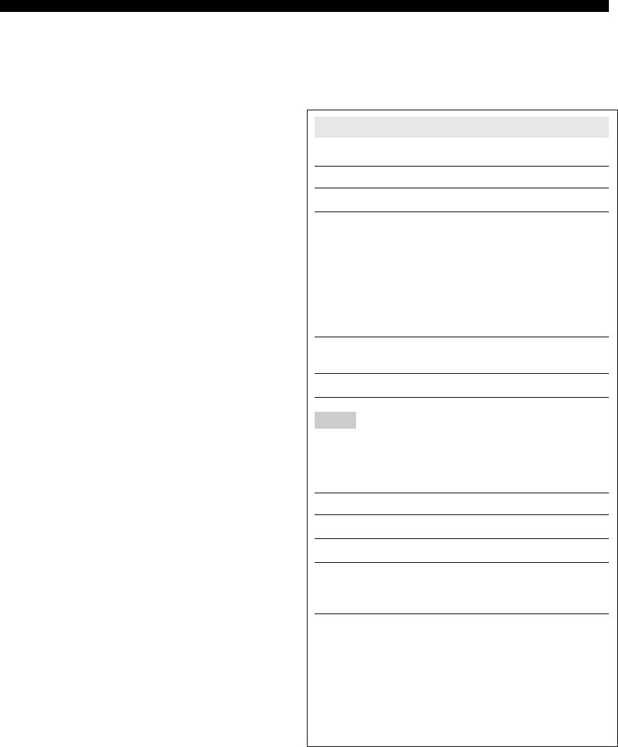
Dialog Lift
Adjust attenuation characteristics of early-reflected sound.
Choices: 0* to 5
You can create a lively sound field (with a high
Adjusts the vertical position of center sound such as
reverberant sound level) as you increase the value, and a
dialogues when presence speakers are used. Increasing
dead sound field (with a low reverberant sound level) as
INTRODUCTION
this parameter raises the position.
you decrease the value. Creating either a lively sound field
or a dead sound field in an actual music hall is determined
by the acoustic absorption characteristics of reflection
surfaces. A dead sound field is created when the
attenuation time is short while a lively sound field is
The ideal dialog
created when the attenuation time is long.
position
Original source sound
PREPARATION
Early-reflected
sound
If the dialog seems to come out from a lower position than
the video monitor screen, increase this parameter.
Level
Level
Time
Time
Delay
Delay
Sound source
OPERATION
Move up to the ideal
BASIC
dialog position
Reflecting
surface
“0” (default) corresponds to the lowest position and “5” to
the highest position.
Small = 1ms Large = 99ms
Notes
y
• “Dialog Lift” is displayed only when the presence speakers are available.
• We recommend that you adjust the size of corresponding sound field
OPERATION
ADVANCED
• You cannot move the dialog position lower than the default setting.
when you adjust the delay time.
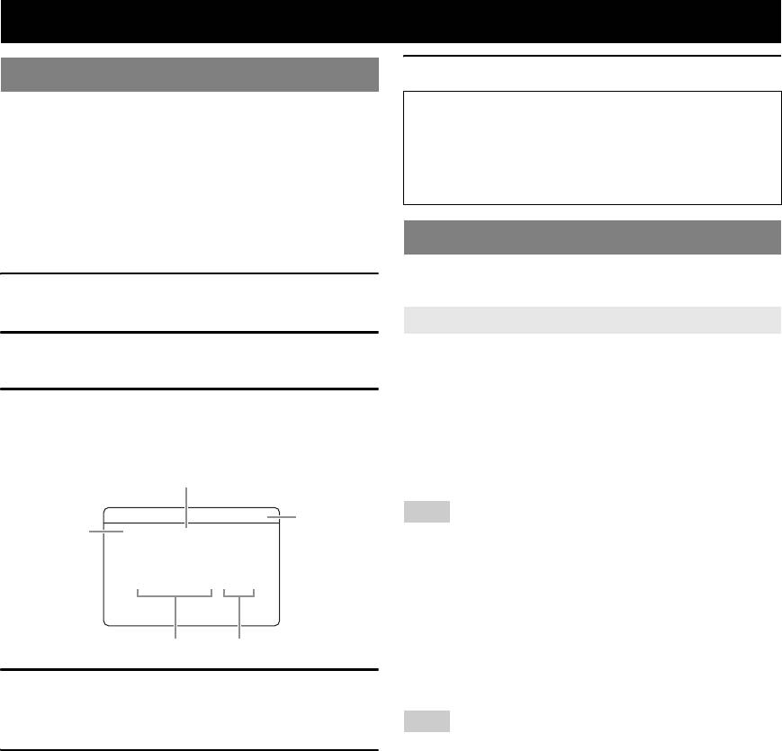
Sound field parameters for the advanced
■ Parameters for specifying room size
configurations
Parameter Adjustable range
y
• Some sound field programs have parameters for adjusting specific sound
Room Size
fields. The following letters are displayed next to the names of those
P.Room Size
parameters.
0.1 to 2.0
S.Room Size
– P (presence sound field)
INFORMATION APPENDIX
ADDITIONAL
– S (surround sound field)
SB Room Size
– SB (surround back sound field)
Produce different senses of sound expansion according to
■ Parameters for adjusting early-reflected
room sizes specified. In a large size room such as a music
sound
hall, the duration from when reflected sound is heard until
Parameter Adjustable range
when the next reflected sound is heard is long. Thus,
different senses of sound expansion can be created by
Init.Dly
1 to 99ms
changing the duration. 1.0 is the original room size. When
P.Init.Dly
1 to 99ms
this parameter is set to 2.0, each side of the room is
S.Init.Dly
1 to 49ms
defined as twice larger than the original room size.
SB Init.Dly
1 to 49ms
English
43 En
Editing surround decoders/sound field programs
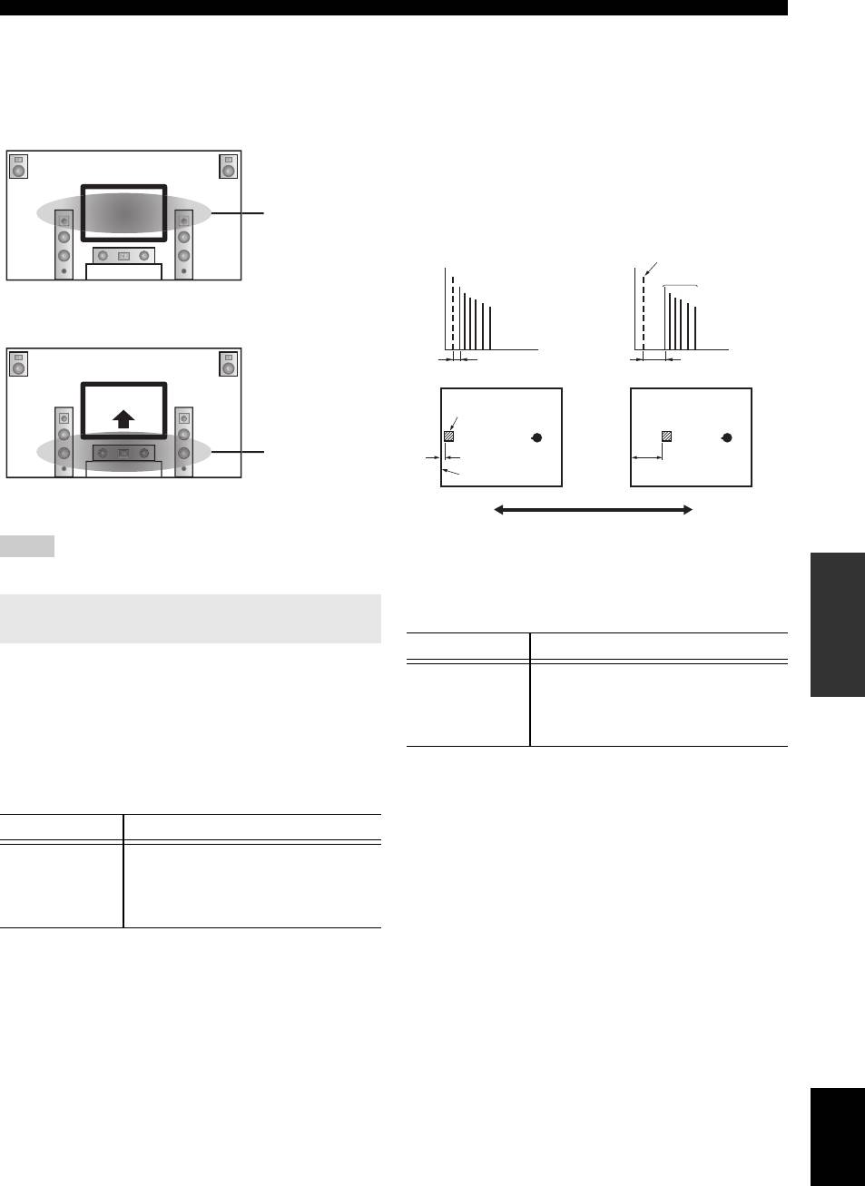
Rev.Time parameter adjusts the attenuation time of the
Source sound
rear reverberant sound based on the time that about 1kHz
reverberant sound takes for 60dB of attenuation.
Early reflections
Reverberant sound attenuates faster as you decrease the
value. Rev.Time adjustment allows you to create a natural
Level
Level
reverberant sound, by setting the attenuation time longer
Time
Time
for a sound source or room with less echo, or shorter for a
sound source or room with more echo.
Sound source
Rear
Source sound
reverberation
Rear reverberation
Early reflections
60dB 60dB
Time Time
Small = 0.1 Large = 2.0
Rev.Time Rev.Time
Short
Long
■ Parameters for defining attenuation
reverberation
reverberation
characteristics of early-reflected sound
Parameter Adjustable range
Sound source
Liveness
0 to 10
S.Liveness
0 to 10
SB Liveness
0 to 10
Small = 1.0s Large = 5.0s
Rev.Delay parameter adjusts the time difference between
Adjust the attenuation of reflected sound. You can create a
the beginning of the direct sound and the beginning of the
lively sound field (with a high reverberant sound level) as
reverberation sound. The larger the value, the later the
you increase the value, and a dead sound field (with a low
reverberation sound begins. Increasing the value of
reverberant sound level) as you decrease the value.
Rev.Delay allows you to create a reverberant sound in a
Creating either a lively sound field or a dead sound field in
wider area for the same Rev.Time.
an actual music hall is determined by the acoustic
absorption characteristics of reflection surfaces. A dead
Source sound
sound field is created when the attenuation time is short
while a lively sound field is created when the attenuation
Level
time is long.
(dB)
Source sound
Live
60dB
Dead
Reverberation
Level
Level
Time
Time
Time
Rev.Delay Rev.Time
Small reflected
Large reflected
sound
sound
Small = 0 Large = 10
■ Parameters for adjusting reverberant sound
Parameter Adjustable range
Rev.Time
1.0 to 5.0s
Rev.Delay
0 to 250ms
Rev.Level
0 to 100%
44 En

Editing surround decoders/sound field programs
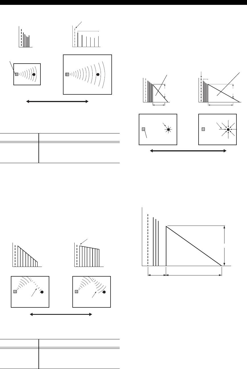
Rev.Level parameter adjusts the reverberation sound level.
Decoder parameters
Increasing the value of Rev.Level makes the reverbration
sound level higher, which allows you to create more echo.
You can customize decoder effects by setting the
following parameters. For kinds of decoders, see page 29.
INTRODUCTION
Source sound
When PLIIx Music/PLII Music is selected
Level
Panorama
Rear reverberation
(dB)
Choices: Off*/On
Rev.Level
Adjusts the soundscape of the front sound field. A small
value increases the soundscape and a large value narrows
it (makes the center more dominant).
PREPARATION
Dimension
Adjustable range: -3 to STD* to +3
Time
Adjusts the difference in level between the front sound
field and the surround sound field. You can adjust the
Parameters only usable in certain sound
difference in level created by the software being played
field programs
back to obtain the preferred sound balance. The surround
sound gets stronger as you make the value more negative
2ch Stereo only
and the front sound gets stronger as you make the value
OPERATION
Direct
more positive.
BASIC
Choices: Auto*/Off
Center Width
Automatically bypasses the DSP circuit and tone control
Adjustable range: 0 to 3* to 7
circuit when an analog sound source is selected as the
Spreads the center sound toward left and right according
input source. This creates a higher quality sound.
to your preference. Set this parameter to 0 for outputting
Auto Outputs sound by bypassing the DSP circuit and
the center sound from the center speaker only, or to 7 for
tone control circuit when the “Bass” and “Treble”
outputting it from the front left/right speaker.
OPERATION
ADVANCED
tone controls are both set to 0 dB.
When Neo:6 Music is selected
Off Does not bypass the circuits.
C.Image
y
• See page 49 for equalizers that can be used with this unit.
Adjustable range: 0.0 to 0.3* to 1.0
Adjusts the front left and right channel output relative to
7ch Stereo only
the center channel to make the center channel more or less
CT Level/SL Level/SR Level/
dominant as necessary.
INFORMATION APPENDIX
SB Level/PL Level/PR Level
ADDITIONAL
Adjustable range: 0 to 100%
Adjusts the volume ofthe center (CT), surround L (SL),
surround R (SR), surround back (SB), presence L (PL)
and presence R (PR) channels in the 7ch Stereo program.
The available parameters differ depending on the setting
of the speakers.
Straight Enhancer/7ch Enhancer only
Effect Level
Choices: High*/Low
Adjusts the Compressed Music Enhancer effect level. To
reduce the effect, set this parameter to “Low.”
English
45 En

Changing various settings of this unit (SETUP menu)
You can change various settings of this unit using the SETUP menu. See “Basic operation of the SETUP menu” on the
next page, and other respective pages to change the settings.
■ List of SETUP menu items
Menu/Submenu Function Page
Speaker Setup Sets items for speakers.
47
1 Auto Setup (YPAO) Automatically adjusts output characteristics of speakers.
47
2 Manual Setup Manually adjusts output characteristics of speakers.
47
A)Config Sets speaker configurations, such as connection status of speaker and a size of the
47
connected speaker (sound reproduction capacity), suitable for the listening
environment.
B)Level Separately adjusts volume of each speaker.
49
C)Distance Adjusts timing at which each speaker outputs sound based on distances between
49
speakers and the listening position.
D)Equalizer Selects an equalizer that adjusts speaker output characteristics.
49
E)Test Tone Generates test tones.
49
Sound Setup Sets various items for sound outputs.
49
1 Dynamic Range Adjusts dynamic ranges of speakers and headphones.
49
2 Lipsync Adjusts delay in output timing between video signals and audio signals.
50
HDMI Auto Sets on or off of automatic adjustments for delay between output timing between
50
video signals input from the HDMI jack and audio signals.
Auto Delay Fine adjusts a delay time of HDMI Auto.
50
Manual Delay Manually fine adjusts the delay of audio and video output.
50
Function Setup Sets various items for HDMI and display.
50
1 HDMI Sets various items for input sources.
50
Control Selects on or off of HDMI control functions.
50
Standby Through Selects on or off of output of HDMI signals input from the HDMI 1-4 jacks to the
50
HDMI OUT jack when this unit is on standby.
Audio Output Selects this unit or a component connected to this unit via the HDMI OUT jack of
50
this unit for reproducing sound signals input from the HDMI 1-4 jacks.
Resolution Sets resolution of the HDMI output that is converted from analogy video input
50
signals.
Aspect Sets an aspect ratio of images reproduced by HDMI signals converted from analog
51
video input signals.
2 Display Sets items for a monitor or the front panel display.
51
Dimmer Sets brightness of the front panel display.
51
FL Scroll Selects the way to display characters on the front panel display.
51
OSD Shift Adjusts top and bottom positions of the OSD (on-screen display) menus.
51
3 Volume Sets items for volumes.
51
Adaptive DRC Adjusts the dynamic range (difference between the maximum volume and the
51
minimum volume) in conjunction with the volume level.
Max Volume Sets the maximum volume level so that the volume will not be accidentally
51
increased.
Init. Volume Sets the volume at the time this unit is turned on.
51
4 Input Rename Changes input source names to be displayed on a video monitor or the front panel
52
display.
5 Zone2 Sets the maximum volume level and initial volume level of Zone2.
52
Max Volume Sets the maximum volume level so that the volume will not be accidentally
52
increased.
Init. Volume Sets the volume at the time this unit is turned on.
52
DSP Parameter Sets parameters for the sound field programs.
52
Memory Guard Protects some settings against accidental alteration.
52
46 En
Changing various settings of this unit (SETUP menu)
Example: A)Config
Basic operation of the SETUP menu
A)Config
The SETUP menu screen appears on both video display
Center SP
INTRODUCTION
(OSD) and front panel display.
Video display (OSD)
SetupMenu
None >Small Large
.;SpeakerSetup
y
;SoundSetup
;FunctionSetup
• You can change other items by repeating step 4.
;DSPParameter
;MemoryGuard
5 To finish setting, press jSETUP.
[
PREPARATION
[]/[]:Up/Down
[
[ENTER]:Enter
y
• If kCursor or other keys do not work after exiting the SETUP menu,
Front panel display
select the input source again using eInput selection keys.
Speaker Setup
;SpeakerSetup
You can set various items for speakers. Two kinds of
adjustments are available. One is “1 Auto Setup (YPAO)”
In this section, procedures of setting menus displayed on
for automatic adjustment and another is “2 Manual Setup”
the video monitor are described.
OPERATION
for manual adjustment.
BASIC
1 Press jSETUP on the remote control.
y
• The default settings are marked with “*.”
The SETUP menu screen appears.
1 Auto Setup
2 Select a menu using kCursor k / n, and
Automatically adjusts output characteristics of speakers to
press kENTER.
obtain optimum balance for the output sound based on
Items of the selected menu are displayed. For
positions and performances of the speakers and acoustic
OPERATION
ADVANCED
example, the following screen appears when you
characteristics or the room, which are automatically
select “Function Setup.”
measured. For details on operations, see page 21.
;FunctionSetup
2Manual Setup
. 1HDMI
2Display
3Volume
Adjusts output characteristics of speakers based on
4InputRename
5Zone2
manually set parameters.
After Auto Setup (YPAO) is performed, you can check
[
INFORMATION APPENDIX
[]/[]:Up/Down
[
ADDITIONAL
[ENTER]:Enter
automatically adjusted parameters in the Manual Setup
menu. Fine adjust the parameters for your preference if
y
• You can return to the previous screen by pressing kRETURN.
necessary.
3 To display submenus, select a menu that you
■
A)Config
Sets speaker configurations, such as connection status of
want to set using kCursor k / n, and press
speaker and a size of the connected speaker (sound
kENTER.
reproduction capacity), suitable for the listening
For example, the following screen appears when you
environment.
select “2 Display.”
y
2Display
• The speaker configuration includes items for defining a speaker size:
Large or Small. Large and Small refer to speakers with woofer diameters
. Dimmer;;;;;;;;;;;;0
16 cm or larger and smaller than 16 cm, respectively.
FLScroll;;Continue
OSDShift;;;;;;;;;0
Extra SP Assign
Choices: Zone2*/Presence/None
[
[]/[]:Up/Down
[
Selects the application for EXTRA SP jacks.
[]/[]:Adjust
[
[
Zone2 Assigns the EXTRA SP jacks for the speakers
4 Select an item using kCursor k / n, and
in the second zone.
change the setting of the item using
Presence Assigns the EXTRA SP jacks for the
English
kCursor l / h.
Presence speaker.
Some items in the Manual Setup menu of Speaker
None Disables the EXTRA SP jacks.
Setup take up a full screen. To display other items in
Note
the Manual Setup menu, press kCursor k / n.
•
When setting “Extra SP Assign” to “Zone2” or “Presence,” the surround back
channel signals for main output is separately output from other channels.
47 En

Changing various settings of this unit (SETUP menu)
LFE/Bass Out
Center SP
Choices: SWFR/Front/Both*
Choices: None/Small*/Large
Selects speaker(s) for outputting low-frequency
Sets the size of center speaker.
components of the LFE (low-frequency effect sound)
None Select this when no center speaker is
channel or other channels. The output status is as follows.
connected. Center channel signals are spread
to front left and right speakers.
LFE channel signals
Small Select this when a small center speaker is
Front
Other
connected. Low-frequency components of
Parameter Subwoofer
speakers
speakers
center channel are output from a subwoofer.
If a subwoofer is not connected they are
Both Output Not output Not output
output from front speakers.
SWFR Output Not output Not output
Large Select this when a large center speaker is
Front Not output Output Not output
connected.
Sur. L/R SP
Low-frequency components of other channel signals
Choices: None/Small*/Large
Front
Other
Parameter Subwoofer
Sets sizes of left and right surround speakers.
speakers
speakers
None Select this when no surround speakers are
Both [1] [2] [3]
connected. Surround channel signals are
SWFR [4] [3] [3]
spread to front left and right speakers. “Sur.B
L/R SP” automatically switches to “None”
Front Not output [1] [3]
when this is selected.
Small Select this when small surround speakers are
[1] Outputs low-frequency components of the front left and right
connected. Low-frequency components of
channels and the channel of speaker, the size of which is set to
surround channels are output from a
“Small.”
[2] Outputs low-frequency components of the front left and right
subwoofer. If a subwoofer is not connected
channels.
they are output from front speakers.
[3] Outputs low frequency components when the sizes of speakers
Large Select this when large surround speakers are
are set to “Large.”
connected.
[4] Outputs low-frequency components of the channel of speaker,
y
the size of which is set to “Small.”
• When “None” is selected, the sound field programs automatically enter
the Virtual CINEMA DSP mode.
Front SP
Sur.B L/R SP
Choices: Small/Large*
Choices: None/SMLx1/SMLx2*/LRGx1/LRGx2
Sets the sizes of front left and right speakers.
Sets sizes of left and right surround back speakers.
Small Select this when small speakers are
connected. Low-frequency components of the
None Select this when no surround back speaker
front left and right channels are output from a
are connected. Surround back channel signals
subwoofer.
are output from the surround L/R speakers
Large Select this when large speakers are
and subwoofer. If the subwoofer is disabled,
connected.
they are output from the surround L/R
speakers and front speakers.
Note
SMLx1 Select this when one small surround back
• When “LFE/Bass Out” is set to “Front,” you can only select “Large.” If
speaker is connected.
“LFE/Bass Out” is changed to “Front,” this parameter automatically
switches to “Large” even when it is set to “Small.”
SMLx2 Select this when two small surround back
speakers are connected.
LRGx1 Select this when one large surround back
speaker is connected.
LRGx2 Select this when two large surround back
speakers are connected.
Note
• When “None” is selected, “PLIIx Movie,” “PLIIx Music,” and “PLIIx
Game” cannot be selected.
48 En

Changing various settings of this unit (SETUP menu)
Crossover Freq.
■ D)Equalizer
Choices: 40Hz/60Hz/80Hz*/90Hz/100Hz/110Hz/120Hz/
Adjusts sound quality and tone using a parametric graphic
160Hz/200Hz
equalizer.
Sets the lower limit of the low frequency component
INTRODUCTION
EQ Type Select
output from a speaker with a size set to “Small (SMLx1/
Choices: Auto PEQ/GEQ*/Off
SMLx2).” Sound with a frequency below that limit is
Selects an equalizer type.
output from a subwoofer or front speakers.
Auto PEQ Uses a parametric equalizer selected in
y
• If your subwoofer has a volume control or a crossover frequency control,
“1 Auto Setup.” Characteristics of the
set the volume to half or the crossover frequency at the maximum.
currently used parametric equalizer
(see page 21) are displayed below “Auto
Subwoofer Phase
PEQ.”
PREPARATION
Choices: Normal*/Reverse
If Auto Setup is not executed, this
Sets the phase of your subwoofer if bass sounds are
parameter is not displayed.
lacking or unclear.
GEQ Adjusts tone using a graphic equalizer. To
display the adjustment menu, press
Normal Select this not to change the phase of your
kENTER.
subwoofer.
Off Not use a graphic equalizer.
Reverse Select this to reverse the phase of your
subwoofer.
GEQ
Choices: 63Hz/160Hz/400Hz/1kHz/2.5kHz/
OPERATION
■
B)Level
6.3kHz/16kHz
BASIC
Adjustable range: -10.0dB to +10.0dB (0.5 dB steps)
Adjustable range: -6.0dB to 0dB* to +6.0dB (0.5 dB steps)
Defaults: “FR.L/FR.R/SWFR/PR.L/PR.R” 0dB
Adjusts sound quality of each speaker using a graphic
“CNTR/SUR.L/SUR.R/SBL/SBR” -1.0dB
equalizer. The graphic equalizer of this unit can adjust
Separately adjusts volume of each speaker so that the
signal levels in 7 frequency ranges.
sounds from speakers are at the same volume at the
To adjust the signal level within each range, select the
listening position. Items to be displayed vary depending
desired speaker with kCursor l / h while “→” is
on the number of speakers connected.
displayed next to “Channel,” then the desired frequency
OPERATION
ADVANCED
y
band with kCursor k / n, and adjust the signal level
• When only one surround back speaker is connected, “SB” appears
with kCursor l / h.
instead of “SBL” and “SBR.”
• You can adjust the volume listening to test tones when you set “E)Test
■
E)Test Tone
Tone” to “On” (see page 49).
• If your subwoofer has a volume control or a crossover frequency control,
Choices: Off*/On
set the volume to half or the crossover frequency at the maximum.
Switches test tones on and off. To generate test tones
■ C)Distance
select “On” using kCursor l / h. When “On” is
INFORMATION APPENDIX
Adjusts timing at which each speaker outputs sound so
selected, you can adjust the settings of “2 Manual Setup”
ADDITIONAL
while listening to a test tone.
that sounds from speakers reach the listening position at
the same time. Set the unit (Unit) first and then the
Off Does not generate test tones.
distance of each speaker.
On Generates test tones.
Unit
Sound Setup
Choices: meters (m)*/feet (ft)
You can set various items for sound outputs.
meters (m) Displays the speaker distance in meters.
y
feet (ft) Displays the speaker distance in feet.
• The default settings are marked with “*.”
■ 1 Dynamic Range
Front L
/ Front R / Center / Sur. L /
Choices: Min/Auto/STD/Max*
Sur. R / Sur.B L / Sur.B R / SWFR/
Selects the dynamic range adjustment method for
PRNS L/ PRNS R
reproducing bitstream signals.
Adjustable range: 0.30m to 24.00m (1.0ft to 80.0ft)
Min/Auto (Min) Sets the dynamic range suitable for
Defaults: 3.00m (10.0ft) “Front L/Front R/
low volume or a quiet environment, such as
SWFR/PRNS L/PRNS R”
at night, for bitstream signals except for
2.60m (8.5ft) “Center”
Dolby TrueHD signals.
2.40m (8.0ft) “Sur. L/Sur. R/
(Auto) Adjusts the dynamic range for Dolby
Sur.B L/Sur.B R/PRNS L/PRNS R”
TrueHD signals based on input signal
English
information.
y
• Different items are displayed depending on settings of “A)Config”
STD Sets the standard dynamic range
(see page 47).
recommended for regular home use.
• When only one surround back speaker is connected, “Sur.B” appears
Max Outputs sound without adjusting the
instead of “Sur.B L” and “Sur.B R.”
dynamic range of the input signals.
49 En

Changing various settings of this unit (SETUP menu)
■ 2 Lipsync
■
Standby Through
Adjusts delay between video output and audio output.
Choices: On/Off*
Selects on or off of output of HDMI signals input from the
HDMI Auto
HDMI 1-4 jacks to the HDMI OUT jack when this unit is
Choices: Off*/On
on standby. When this parameter is set to “On” signals
Automatically adjusts output timing of audio and video
input from the HDMI 1-4 jacks can be output to a monitor
signals when a monitor that supports an automatic lip-
component.
sync function is connected to this unit.
This item is not displayed when “Control” is set to “On.”
Off Select this when the connected monitor does
On Outputs the HDMI signals to the HDMI OUT
not support the automatic lip-sync function or
jack.
that function is not to be used. Set the
Off Does not output the HDMI signals to the
correction time in “Manual Delay.”
HDMI OUT jack.
On Select this when the connected monitor
supports the automatic lip-sync function. Fine
y
• To enables pass-through output, any one of the input sources connected
adjust the correction time in “Auto Delay.”
to the HDMI 1-4 jacks must be selected before switching to standby.
• During pass-through output, the HDMI THROUGH indicator on the
Auto Delay
front panel display lights up. While the indicator lights up, it consumes 1
Adjustable range: 0* to 240ms (1 ms steps)
to 3W of power depending on a condition of an HDMI signal passing
through this unit.
Fine adjusts the correction time when “HDMI Auto” is set
to “On.” The actual correction time is displayed under in
■ Audio Output
“Auto Delay” field and an offset time set by the user in
Choices: Amp*/TV/Amp+TV
“offset” field.
Selects this unit or a component connected to this unit via
the HDMI OUT jack of this unit for reproducing sound
Manual Delay
signals input from the HDMI 1-4 jacks.
Adjustable range: 0* to 240ms (1 ms steps)
This item is not displayed when “Control” is set to “On.”
Manually fine adjusts the correction time. Select this when
the connected monitor does not support the automatic lip-
Amp Outputs HDMI sound signals form the
sync function or you set “HDMI Auto” to “Off.”
speakers connected to this unit.
TV Outputs HDMI sound signals from the
Function Setup
speakers of a TV connected to this unit.
Sound output from the speakers connected to
You can set various items for HDMI and display.
this unit is muted.
y
Amp+TV Outputs HDMI sound signals from the
• The default settings are marked with “*.”
speakers connected to this unit and the
1HDMI
speakers of a TV connected to this unit.
You can set items for HDMI.
Note
• When “TV” or “Amp+TV” is selected, signal formats of audio and video
■
Control
signals output from this unit to the monitor vary depending on
Choices: On/Off*
specifications of the monitor.
Selects on or off of HDMI control functions when a
■ Resolution
component that supports the HDMI control functions is
Choices: Through*/576p/720p/1080i/1080p
connected with this unit.
Upscales the resolution of HDMI output that is converted
When this is set to “On,” signals input from the HDMI 1-4
from analog video input signals and output from the
jacks are output to a monitor component even when this
HDMI OUT jack.
unit is on standby.
Notes
On Enables the HDMI control function.
• Resolution of the HDMI output converted from 720p or 1080i video
Off Disables the HDMI control function.
signals cannot be upscaled.
• When a video monitor is connected to this unit via the HDMI jack, this
unit automatically detects a resolution that the monitor supports. An
asterisk (*) appears on the left of the detected resolution.
• If this unit cannot detect the resolution that the monitor supports, set
“MON.CHK” in the ADVANCED SETUP menu to “SKIP”
(see page 58) and try it again.
50 En

Changing various settings of this unit (SETUP menu)
■ Aspect
3Volume
Choices: Thrgh*/16:9/Smart
Sets a horizontal to vertical ratio (aspect ratio) of images
You can change some parameters for volumes.
reproduced by HDMI signals output from the HDMI OUT
INTRODUCTION
■
Adaptive DRC
jack when the HDMI signals are converted from analog
Choices: Auto/Off*
video input signals by a video conversion function.
Adjusts the dynamic range in conjunction with the volume
Thrgh Outputs the video signals without changing
level. This function is useful when you are listening at
the aspect ratio.
lower volumes or at night. When this function is enabled,
16:9 Outputs the video signals that displays 4:3
the dynamic range is adjusted as follows.
images on a 16:9 monitor with black bands
If the volume setting is low:
on the right and left sides of the monitor
the dynamic range is narrow
PREPARATION
screen.
If the volume setting is high:
Smart Outputs the video signals that displays 4:3
the dynamic range is wide
images on a 16:9 monitor by stretching right
and left of images to fit on the monitor
screen.
Auto
Notes
Auto
• You cannot change the aspect ratio of the screen when “Resolution” is set
to “Through.”
Output level
Off Off
Output level
OPERATION
• The setting is not effective for inputs with the aspect ratio other than 4:3.
• You cannot obtain an effect of the aspect ratio when video signals are
BASIC
Input levelInput level
input from the HDMI 1-4 jacks or 720p, 1080i or 1080p signals are input.
Volume: highVolume: low
2Display
Auto Adjusts the dynamic range automatically.
You can change some parameters for a monitor or the
Off Does not adjust the dynamic range
front panel display.
automatically.
■
Dimmer
OPERATION
y
ADVANCED
• The “Adaptive DRC” setting is effective for headphones.
Adjustable range: -4 to 0*
Sets brightness of the front panel display. As the value is
■ Max Volume
lowered, the brightness of the front panel display is
Adjustable range: -30.0dB to +15.0dB/+16.5dB* (5.0 dB
darkened.
steps)
Sets the maximum volume level so that the volume will
Note
not be accidentally increased. For example, you can adjust
• The brightness of display does not become bright in Pure Direct mode
even if the value is increased.
the volume between –80.0 dB and –5.0 dB or mute when
INFORMATION APPENDIX
ADDITIONAL
you set this parameter to “–5.0dB.” The volume increases
■ FL Scroll
to the maximum level when this parameter is set to
Choices: Continue*/Once
+16.5 dB (default).
Selects the way to scroll the screen when a total number of
characters exceed a display area of the front panel display.
■
Init. Volume
Choices: Off*/Mute/-80.0dB to +16.5dB (0.5 dB steps)
Continue Repeatedly displays all characters by
Sets the volume at the time this unit is turned on. When
scrolling.
this parameter is set to “Off,” the volume is set to a level
Once Displays all characters by scrolling once,
that last time this unit is set to standby.
halts scrolling, and then displays first 14
characters.
Note
• If the setting of “Max Volume” is lower than the setting of “Init.
■
OSD Shift
Volume,” the setting of “Max Volume” becomes effective. For example,
Adjustable range: -5 to 0* to +5
when you set “Max Volume” to “–30.0dB” and “Init. Volume” to
“0.0dB,” the volume is automatically set to “–30.0dB” at the next time
Adjusts top and bottom positions of the OSD (on-screen
this unit is turned on.
display) menus. To move up the screen, set this value
larger. To move down the screen, set it smaller.
English
51 En

Changing various settings of this unit (SETUP menu)
4 Input Rename
Note
• If the setting of “Max Volume” is lower than the setting of “Init.
You can change input source names to be displayed on the
Volume,” the setting of “Max Volume” becomes effective. For example,
when you set “Max Volume” to “–30.0dB” and “Init. Volume” to
front panel display.
“0.0dB,” the volume is automatically set to “–30.0dB” at the next time
You can select an input source that you want to change the
this unit is turned on.
name to be displayed using kCursor.
DSP Parameter
Selecting a name to be displayed from templates
Select an input source that you want to change the name,
You can change some parameters for the sound field
and select a name from the following templates using
programs. For details, see page 42.
kCursor.
Memory Guard
– Blu-ray – Satellite
– DVD – VCR
y
– SetTopBox – Tape
• The default settings are marked with “*.”
– Game – MD
– TV – PC
Choices: Off*/On
– DVR – iPod
Protects settings of SETUP menu against accidental
– CD – HD DVD
alteration.
– CD-R – “blank”
Off Does not protect settings.
y
• If you change the display name of an input source to your original one
On Protects the settings of the SETUP menu
and select the input source, the current input source name and the
(except for the Memory Guard setting).
template name are displayed. This is convenient if you want to cancel
name change operation.
Note
Entering an original name
• When this parameter is switched to “On,” “G” appears while the SETUP
menu is displayed on the video monitor.
Select an input source that you want to name, and press
kENTER. You can enter up to 9 characters by selecting
one character at a time with the following keys according
to the following operation.
kCursor l / h For selecting characters that you
want to change
kCursor k / n For selecting characters to be
entered
kENTER For entering the selected characters
The following characters are available for input.
A to Z, 0 to 9, a to z, symbols (#, *, –, +, etc.) and space
5 Zone2
You can set the maximum volume level and initial volume
level of Zone2.
y
• This item is displayed only when “Extra SP Assign” is set to “Zone2.”
■ Max Volume
Adjustable range: -30.0dB to +15.0dB / +16.5dB*
(5.0 dB steps)
Sets the maximum volume level of Zone2 so that the
volume will not be accidentally increased. For example,
you can adjust the volume between –80.0 dB and –5.0 dB
or mute when you set this parameter to “–5.0dB.”
■
Init. Volume
Choices: Off*/Mute/-80.0dB to +16.5dB (0.5 dB steps)
Sets the volume level of Zone2 when the power of Zone2
unit is turned on.
52 En
Using multi-zone configuration
This unit allows you to configure a multi-zone audio system. The Zone2 feature allows you to set this unit to reproduce
separate input sources in the main zone and the second zone (Zone2). You can control this unit from the second zone
INTRODUCTION
using the supplied remote control.
Only analog signal can be sent to Zone2. If you want to output sound from Zone2, connect an external component to
AV5-6 or AUDIO1-2 by analog connection. For example, if you want to output sound from an HDMI DVD player in
Zone2, you must connect the component to this unit by both HDMI and analog connections.
Note
Connecting Zone2
• To avoid unexpected noise, DO NOT USE the Zone2 feature with CDs
PREPARATION
encoded in DTS.
You need the following additional equipment to use the
multi-zone functions of this unit:
Using the internal amplifier of this unit
• An infrared signal receiver in the second zone.
• An infrared signal emitter in the main zone. This emitter
Important safety notice
transmits infrared signals from the remote control to a
The EXTRA SP jacks of this unit should not be
CD player or a DVD player, etc. in the main zone via
connected to a Passive Loudspeaker Selector Box or
the infrared signal receiver in the second zone.
more than one loudspeaker per channel.
• An amplifier and speakers in the second zone.
OPERATION
Connection to a Passive Loudspeaker Selector Box or
BASIC
y
multiple speakers per channel could create an
• Since there are many possible ways to connect and use this unit in a
abnormally low impedance load resulting in amplifier
multi-zone configuration, we recommend that you consult with your
damage. See this owner’s manual for correct usage.
nearest authorized Yamaha dealer or service center about the Zone2
connections that best meet your requirements.
Compliance with minimum speaker impedance
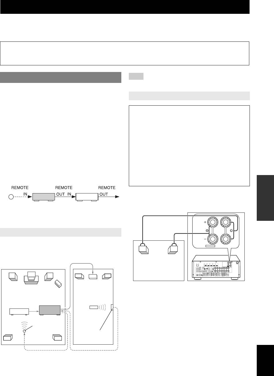
• Some Yamaha models can be directly connected to the REMOTE jacks
information for all channels must be maintained at all
of this unit. These models may not require an infrared signal emitter. Up
times. This information is found on the back panel of
to 6 Yamaha components can be connected as shown below.
this unit.
OPERATION
ADVANCED
Connect the speakers in the second zone to the EXTRA
SP jacks and then set the “Extra SP Assign” to “Zone2”
Infrared signal
This unit Yamaha
(see page 47).
receiver
component
INFORMATION APPENDIX
ADDITIONAL
Using the external amplifier
You can connect the amplifier/receiver in the second zone
EXTRA SP
ZONE2
/
PRESENCE
and other components to this unit as follows.
From the ZONE2 OUT jacks
DOCK
HDMI
OUT
(
HDMI 1 HDMI 2 HDMI 3 HDMI 4
BD/DVD
)
Second zone
VIDEO
PHONO
EXTRA SP
ZONE2
PRESENCE
/
R
COMPONENT
P
FM
ANTENNA MONITOR OUT
GND
AM
COMPONENT
P
R
VIDEO
REMOTE
SPEAKERS
IN
SINGLE
(Zone2)
B
P
GND
Y
VIDEO
UNBAL.
B
P
VIDEO
OUT
Y
TRIGGER OUT
0.1A MAX.
12V
CENTER
FRONT
CENTER
SURROUND
SURROUND BACK/
CENTERSINGLE
BI-AMP
OPTICAL
(
TV
A
V
1
)
COAXIAL
AV 2
COAXIAL
CD
AV 3
(
)
OPTICAL
AV 4
AV 5
AV 6
AV
OUT
AUDIO1
AUDIO2
FRONT
MULTI CH INPUT
SURROUND
SUR.BACK
SUBWOOFER
AUDIO
OUT
ZONE2
OUT
ZONE2
FRONT
SURROUND
PRE OUT
SUR. BACK
12
SUBWOOFER
Amplifier
This unit
Main zone
Second zone
Main zone
(Zone2)
DVD player (etc.)
y
• You can use the speakers connected to the EXTRA SP jacks as the front
Remote control
speaker system of another zone. Set “Extra SP Assign” to “Zone2”
This unit
(see page 47).
• When you use the internal amplifiers for the Zone2 speakers, you can
Infrared signal
adjust the volume level and set the initial volume and maximum volume
emitter
Infrared signal
of the Zone2 speakers (see page 52).
receiver
English
From the REMOTE OUT jack
To the REMOTE IN jack
53 En

Using multi-zone configuration
■ Setting Zone2 to standby
Controlling Zone2
Press CZONE2 ON/OFF to set Zone2 to
You can select and control Zone2 by using the control
standby.
keys on the front panel or on the remote control. The
available operations are as follows:
Controlling Zone2 with the remote control
• Selecting the input source (AV5-6, AUDIO1-2, V-AUX)
■ Turning on Zone2
of Zone2.
• Adjusting the volume of Zone2 (when a Zone2 speaker
Set bMAIN/ZONE2 to the ZONE2 position, and
is connected to the EXTRA SP jack).
press pPOWER.
• Tuning into FM or AM when “TUNER” is selected as
the input source of Zone2 (see page 31).
■ Operating Zone2
• Playing back music stored on your iPod stationed in a
Yamaha iPod universal dock (such as YDS-11 sold
Set bMAIN/ZONE2 to the ZONE2 position, and
separately) connected to the DOCK jack.
press one of the input selection keys to select
• You can play back music stored on a Bluetooth
the desired input source of Zone2.
component via a Bluetooth wireless audio receiver (sold
separately) connected to the DOCK jack (see page 37).
Note
• uMUTE and sVOLUME +/– are available to control Zone2 with
Note
same procedure as mentioned above.
• You must complete each step while the ZONE2 indicator is flashing on
the front panel display. Otherwise, the Zone2 mode is automatically
■ Setting Zone2 to standby
canceled and this unit returns to the normal operation mode. In this case,
repeat the Zone2 selection procedure.
Set bMAIN/ZONE2 to the ZONE2 position, and
press pPOWER, then set ZONE2 to standby.
Controlling Zone2 with the front panel
■ Turning on Zone2
Press CZONE2 ON/OFF to turn on Zone2.
■ Activating the Zone2 operation mode
Press EZONE2 CONTROL to control Zone2.
The ZONE2 indicator flashes on the front panel display
for approximately 10 seconds.
ZONE
Flashes
2
■ Operating Zone2
Rotate the RINPUT selector to select the
desired input source while the ZONE2 indicator
on the front panel display is flashing.
• When AV5-6, AUDIO1-2 or V-AUX is selected, you
can listening to the input source in Zone2.
• Select “TUNER” as the input source to use the TUNER
features in Zone2. For details about the TUNER
operations, see “FM/AM tuning” on page 31.
• Select “DOCK” as the input source to use iPod features
in Zone2. For details about the iPod operations, see
“Using iPod” on page 35.
• Select “DOCK” as the input source to use Bluetooth
component features in Zone2. For details about the
Bluetooth component operations, see “Using Bluetooth
components” on page 37.
54 En

Controlling other components with the remote control
You can control external components for a selected input source with the remote control. The keys available for
controlling external components are as follows:
INTRODUCTION
dSOURCE POWER
Default
Turns on and off an external component.
Input source Category Manufacturer
code
kCursor, ENTER, RETURN
[DOCK] DOCK Yamaha 5011
Operates the menus of external components.
[TUNER] Tuner Yamaha 5007
tDISPLAY
[MULTI CH] — — —
Switches between the screens of external components.
“—” indicates no assignment
lExternal component operation keys
PREPARATION
y
Function as a recording or playback key of an external
• An external component that is controlled by the remote control can be
component, or a menu display key.
automatically selected according to the iSCENE key selection
(see page 25).
mNumeric keys
Function as numeric keys of an external component.
Setting remote control codes
nTV control keys
You can control other components by setting the
INPUT Switches video inputs of TV
appropriate remote control codes. For a complete list of
OPERATION
MUTE Mute audio of TV
available remote control codes, refer to “List of remote
BASIC
TV VOL +/– Controls the volume of TV
control codes” at the end of this manual.
TV CH +/– Switches channels of TV
y
POWER Turns on and off TV
• Each of the steps described in this section should be performed within
one minute. Setting operation is automatically canceled when one minute
y
has passed since the last step. If the operation is cancelled, start again
• You need to set the remote control code first to control external
from the beginning.
components.
• The remote control keys for controlling external components are
1 Press oCODE SET on the remote control
available only when the external components have corresponding control
OPERATION
ADVANCED
keys.
using a pointed object such as the tip of a
ballpoint pen.
The following remote control codes are assigned to input
cTRANSMIT on the remote control blinks twice.
sources as factory default settings. For a complete list of
available remote control codes, refer to “List of remote
2 Press eInput selection keys
control codes” at the end of this manual.
corresponding to the input source whose
■ Default remote control code settings
remote control code you want to register.
INFORMATION APPENDIX
ADDITIONAL
Default
3 Enter a remote control code using
Input source Category Manufacturer
code
mNumeric keys.
[HDMI1] Blu-ray Disc Yamaha 2018
Once the remote control code is registered,
cTRANSMIT on the remote control blinks twice.
[HDMI2] — — —
If it fails, cTRANSMIT blinks six times. Repeat
[HDMI3] — — —
from step 1.
[HDMI4] — — —
[AV1] — — —
[AV2] — — —
[AV3] CD Yamaha 5013
[AV4] — — —
[AV5] — — —
[AV6] — — —
[AUDIO1] — — —
[AUDIO2] — — —
English
[V-AUX] — — —
[PHONO] — — —
[A] — — —
55 En
Controlling other components with the remote control
Programming from other remote controls
The remote control of this unit can receive remote control signals from other remote controls and learn the remote control
operation. If a key on the remote control does not work after being assigned with an external component’s function or if
the remote control code for that function is not provided, use this learning feature to make the function operable with the
remote control.
y
• Each of the steps described in this section should be performed within one minute. Setting operation is automatically canceled when one minute has
passed since the last step. If the operation is cancelled, start again from the beginning.
Programming the remote control of this
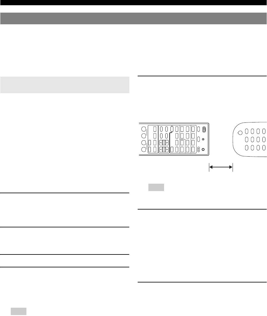
5 Place the remote control about 5 to 10 cm
unit
apart from the remote control of the external
component on a flat surface so that their
You can program the remote control to make functions of
infrared transmitters are aimed at each other.
an external component operable with the following keys.
You can assign functions to these keys for each input
Remote control of external
component
source as with remote control codes.
DVD
POWER
BD
MOVIE
MAIN
INFO
FM
TUNER
V-AU X
1234
1234
SOURCE
dSOURCE POWER
ZONE2
TV
MUSIC
MEMORY
AM
PHONO
SCENE
AV
HDMI
SLEEP
TRANSMIT
lExternal component operation keys
OPTIONSETUP
ENHANCER SUR. DECODE
CD
STRAIGHT
STEREO
PRESET
[ A ] DOCK
1256
AUDI O
RADIO
PURE DIRECT
TUNING
MULTI
POWER
CODE SET
mNumeric keys
y
• The remote control transmits infrared rays. If the remote control of the
external component also uses infrared rays, this remote control can learn
most of its functions. The remote control may not recognize special or
5 to 10 cm
consecutive signals.
• The keys may not operate the assigned functions depending on operating
conditions of this unit.
Note
• If 10 seconds pass after step 4 is performed, an error occurs and
1 Press oCODE SET on the remote control
this unit cannot receive remote control signals. If cTRANSMIT
turns off before you do step 6, repeat from step 4.
using a pointed object such as the tip of a
ballpoint pen.
6 Press the key on the remote control of the
cTRANSMIT on the remote control blinks twice.
external component.
The function assigned to the selected key is also
2 Press eInput selection keys to select the
assigned to the key that you have selected in step 4.
input source whose function you want to
When the function is assigned to the key successfully,
assign to the remote control.
cTRANSMIT on the remote control blinks twice.
If it fails, cTRANSMIT blinks six times. Repeat
3 Enter “9990” using mNumeric keys.
from step 4.
4 Press a key to which you want to assign the
y
• To continue assigning other functions, repeat steps 4 through 6.
function.
cTRANSMIT lights up and this unit enters a wait
7 To end programming, press oCODE SET on
state to receive remote control signals. Do steps 5 and
the remote control using a pointed object
6 within 10 seconds.
such as the tip of a ballpoint pen.
cTRANSMIT on the remote control blinks once.
Note
• If 10 seconds pass after this unit enters the wait state, a timeout
error occurs and cTRANSMIT turns off. If this occurs, repeat
from step 4.
56 En

Controlling other components with the remote control
Clearing the assignment of each key
Resetting all remote control codes
You can clear the assignment of each key.
You can clear all the remote control codes previously set,
INTRODUCTION
and reset all of them to the initial factory settings.
1 Press oCODE SET on the remote control
y
using a pointed object such as the tip of a
• Each of the steps described in this section should be performed within
ballpoint pen.
one minute. Setting operation is automatically canceled when one minute
has passed since the last step. If the operation is cancelled, start again
cTRANSMIT on the remote control blinks twice.
from the beginning.
2 Press eInput selection keys to select the
1 Press oCODE SET on the remote control
input source whose assigned function you
using a pointed object such as a tip of a
PREPARATION
want to reset.
ballpoint pen.
cTRANSMIT on the remote control blinks twice.
3 Enter “9991” using mNumeric keys.
2 Press jSETUP on the remote control.
4 Press the key that you want to reset.
The assignment to that key is cleared. When the
3 Enter “9981” using mNumeric keys.
assignment is cleared successfully, cTRANSMIT
Once the initialization is complete, cTRANSMIT
on the remote control blinks twice.
on the remote control blinks twice. If it fails,
If it fails, cTRANSMIT blinks six times. Repeat
OPERATION
cTRANSMIT blinks six times. Repeat from
from step 1.
step 1.
BASIC
y
• To continue resetting other keys, repeat step 4.
5 To end the reset operation, press oCODE
SET on the remote control using a pointed
object such as the tip of a ballpoint pen.
OPERATION
cTRANSMIT on the remote control blinks once.
ADVANCED
Clearing the assignments of all keys
You can clear the assignments of all the keys in one go.
1 Press oCODE SET on the remote control
using a pointed object such as the tip of a
ballpoint pen.
INFORMATION APPENDIX
ADDITIONAL
cTRANSMIT on the remote control blinks twice.
2 Press eInput selection keys to select the
input source, the function of which is
assigned to the key that you want to reset.
3 Enter “9992” using mNumeric keys.
The assignments of all key are cleared. When the
assignments are cleared successfully,
cTRANSMIT on the remote control blinks twice.
If it fails, cTRANSMIT blinks six times. Repeat
from step 1.
y
• When you initialize the remote control code (see the next section), the
assignments of all the keys are cleared.
English
57 En

Advanced setup
The advanced setup includes more parameters for basic
MON.CHK - XXXX
operation of this unit such as turning a bi-amp connection
Choices: YES*/SKIP
on and off and initializing user settings. This section
Adds upscaling limitation on output signals to a video
describes what those parameters are and how to change
monitor connected to this unit via the HDMI OUT
them.
jack.
1 Set this unit to standby.
INIT-XXXXXXXXX
Choices: DSP PARAM/VIDEO/ALL/CANCEL*
2 Press AMAIN ZONE ON/OFF while
Initializes various settings stored in this unit. You can
pressing and holding PSTRAIGHT on the
select an initialization method from the following.
front panel.
DSP PARAM Resets all parameters of sound field
The ADVANCED SETUP menu appears on the front
programs.
panel display.
VIDEO Resets video conversion settings
(resolution/aspect) in the SETUP
menu and the OSD menus display
position.
ADVANCEDSETUP
ALL Resets this unit to initial factory
settings.
3 Rotate the OPROGRAM selector to select
CANCEL Initialization.
the parameter you want to change.
4 Press PSTRAIGHT a few times to select the
y
• Set values are placed in XXX of the following parameters on an
value you want to change.
actual display screen.
The value selected here becomes effective when this
• The default setting are marked with “*.”
unit is turned on the next time. You can change
SP IMP. -XXX
multiple settings by repeating steps 3 and 4.
Choices: 6 MIN/8 MIN*
Selects output impedance of this unit according to
5 Press AMAIN ZONE ON/OFF, turns off this
connected speakers. When you connect 4-ohm
system, and press AMAIN ZONE ON/OFF
speakers to the FRONT jacks of the SPEAKERS
again.
terminals, set “SP IMP.” to “6ΩMIN.”
The value set in step 4 becomes effective, and this
REMOTE ID -XXX
unit turns on. When you select initialization in step 3,
the initialization is performed.
Choices: ID1*/ID2
Selects a remote control ID for this unit. When using
multiple Yamaha AV receivers, you can operate them
with a single remote control by setting them to have
the same remote control ID. By setting the receivers
to have different remote control IDs, you can operate
them with their respective remote controls.
BI AMP - XXX
Choices: ON/OFF*
Switches on and off of bi-amp connection of main
speakers. For bi-amp connection, see page 13.
SCENE IR -XXX
Choices: ON*/OFF
Selects whether or not to transmit the SCENE control
signals to an external component connected to the
REMOTE jacks on this unit when BD/DVD or CD
SCENE function is selected. If “ON” is selected and a
playback component that supports the SCENE link
playback, such as a Yamaha DVD player, is
connected to the REMOTE OUT jack of this unit,
remote connection automatically starts playback
when a different SCENE key is selected.
58 En

Advanced setup
Setting a remote control ID
Two IDs are provided for the remote control of this unit. If
another Yamaha amplifier is in the same room, setting a
INTRODUCTION
different remote control ID to this unit prevents unwanted
operation of the other amplifier.
ID1 is set for both remote control and amplifier by
default.
When you change the remote control ID, display
“ADVANCED SETUP” (see the previous section) and
change the ID for the amplifier too.
PREPARATION
y
• Each of the steps described in this section should be performed within
one minute. Setting operation is automatically canceled when one minute
has passed since the last step. If the operation is cancelled, start again
from the beginning.
1 Press oCODE SET on the remote control
using a pointed object such as the tip of a
OPERATION
ballpoint pen.
BASIC
cTRANSMIT blinks twice.
2 Press jSETUP on the remote control.
3 Enter the desired remote control ID code.
To switch to ID1:
Enter “5019” using mNumeric keys.
OPERATION
ADVANCED
To switch to ID2:
Enter “5020” using mNumeric keys.
Once the remote control code is registered,
cTRANSMIT blinks twice.
If it fails, cTRANSMIT blinks six times. Repeat
from step 1.
y
INFORMATION APPENDIX
• Initializing the remote control code (see page 57) returns it to ID1.
ADDITIONAL
English
59 En


