Yamaha DVD-S663 Black: Connections
Connections: Yamaha DVD-S663 Black
Connections
Connections
English
Notes
General notes on connections
• You need to set [DIGITAL OUTPUT] to [ALL]
Be sure to turn off this unit and unplug the
(see “DIGITAL OUTPUT” on page 32).
power cable before you make or change
• If the audio format of the digital output does not
connections.
match the capabilities of your receiver, the
• Depending on the component you want to
receiver produces a distorted sound or no sound
connect, there are various ways to make
at all. Make sure to select the appropriate audio
connections. Possible connections are
format from the menu screen on the disc.
Pressing AUDIO on the remote control once or
described below.
more may change not only the audio languages
• Refer to the manuals supplied with your
but also the audio format. The selected format
other components as necessary to make the
appears on the TV screen for several seconds.
best connections.
• If you want to enjoy Dolby Digital and DTS
• Do not connect this unit via your VCR. The
formats, you must connect this unit to an AV
video quality could be distorted by the copy
receiver that supports these formats.
protection system.
• Do not connect the audio out jack of this unit
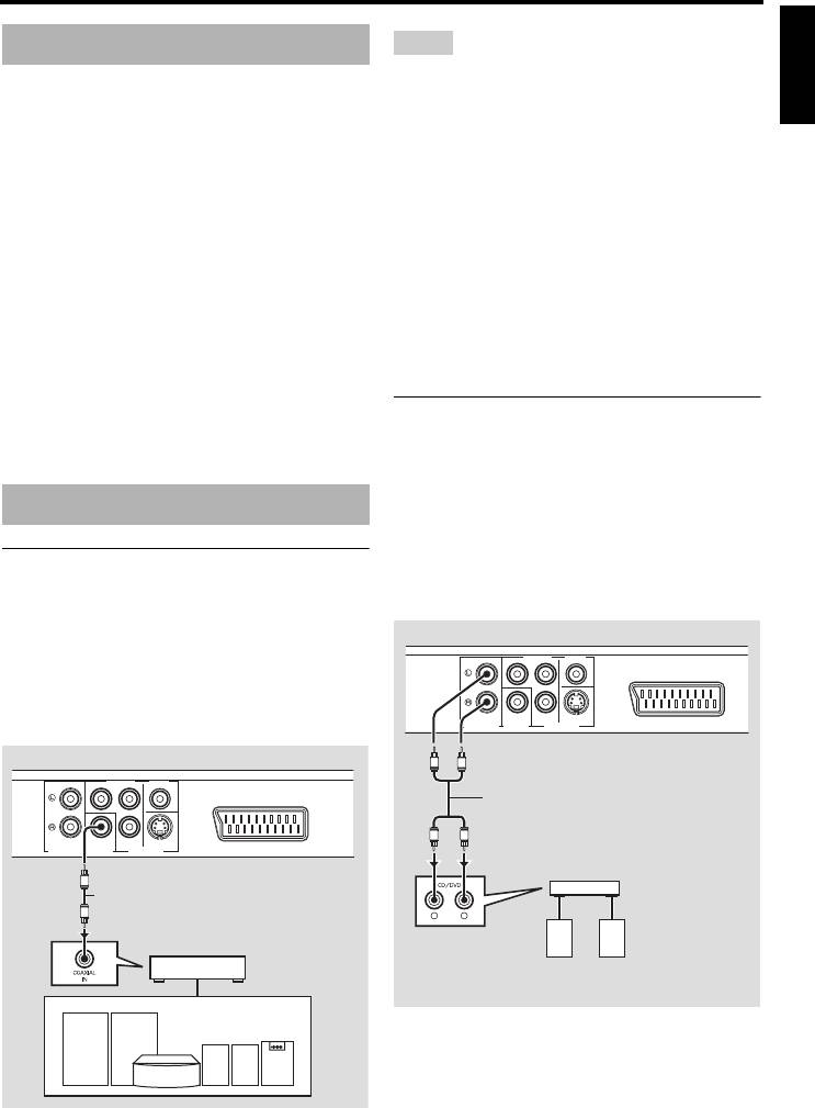
Analog connection
to the phono in jack of your audio system.
This unit has 2-ch analog output jacks.
Connect the AUDIO OUT (L, R) jacks of this
unit to the corresponding input jacks of your
Audio connections
audio component (such as a stereo amplifier)
using the supplied RCA stereo cable (Europe
Digital connection
and Russia models) or audio/video cable
(other models).
This unit has a digital coaxial output jack.
Connect the DIGITAL OUT - COAXIAL jack
This unit (Europe model)
of this unit to your AV receiver equipped with
PR
/ CR
COMPONENT VIDEO
Y
a Dolby Digital or DTS decoder using a
commercially available coaxial digital audio
cable.
COAXIAL
PB
/ CB
S VIDEO
AV
AUDIO OUT
VIDEO OUTDIGITAL OUT
This unit (Europe model)
L
R
RCA stereo cable (Europe and Russia
PR
/ CR
COMPONENT VIDEO
Y
models) or audio/video cable
(other models)
(supplied)
L
R
COAXIAL
PB
/ CB
S VIDEO
AV
AUDIO OUT
VIDEO OUTDIGITAL OUT
Stereo
amplifier
C
Coaxial digital audio cable
C
L
R
AV receiver
Speakers
Speakers
9 En
Connections
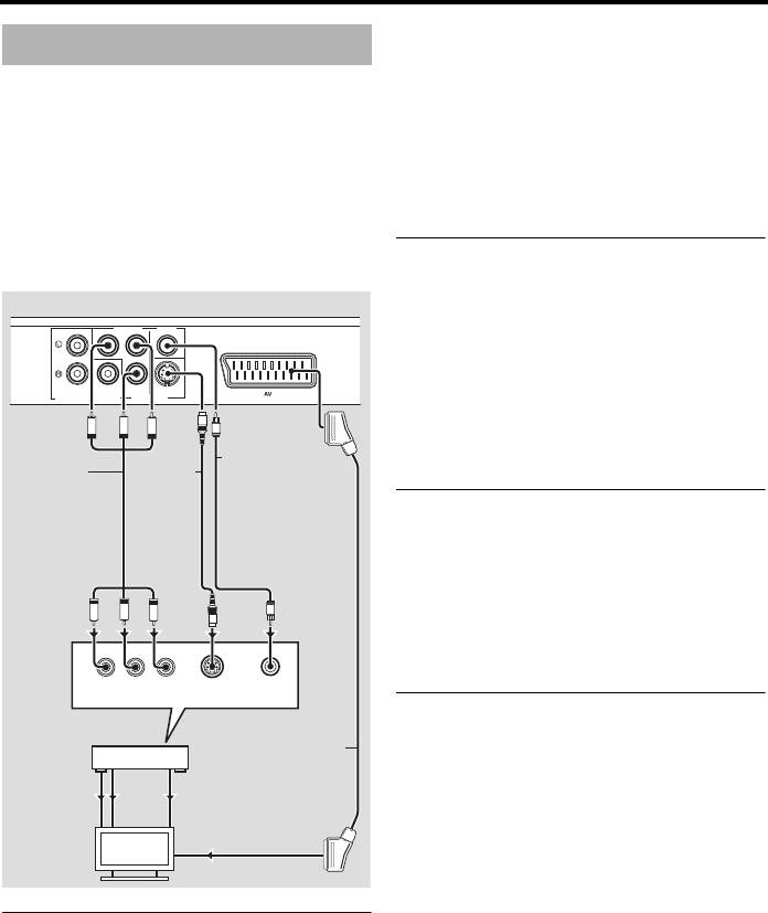
commercially available component video
Video connections
cable. Observe the color of each jack when
you make connections.
Make video connections to your receiver and
If your receiver does not have component
TV so that you can use one TV for several
output jacks, you can achieve a better video
different video sources (LD, VCR, etc.) by
image by connecting the component output
simply switching the input source selector of
jacks of this unit directly to the component
your receiver.
input jacks of your TV.
This unit has several types of video output
jacks. Use the one that corresponds to the
S-video jack <B>
input jacks of the component to be connected.
S-video connections achieve a clearer picture
This unit (Europe model)
than composite video connections by
PR
/ CR
COMPONENT VIDEO
Y
transmitting video signals on separate wires
for luminance (Y) and chrominance (C).
Connect the VIDEO OUT - S VIDEO jack of
COAXIAL
PB
/ CB
S VIDEO
AV
AUDIO OUT
VIDEO OUTDIGITAL OUT
this unit to an S-video input jack of your AV
S
PR
PB
Y
V
receiver and then to that of your TV using a
Composite video
commercially available S-video cable.
Component
cable (Europe and
S-video
video cable
Russia models)
cable
or audio/video
cable
Composite video jack <C>
(other models)
(supplied)
Connect the VIDEO OUT - VIDEO jack of
this unit to a video input jack of your AV
receiver and then to that of your TV using the
<A>
PR
PB
Y
<B>
V
<D><C>
supplied composite video cable (Europe and
S
Russia models) or audio/video cable (other
YPB/CBPR/CR
models).
COMPONENT
S VIDEO
VIDEO
VIDEO IN
INPUT
INPUT
SCART terminal <D>
AV receiver
(Europe and Russia models only)
SCART cable
You may connect the TV directly to this unit.
COMPONENT
S VIDEO
VIDEO
VIDEO OUT
OUT
OUT
Connect the AV terminal of this unit to the
COMPONENT
S VIDEO
VIDEO
SCART input terminal of your TV using a
VIDEO IN
IN
IN
commercially available SCART cable.
TV
The AV terminal outputs composite and RGB
video signals together with 2-ch audio signal.
Set the output of the video signal in
Component video jacks <A>
“Switching YUV/RGB (Europe and Russia
Component video connections achieve higher
models only)” on page 36.
fidelity color reproduction than S-video
connections by transmitting video signals on
separate wires for luminance (Y: green) and
chrominance (PB: blue, PR: red).
Connect the VIDEO OUT - COMPONENT
(Y, PB/CB, PR/CR) jacks of this unit to
component input jacks of your AV receiver
and then to those of your TV using a
10 En
Connections
English
Notes
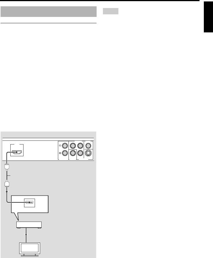
HDMI connection
• You need to set [HDMI AUDIO] (see page 32)
and [HDMI VIDEO] (see page 36) properly.
HDMI jack
• You need to make appropriate audio connections
HDMI (High-Definition Multimedia
if the connected component does not output audio
Interface) provides high quality digital audio
signals (see “Audio connections” on page 9).
and video on a single connection.
• This unit is not compatible with HDCP-
Connect the HDMI jack of this unit to an
incompatible HDMI or DVI components.
HDMI input jack of your AV receiver, and
• You need a commercially available HDMI/DVI
then to that of your TV using a commercially
conversion cable when you connect this unit to
other DVI components. In this case, the HDMI
available HDMI cable.
jack of this unit does not output any audio
If your receiver does not have an HDMI input
signals.
jack, you can achieve a better video image by
• Depending on the connected DVI component,
connecting the HDMI jack of this unit directly
black and white in the image may not be distinct.
to the HDMI input jack of your TV.
In that case, adjust the picture setting of the
This unit can display High-Definition JPEG
connected DVI component.
images (720p, 1080i, or 1080p) when you
• Do not disconnect or turn off the power of the
connect this unit to an HDTV via the HDMI
HDMI/DVI component connected to the HDMI
jack. For details, see “HD JPEG” on page 37.
jack of this unit during playback. Doing so may
disrupt playback or cause noise.
This unit (Europe model)
y
PR
/ CR
COMPONENT VIDEO
Y
HDMI
When connecting an HDMI component, refer to the
manual supplied with your component.
PB
/ CB
S VIDEOCOAXIAL
AUDIO OUT
DIGITAL OUT
VIDEO OUT
HDMI cable
HDMI IN
AV receiver
HDMI OUT
HDMI IN
TV
11 En
Connections
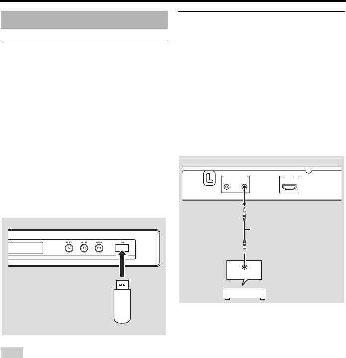
Remote control jacks
Other connections
This unit has remote control input/output
jacks. If your AV receiver is a Yamaha product
USB port
and has the capability to transmit SCENE
This unit has a USB port and can access MP3,
control signals, you can use the SCENE
®
WMA, WMV, JPEG, and DivX
files saved
function.
on your USB device.
Connect the REMOTE CONTROL (IN) jack
Connect a USB connector of your USB device
of this unit to a remote control output jack of
to the USB port on the front panel of this unit.
your receiver using a commercially available
When your USB device is connected to the
monaural 3.5 mm mini plug cable so that this
USB port of this unit, you can record tracks on
unit starts playback automatically by simply
a CD onto your USB device in MP3 format.
pressing a SCENE button of your receiver.
For details, see “Recording CD tracks onto
your USB device” on page 28.
This unit
To disconnect the USB device, press
7
to
MAINS
REMOTE CONTROL
HDMI
stop playback, press USB to return to the disc
OUT
IN
mode, and then disconnect the device from
this unit.
This unit
Monaural 3.5 mm mini plug
cable
REMOTE OUT
AV receiver
USB
device
y
• For details about the SCENE function, refer to
the owner’s manual supplied with your Yamaha
AV receiver.
Note
• You can connect a Yamaha component (such as
This unit may not recognize some USB devices.
DVD player and CD player) corresponds with the
SCENE function to the REMOTE CONTROL
y
(OUT) jack of this unit.
For details about the USB features, see “Using a
USB device” on page 23.
12 En
Оглавление
- Contents Contents
- Contents
- Introduction
- Functional Overview
- Connections
- Getting Started
- Playback Operation
- Setup Menu
- Language Codes
- Troubleshooting
- Glossary
- Specifications
- Содержание Содержание
- Содержание
- Введение
- Функциональный обзор
- Подключения
- Подготовка к эксплуатации
- Управление воспроизведением
- Меню настройки
- Языковые коды
- Устранение неисправностей
- Справочник
- Технические спецификации


