Beurer TL 40 – страница 4
Инструкция к Beurer TL 40
Оглавление
- 1. Для ознакомления 2. Пояснения к символам
- 3. Указание
- Общие указания 4. Описание прибора Обзор 5. Подготовка к работе Установка Настенное крепление
- Подключение к сети 6. Управление
- 7. Чистка прибора и уход за ним 8. Замена люминесцентной лампы 9. Хранение 10. Утилизация
- 11. Что делать при возникновении неполадок? 12. Технические данные
- 13. Гарантия
ELECTROMAGNETIC COMPATIBILITY INFORMATION
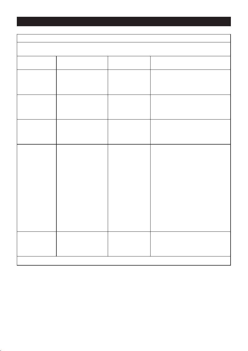
Guidance and manufacturer’s declaration – electromagnetic immunity
The “Mini Daylight” is intended for use in the electromagnetic environment specified below. The customer
or the user of the “Mini Daylight” should ensure that it is used in such an environment.
Immunity test IEC 60601
Compliance
Electromagnetic environment –
test level
level
guidance
Electrostatic
±6 kV contact
±6 kV contact
Floors should be wood, concrete or
discharge (ESD)
±8 kV air
±8 kV air
ceramic tile. If floors are covered with
IEC 61000-4-2
synthetic material, the relative humidity
should be at least 30 %.
Electrical fast
±2 kV for power
±2 kV for power
Mains power quality should be that of
transient/burst
supply lines
supply lines
a typical commercial or hospital envi-
IEC 61000-4-4
±1 kV for input/output
±1 kV for input/
ronment.
lines
output lines
Surge
±1 kV differential mode
±1 kV differential
Mains power quality should be that of
IEC 61000-4-5
±2 kV common mode
mode
a typical commercial or hospital envi-
±2 kV common
ronment.
mode
Voltage dips,
<5 % U
<5 % U
Mains power quality should be that of a
T
T
short interruptions
(>95 % dip in U
T
)
(>95 % dip in U
T
)
typical commercial or hospital environ-
and voltage vari-
for 0,5 cycle
for 0,5 cycle
ment. If the user of the “Mini Daylight”
ations on power
requires continued operation during
supply input lines
40 % U
power mains interruptions, it is recom-
T
40 % U
T
IEC 61000-4-11
(60 % dip in U
T
)
(60 % dip in U
T
)
mended that the “Mini Daylight” be
for 5 cycles
for 5 cycles
powered from an uninterruptible power
supply or a battery.
70 % U
T
70 % U
T
(30 % dip in U
T
)
(30 % dip in U
T
)
for 25 cycles
for 25 cycles
<5 % U
T
<5 % U
T
(>95 % dip in U
T
)
(>95 % dip in U
T
)
for 5 sec
for 5 sec
Power frequency
3 A/m 3 A/m Power frequency magnetic fields
(50/60 Hz)
should be at levels characteristic of a
magnetic field
typical location in a typical commercial
IEC 61000-4-8
or hospital environment.
NOTE U
T
is the a.c. mains voltage prior to application of the test level.
61
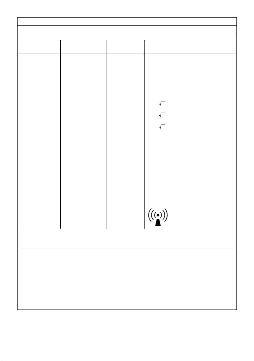
Guidance and manufacturer’s declaration – electromagnetic immunity
The “Mini Daylight” is intended for use in the electromagnetic environment specified below. The customer or
the user of the “Mini Daylight” should ensure that it is used in such an environment.
Immunity test IEC 60601
Compliance
Electromagnetic environment –
test level
level
guidance
Portable and mobile RF communications
equipment should be used no closer to any
part of the “Mini Daylight”, including cables,
than the recommended separation distance
calculated from the equation applicable to
the frequency of the transmitter.
Recommended separation distance
d=1.2 P
Conducted RF
3 V
rms
3 V
150 kHz to 80 MHz
d=1.2 P 80MHz to 800MHz
IEC 61000-4-6
d=2.3 P 800MHz to 2.5 GHz
Radiated RF
3 V/m
3 V/m
IEC 61000-4-3
80 MHz to 2,5 GHz
where P is the maximum output power rating
of the transmitter in watts (W) according
to the transmitter manufacturer and d is
the recommended separation distance in
metres (m).
Field strengths from fixed RF transmitters,
as determined by an electromagnetic site
a
survey,
should be less than the compliance
b
level in each frequency range.
Interference may occur in the vicinity of
equipment marked with the following
symbol:
62
NOTE 1 At 80 MHz and 800 MHz, the higher frequency range applies.
NOTE 2 These guidelines may not apply in all situations. Electromagnetic propagation is affected by absorpti-
on and reflection from structures, objects and people.
a
Field strengths from fixed transmitters, such as base stations for radio (cellular/cordless) telephones and land
mobile radios, amateur radio, AM and FM radio broadcast and TV broadcast cannot be predicted theoretically
with accuracy. To assess the electromagnetic environment due to fixed RF transmitters, an electromagnetic
site survey should be considered. If the measured field strength in the location in which the “Mini Daylight” is
used exceeds the applicable RF compliance level above, the Medical Daylight should be observed to verify
normal operation. If abnormal performance is observed, additional measures may be necessary, such as reori-
enting or relocating the “Mini Daylight”.
b
Over the frequency range 150 kHz to 80 MHz, field strengths should be less than [V1] V/m.
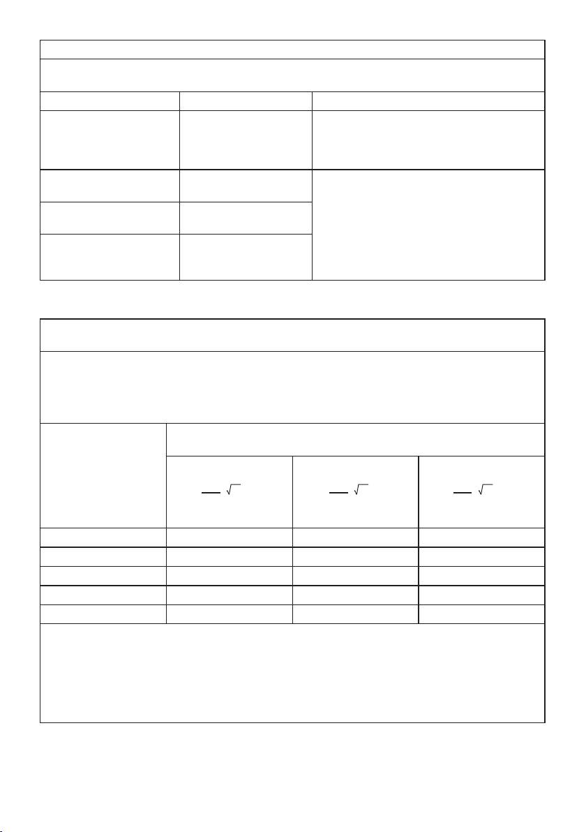
Guidance and manufacturer’s declaration – electromagnetic emissions
The “Mini Daylight” is intended for use in the electromagnetic environment specified below. The
customer or the user of the “Mini Daylight” should ensure that it is used in such an environment.
Emissions test Compliance Electromagnetic environment – guidance
RF emissions
Group 1 The “Mini Daylight” uses RF energy only for its
CISPR 11
internal function. Therefore, its RF emissions are
very low and are not likely to cause any interfe-
rence in nearby electronic equipment.
RF emissions
Class B The “Mini Daylight” is suitable for use in all
CISPR 11
establishments, including domestic establish-
ments and those directly connected to the public
Harmonic emissions
Class A
low-voltage power supply network that supplies
IEC 61000-3-2
buildings used for domestic purposes.
Voltage fluctuations/
Complies
flicker emissions
IEC 61000-3-3
Recommended separation distances between
portable and mobile RF communications equipment and the Mini Daylight
The “Mini Daylight” is intended for use in an electromagnetic environment in which radiated RF disturbances
are controlled. The customer or the user of the Medical Daylight can help prevent electromagnetic interference
by maintaining a minimum distance between portable and mobile RF communications equipment (transmit-
ters) and the “Mini Daylight” as recommended below, according to the maximum output power of the commu-
nications equipment.
Rated maximum output
Separation distance according to frequency of transmitter m
power of
transmitter W
150 kHz to 80 MHz 80 MHz to 800 MHz 800 MHz to 2,5 GHz
3,5
3,5
7
d = P
[ ]
d = P
[ ]
d = P
[ ]
V
E
E
1
1
1
0,01 0.12 0.12 0.23
0,1 0.38 0.38 0.73
1 1.2 1.2 2.3
10 3.8 3.8 7.3
100 12 12 23
For transmitters rated at a maximum output power not listed above, the recommended separation distance d
in meters (m) can be estimated using the equation applicable to the frequency of the transmitter, where P is
the maximum output power rating of the transmitter in watts (W) according to the transmitter manufacturer.
NOTE 1 At 80 MHz and 800 MHz, the separation distance for the higher frequency range applies.
NOTE 2 These guidelines may not apply in all situations. Electromagnetic propagation is affected by absorpti-
on and reflection from structures, objects and people.
63

752.991-1212 Irrtum und Änderungen vorbehalten
64
