Yamaha RX-V365 Silver: PREPARATION
PREPARATION: Yamaha RX-V365 Silver
PREPARATION
Preparation of remote control
Installing batteries in the remote control
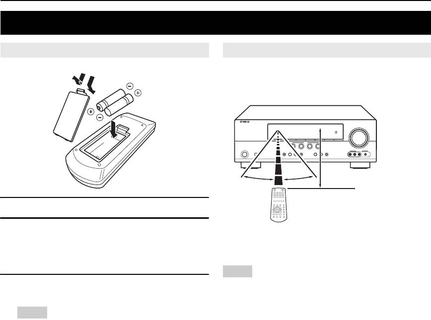
Using the remote control
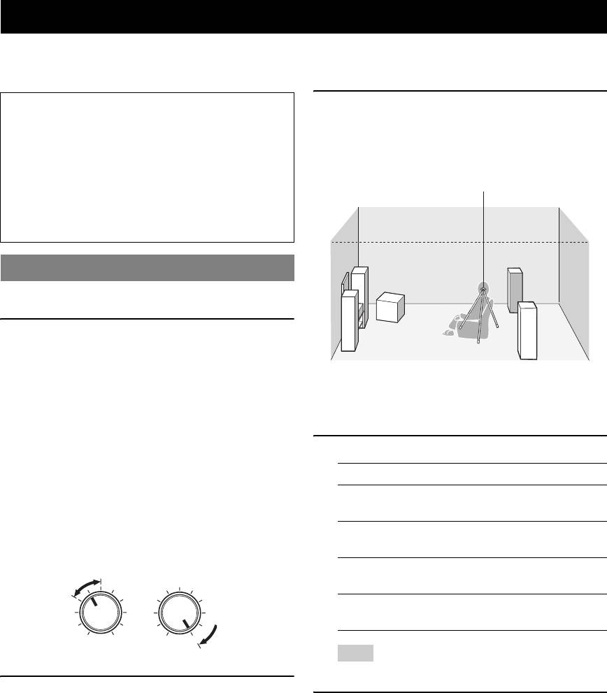
The remote control transmits a directional infrared ray.
Be sure to aim the remote control directly at the remote
1
3
control sensor on this unit during operation.
2
30º 30º
Approximately 6 m (20 ft)
1 Take off the battery compartment cover.
2 Insert the four supplied batteries (AAA, R03,
a Infrared window
UM-4) according to the polarity markings (+
Outputs infrared control signals. Aim this window at the
and –) on the inside of the battery
component you want to operate.
compartment.
Notes
3 Snap the battery compartment cover back
• Do not spill water or other liquids on the remote control.
• Do not drop the remote control.
into place.
• Do not leave or store the remote control in the following types of
conditions:
Notes
– places of high humidity, such as near a bath
• Change all of the batteries if you notice the following conditions:
– places of high temperature, such as near a heater or stove
– the operation range of the remote control decreases.
– places of extremely low temperatures
• Do not use old batteries together with new ones.
– dusty places
• Do not use different types of batteries (such as alkaline and
manganese batteries) together. Read the packaging carefully as
these different types of batteries may have the same shape and
color.
• If the batteries have leaked, dispose of them immediately. Avoid
touching the leaked material or letting it come into contact with
clothing, etc. Clean the battery compartment thoroughly before
installing new batteries.
• Do not throw away batteries with general house waste; dispose of
them correctly in accordance with your local regulations.
8 En
Connections
Placing speakers
Connecting speakers
INTRODUCTION
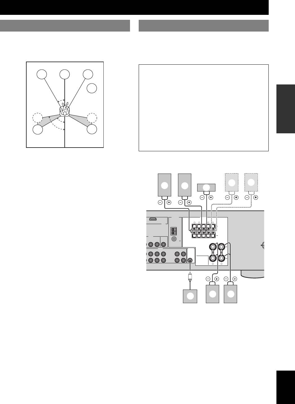
The speaker layout below shows the speaker setting we
Be sure to connect the left channel (L), right channel (R),
recommend. You can use it to enjoy CINEMA DSP and
“+” (red) and “–” (black) properly. If the connections are
multi-channel audio sources.
faulty, this unit cannot reproduce the input sources
accurately.
Caution
FL
C
FR
• Use speakers with the specified impedance shown on
the rear panel of this unit.
SW
PREPARATION
• Before connecting the speakers, make sure that this
30˚
the AC power plug is disconnected from the AC wall
outlet.
• Do not let the bare speakers wires touch each other or
SL
SR
do not let them touch any metal part of this unit. This
60˚
could damage this unit and/or speakers.
80˚
SL
SR
• Use magnetically shielded speakers. If this type of
speaker still creates interference with the monitor,
OPERATION
place the speakers away from the monitor.
BASIC
Front left and right speakers (FL and FR)
■ 5.1-channel speaker connection
The front speakers are used for the main source sound plus
effect sounds. Place these speakers at an equal distance
from the ideal listening position. The distance of each
speaker from each side of the video monitor should be the
same.
OPERATION
ADVANCED
Center speaker (C)
The center speaker is for the center channel sounds
(dialog, vocals, etc.). If for some reason it is not practical
ANTENNA
SPEAKERS
to use a center speaker, you can do without it. Best results,
HDMI
LRLR
however, are obtained with the full system.
VIDEO
Surround left and right speakers (SL and SR)
The surround speakers are used for effect and surround
INFORMATION APPENDIX
AUDIO OUTPUT
ADDITIONAL
sounds.
Subwoofer (SW)
LR
The use of a subwoofer with a built-in amplifier, such as
the Yamaha Active Servo Processing Subwoofer System,
is effective not only for reinforcing bass frequencies from
any or all channels, but also for high fidelity sound
reproduction of the LFE (low-frequency effect) channel
included in Dolby Digital and DTS sources. The position
of the subwoofer is not so critical, because low bass
sounds are not highly directional. But it is better to place
the subwoofer near the front speakers. Turn it slightly
toward the center of the room to reduce wall reflections.
English
9 En
B
L
D
DTV/CBL
SURROUND CENTER FRONT B
DVR
MONITOR
OUT
(PLAY)
IN
CD-R
MD/
OUT
(REC)
WOOFER
SUB
FRONT A
B
f
g
c
d
e
AM
GND
IN
OUT
FM
UNBAL.
75
L DVR CD
IN
OUT
a b
h
Connections
■ Connecting to the FRONT A terminals
Speakers Jacks on this unit
a Front speaker (A) Right* FRONT A (R)
b Front speaker (A) Left* FRONT A (L)
2
c Surround speaker Right SURROUND (R)
Red: positive (+)
1
d Surround speaker Left SURROUND (L)
Black: negative (–)
e Center speaker CENTER
3
f Front speaker (B) Right* FRONT B (R)
g Front speaker (B) Left* FRONT B (L)
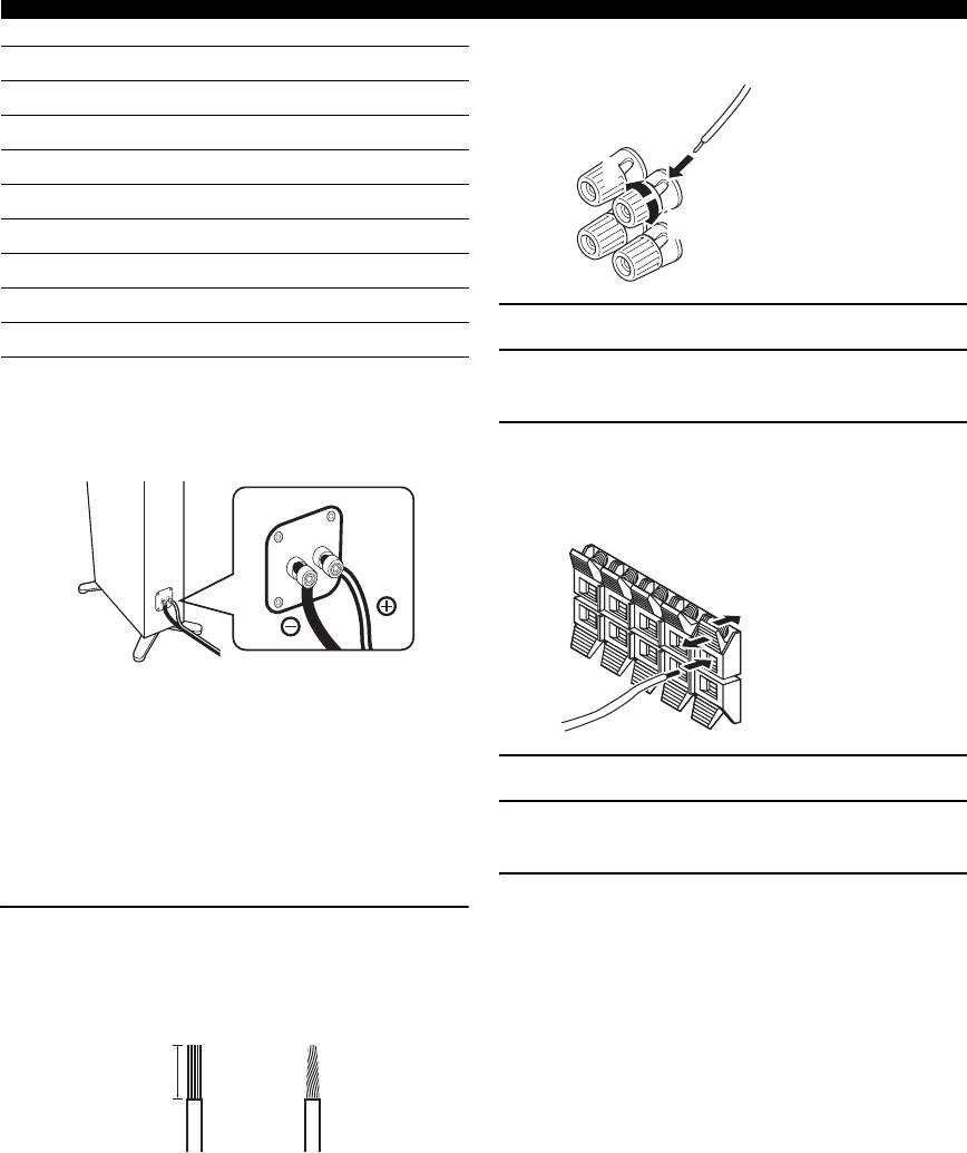
1 Loosen the knob.
h Subwoofer SUBWOOFER
2 Insert the bare end of the speaker wire into
* You can select the front speaker set from Front speakers (A) and Front
speakers (B) by pressing CSPEAKERS repeatedly. See page 19 for
the slit on the terminal.
details.
■ Connect speaker cables to each speaker
3 Tighten the knob to secure the wire.
■ Connecting to the FRONT B, CENTER, and
SURROUND terminals
Red: positive (+)
Black: negative (–)
Cables are colored or shaped differently, perhaps with a
stripe, groove or ridge. Connect the striped (grooved, etc.)
cable to the “+” (red) terminals of your speaker. Connect
the plain cable to the “–” (black) terminals.
1 Press down the tab.
■ Before connecting to the SPEAKERS
2 Insert the bare end of the speaker wire into
terminal
the hole on the terminal.
A speaker cord is actually a pair of insulated cables
running side by side.
3 Release the tab to secure the wire.
Remove approximately 10 mm (3/8”) of insulation
from the end of each speaker cable and then
twist the bare wires of the cable together to
prevent short circuits.
10 mm (3/8”)
10 En
Connections
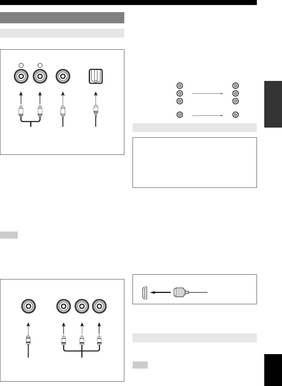
VIDEO jacks
Connecting video components
For conventional composite video signals transmitted via
composite video cables.
Information on jacks and cable plugs
INTRODUCTION
COMPONENT VIDEO jacks
For component signals, separated into the luminance (Y)
Audio jacks and cable plugs
and chrominance (P
B, PR) video signals transmitted on
separate wires of component video cables.
AUDIO
DIGITAL AUDIO
DIGITAL AUDIO
L
R
COAXIAL
OPTICAL
Video signal flow for MONITOR OUT
Output
Input
(MONITOR OUT)
(White) (Red) (Orange)
PR
P
R
PREPARATION
COMPONENT
P
B
P
B
VIDEO
Y
Y
O
L
R
C
VIDEO
Left and right
Coaxial
Optical
Information on HDMI™
analog audio
digital audio
digital
cable plugs
cable plug
audio cable
OPERATION
plug
Audio signals input at the HDMI jack are not output
BASIC
from any speaker terminals but output from the
connected video monitor. To enjoy the sound from
AUDIO jacks
speakers connected to this unit,
For conventional analog audio signals transmitted via left
– make an analog or digital connection besides the
and right analog audio cables. Connect red plugs to the
HDMI connection (see page 13).
right jacks and white plugs to the left jacks.
– mute the volume of the connected video monitor.
OPERATION
ADVANCED
COAXIAL jack
You can play back pictures by connecting your video
For digital audio signals transmitted via coaxial digital
monitor and video source component to this unit using
audio cable.
HDMI connections.
OPTICAL jacks
At that time, audio/video signals output from the
For digital audio signals transmitted via optical digital
connected component (such as DVD player etc.) are
audio cables.
output to the connected video monitor only when this unit
is turned on and set to the input source (DVD or DTV/
INFORMATION APPENDIX
Notes
ADDITIONAL
CBL).
• You can use the digital jacks to input PCM, Dolby Digital, and DTS
bitstreams. All digital input jacks are compatible with digital signals with
Furthermore, available audio/video signals depend on the
up to 96 kHz of sampling frequency.
specification of the connected video monitor. Refer to the
• This unit handles digital and analog signals independently. Thus audio
instruction manual of each connected component.
signals input at the digital jacks are not output at the analog AUDIO OUT
(REC) jack.
■ HDMI jack and cable plug
Video jacks and cable plugs
HDMI
COMPONENT VIDEO
HDMI cable plug
VIDEO
Y P
B
P
R
y
• We recommend using an HDMI cable shorter than 5 meters (16 feet)
(Yellow) (Blue) (Red)(Green)
with the HDMI logo printed on it.
• Use a conversion cable (HDMI jack ↔ DVI-D jack) to connect this unit
to other DVI components.
Using the AUDIO OUT REC jack
V
Y
PB
P
R
You can record the audio signal output at the AUDIO
OUT (REC) jack by using the recording components.
English
Composite
Component
video cable
video cable
Note
plug
plugs
• Check the copyright laws in your country to record from CDs, radio, etc.
Recording of copyrighted material may infringe copyright laws.
11 En
Connections
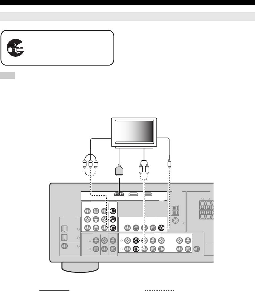
Connecting a TV monitor or projector
Make sure that this unit and other
components are unplugged from the
AC wall outlets.
Note
• If you turn off the video monitor connected to the HDMI OUT jack via a DVI connection, the connection may fail. In this case, the HDMI indicator
flashes irregularly.
ANTENNA
SP
LR
DIGITAL INPUT
VIDEO
MULTI CH INPUT
OUTPUT
L
R
12 En
E
SURROUND C
DVD
DTV/CBL
OPTICAL
CD
3
DTV/
CBL
2
DVD
1
COAXIAL
E
TV
(or projector)
Component
Video
video in
in
HDMI
Audio
in
out
Y
P
B
P
R
V
LR
DVDOUT DTV/CBL
COMPONENT VIDEO
HDMI
DVD DTV/CBL DVR
MONITOR
OUT
AM
P
R
GND
P
B
DVR
MONITOR
IN
OUT
OUT
FM
75
UNBAL.
Y
AUDIO
FRONT CENTER
SURROUND
DVD DTV/CBL DVR CD
IN
MD/
OUT
IN
OUT
(PLAY)
CD-R
(REC)
L
SUB
WOOFER
R
SUBWOOFER
Recommended connections Alternative connections
Connections
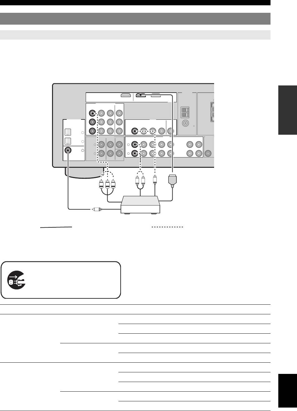
Connecting other components
Connecting audio and video components
INTRODUCTION
This unit has three types of audio jacks, two types of video jacks and HDMI jacks. You can choose the connection
method depending on the component to be connected.
■ Connecting example (connecting a DVD player)
PREPARATION
OPERATION
BASIC
OPERATION
ADVANCED
■ Jacks used for audio and video connections
Recommended connections are indicated by (*). When connecting a recording component, you need to make additional
INFORMATION APPENDIX
ADDITIONAL
connections for recording (signal transmission from this unit to the recording component).
y
• You can also use the VIDEO AUX jacks (see page 14) on the front panel
to connect an additional component.
• To confirm the positions of “jacks on this unit” in the following table,
refer to “Rear panel” in “Functional overview” on page 6.
English
13 En
R
ANTENNA
DVDOUT DTV/CBL
S
HDMI
COMPONENT VIDEO
DVD DTV/CBL DVR
DIGITAL INPUT
VIDEO
DVD
DTV/CBL
OPTICAL
CD
3
AUDIOMULTI CH INPUT
OUTPUT
DTV/
CBL
2
L
L
DVD
1
R
R
COAXIAL
U
MONITOR
OUT
AM
P
R
GND
P
B
DVR
MONITOR
IN
OUT
OUT
FM
75
UNBAL.
Y
FRONT CENTER
SURROUND
DVD
DTV/CBL DVR CD
IN
MD/
OUT
IN
OUT
(PLAY)
CD-R
(REC)
SUB
WOOFER
SUBWOOFER
Component out
Audio out
Video out
L
R
V
Y
P
B
P
R
Coaxial out
HDMI out
C
Recommended connections Alternative connections
Make sure that this unit and other
components are unplugged from the
AC wall outlets.
Component Signal type Jacks on component Jacks on this unit
DVD player or Blu-ray
Video HDMI out* HDMI (DVD)*
Disc player
Component out COMPONENT VIDEO (DVD)
Video out (composite) VIDEO (DVD)
Audio Optical out* COAXIAL (DVD)*
Audio out (analog) AUDIO (DVD)
Set-top box Video HDMI out* HDMI (DTV/CBL)*
Component out COMPONENT VIDEO (DTV/CBL)
Video out (composite) VIDEO (DTV/CBL)
Audio Optical out* OPTICAL (DTV/CBL)*
Analog out (analog) AUDIO (DTV/CBL)
Connections
Component Signal type Jacks on component Jacks on this unit
DVD recorder Video HDMI out* HDMI (DVR)*
Video out (composite) VIDEO (DVR IN)
Audio Audio out (analog)* AUDIO (IN (PLAY))*
Audio recording Audio in (analog)* AUDIO (OUT (REC))*
Video recording Video in (composite)* VIDEO (DVR OUT)*
CD player Audio Coaxial out* OPTICAL (CD)*
Audio out (analog) AUDIO (CD)
MD or CD recorder Audio Audio out (analog)* AUDIO (IN (PLAY))*
Audio recording Audio in (analog)* AUDIO (OUT (REC))*
Notes
• Be sure to make the same type of video connections as those made for your TV if the video conversion is disabled. For example, if you connected your
TV to the VIDEO MONITOR OUT jack of this unit, connect other components to the VIDEO jacks.
• Check the copyright laws in your country to record from CDs, radio, etc. Recording of copyrighted material may infringe copyright laws.
• To make a digital connection to a component other than the default one assigned to each DIGITAL INPUT or DIGITAL OUTPUT jack, configure the
“INPUT ASSIGN” setting (see page 34).
• Only analog audio signals output at AUDIO OUT (REC) jack can be recorded using the recording components. Therefore Digital signals input at the
DIGITAL INPUT jacks or analog signals input at MULTI CH IN jacks can be output at the analog AUDIO OUT (REC) jack for recording.
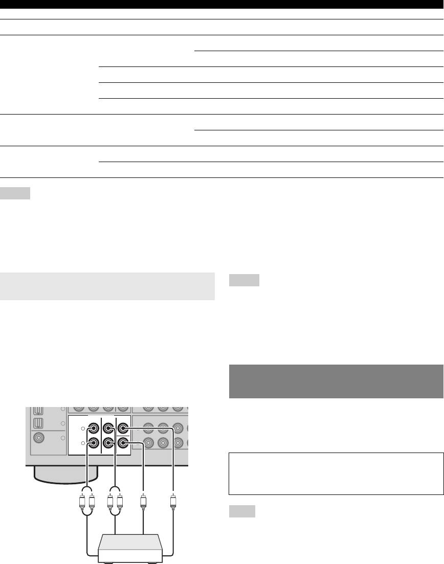
Connecting a multi-format player or an
Notes
external decoder
• When you select the component connected to the MULTI CH INPUT
jacks as the input source (see page 19), this unit automatically turns off
the digital sound field processor, and you cannot select sound field
This unit is equipped with 6 additional input jacks
programs.
(FRONT L/R, SURROUND L/R, CENTER and
• This unit does not redirect signals input at the MULTI CH INPUT jacks
SUBWOOFER) for discrete multi-channel input from a
to accommodate for missing speakers. We recommend that you connect a
5.1-channel speaker system before using this feature.
multi-format player, external decoder or sound processor.
• The source connected to the MULTI CH INPUT jacks on this unit cannot
Connect the output jacks on your multi-format player or
be recorded.
external decoder to the MULTI CH INPUT jacks. Be sure
to match the left and right output jacks to the left and right
input jacks for the front and surround channels.
CD
3
Use the VIDEO AUX jacks on the front panel to connect a
MULTI CH INPUT
FRONT CENTER
SURROUND
DVD
DTV/CBL DV
DTV/
CBL
2
game console or a video camera to this unit. To reproduce
L
L
the source signals input at these jacks, select “V-AUX” as
DVD
1
R
R
the input source.
COAXIAL
SUBWOOFER
Note
• The audio signals input at the PORTABLE mini jack take priority over
the ones input at the AUDIO L/R jacks.
14 En
R
Using the VIDEO AUX jacks on the
front panel
IN
Caution
Be sure to turn down the volume of this unit and other
Subwoofer out
components before making connections.
Surround out
L
R
Front out
L
R
Center out
Multi-format player or
external decoder
Connections
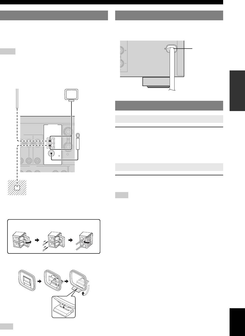
Connecting the FM and AM antennas
Both FM and AM indoor antennas are supplied with this
Once all connections are complete, plug the power cable
INTRODUCTION
unit. In general, these antennas should provide sufficient
into the AC wall outlet.
signal strength. Connect each antenna correctly to the
designated terminals.
Notes
• The AM loop antenna should be placed away from this unit.
• A properly installed outdoor antenna provides clearer reception than an
indoor one. If you experience poor reception quality, install an outdoor
antenna. Consult the nearest authorized Yamaha dealer or service center
about outdoor antennas.
PREPARATION
• The AM loop antenna should always be connected, even if an outdoor
AM antenna is connected to this unit.
OPERATION
BASIC
Press ASTANDBY/ON (or cPOWER) to turn on
this unit.
y
• When you turn on this unit, there will be a 4 to 5-second delay before this
unit can reproduce sound.
OPERATION
ADVANCED
Press ASTANDBY/ON (or bSTANDBY) to turn
off this unit.
Note
• In the standby mode, this unit consumes a small amount of power in
INFORMATION APPENDIX
order to receive infrared signals from the remote control.
ADDITIONAL
Connecting the wire of the AM loop antenna
Assembling the supplied AM loop antenna
English
Note
• The types of the supplied AM loop antenna is different depending on the
models.
15 En
D
ANTENNA
EO
R
SURR
O
AUDIO OUT
P
DVR
CD
S
Connecting the power cable
Outdoor AM antenna
AM loop
Use a 5 to 10 m (16 to 32 ft)
antenna
of vinyl-covered wire
(supplied)
extended outdoors from a
window.
Turning on and off the power
Turning on this unit
N OUT
DVR
MONITOR
OUT
Indoor FM
AM
antenna
GND
(supplied)
FM
75
UNBAL.
IN
MD/
OUT
N
OUT
(PLAY)
CD-R
(REC)
Set this unit to the standby mode
Ground
For maximum safety and minimum
interference, connect the antenna GND
terminal to a good earth ground. A good earth
ground is a metal stake driven into moist earth.
Open the
Insert Close the
lever
lever
L
Power cable
To the AC wall outlet
Optimizing the speaker setting for your listening room (YPAO)
This unit has the Yamaha Parametric Acoustic Optimizer (YPAO). With the YPAO, this unit automatically adjusts output
characteristics of your speakers based on speaker positions, speaker performances, and acoustic characteristics of the
room. We recommend that you first adjust the output characteristics with the YPAO when you use this unit.
Notes
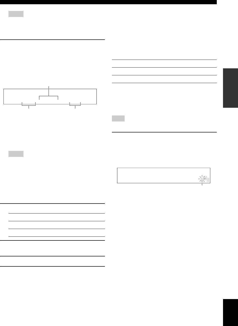
3 Place the optimizer microphone at your
• Be advised that it is normal for loud test tones to be
normal listening position on a flat level
output during the “AUTO SETUP” procedure. Do not
surface with the omni-directional
allow small children to enter the room during the
microphone heading upward.
procedure.
• To achieve the best results, make sure that the room
Optimizer microphone
is as quiet as possible while the “AUTO SETUP”
procedure is in progress. If there is too much ambient
noise, the results may not be satisfactory.
Using AUTO SETUP
y
• Initial settings are indicated by (*) in the following each parameter.
1 Make sure of the following check points.
Before starting the automatic setup, check the
following check points.
• All speakers and subwoofer are connected
y
• We recommend that you use a tripod (etc.) to affix the optimizer
appropriately.
microphone at the same height as your ears would be when you are
• Headphones are disconnected from this unit.
seated in your listening position. You can use the attached screw of
• This unit is turned on.
a tripod (etc.) to fix the optimizer microphone to the tripod (etc.).
• The connected subwoofer is tuned on and the
4 Press ol / h to select “AUTO.”
volume level is set to about half way (or slightly
less).
Choice Function
• FRONT A speakers are selected as the front
AUTO* Automatically runs the entire “AUTO
speaker system (see page 19).
SETUP” procedure.
• The room is sufficiently quiet.
• The crossover frequency control of the connected
RELOAD Reloads the last “AUTO SETUP” settings and
subwoofer is set to the maximum.
overrides the previous settings.
UNDO Undoes the last “AUTO SETUP” settings and
VOLUME
CROSSOVER
HIGH CUT
restores the previous settings.
DEFAULT Resets the “AUTO SETUP” parameters to the
initial factory settings.
MIN
MAX
MIN MAX
Controls of a subwoofer (example)
Note
• “RELOAD” or “UNDO” is available only when you have
previously run “AUTO SETUP” and confirmed the results.
2 Connect the supplied optimizer microphone
to the OPTIMIZER MIC jack on the front
5 Press oENTER to start the setup
panel.
procedure.
“SETUP•••••AUTO” appears on the front panel
This unit starts the automatic setup procedure. Loud
display.
test tones are output from each speaker during the
audio setup procedure. After all settings
(“INITIALIZING,” “WIRING/LEVEL,”
“DISTANCE,” “SIZE”) are sequentially completed,
“FINISH” appears on the front panel display.
y
• To cancel the automatic setup, press ok.
16 En
Optimizing the speaker setting for your listening room (YPAO)
■ If an error screen appears
Notes
If this unit detects the potential problems, an error
• During the automatic setup procedure, do not perform any
message appears on the front panel display during the
operation on this unit.
• We recommend that you get out of the room while this unit is in the
automatic setup.
INTRODUCTION
auto setup procedure. It takes approximately 3 minutes for this unit
For details about each error message, see the “AUTO
to complete the auto setup procedure.
SETUP” section in “Troubleshooting” on page 41.
6 When all measurements are completed
After a few seconds later, the following choices appear.
successfully, “FINISH” appears on the front
Press ol / h to select “RETRY” or “EXIT” and then
press oENTER.
panel display.
The result of the automatic setup for each speaker
Choice Function
appears in order on the front panel display.
RETRY* Starts the “AUTO SETUP” again.
PREPARATION
The distance between the speaker
EXIT Exits from the “AUTO SETUP” procedure.
and the listening position
■ If “WARNING” appears
When this unit detects potential problems during the
automatic setup procedure, “WARNING” appears on the
FL: 3.3m +2
front panel display after result of each speaker. Check the
Speaker
The result of the
warning messages to correct your speaker settings.
FL/FR: Front left/right
adjustment of the
OPERATION
C: Center
volume level
Note
SL/SR: Surround left/right
BASIC
SW: Subwoofer
• Warnings differ from errors in that warnings do not cancel the automatic
setup procedure.
Press on to display the detailed information
y
• To display the result of the automatic setup again, press lk / n
about the warning.
repeatedly.
The detailed information about the warning is displayed
Notes
and the indicators of inapplicable speakers blink on the
OPERATION
ADVANCED
• If you select “RELOAD” in step 4, no test tones are output.
front panel display.
• If an error occurs during the “AUTO:CHECK” procedure, the
setup procedure is canceled and an error screen appears. For
details, see “If an error screen appears” on page 17.
• When this unit detects potential problems during the “AUTO
LFE
SETUP” procedure, “WARNING” and the warning messages
LCR
PHASE REVERSED
SL SR
appear after this unit displays the result of the automatic setup. For
details, refer to the “AUTO SETUP” section in “Troubleshooting”
Flashes
on page 41.
• The distance measurement result may be longer than the actual
y
INFORMATION APPENDIX
distance depending on the characteristics of your subwoofer.
ADDITIONAL
• For details about each warning message, see the “AUTO SETUP” section
in “Troubleshooting” on page 41.
7 Press ol / h to select “SET” or “CANCEL.”
Choice Function
SET* Confirms the “AUTO SETUP” results.
CANCEL Cancels the “AUTO SETUP” results.
8 Press oENTER to confirm your selection.
“AUTO SETUP” appears on the front panel display.
9 Press kMENU to exit from “SET MENU.”
10 Disconnect the optimizer microphone from
this unit.
The optimizer microphone is sensitive to heat. Keep it
away from direct sunlight and do not place it on top
of this unit.
y
English
• If you change speakers, speaker positions, or the layout of your
listening environment, run “AUTO SETUP” again to recalibrate
your system.
• When you want to check the result of the automatic setup in detail
or manually adjust the parameters, use “MANUAL SETUP” (see
page 32).
17 En


")