Yamaha RX-V365 Silver: INTRODUCTION
INTRODUCTION: Yamaha RX-V365 Silver

INTRODUCTION
Features
Built-in 5-channel power amplifier
◆ Minimum RMS output power
(1 kHz, 0.9% THD, 6 Ω)
Front: 100 W/ch
“HDMI,” the “HDMI” logo and “High-Definition
Center: 100 W
Multimedia Interface” are trademarks, or registered
Surround: 100 W/ch
trademarks of HDMI Licensing LLC.
Various input/output connectors
◆ HDMI (IN x 2, OUT x 1), Component video (IN x 3, OUT x
1), Composite video (IN x 3, OUT x 2), Coaxial digital audio
“SILENT CINEMA” is a trademark of Yamaha
(IN x 1), Optical digital audio (IN x 2), Analog audio (IN x 9,
Corporation.
OUT x 2)
◆ Speaker out (5-channel), Subwoofer out
◆ Discrete multi-channel input (6-channel)
Supplied accessories
SCENE select function
◆ Preset SCENE templates for various situations
Check that you received all of the following parts.
◆ SCENE template customizing capability
❏ Remote control
Sound field programs
❏ Batteries (2) (AAA, R03, UM-4)
◆ Proprietary Yamaha technology for the creation of surround
❏ AM loop antenna
field
◆ Compressed Music Enhancer mode
❏ Indoor FM antenna
◆ SILENT CINEMA™
❏ Optimizer microphone
Decoders and DSP circuits
◆ Dolby Digital decoder
◆ Dolby Pro Logic/Dolby Pro Logic II decoder
◆ DTS decoder
◆ Virtual CINEMA DSP
◆ SILENT CINEMA™
Sophisticated FM/AM tuner
◆ 40-station random and direct preset tuning
◆ Automatic preset tuning
HDMI™ (High-Definition Multimedia Interface)
◆ HDMI interface for standard, enhanced or high-definition
video (includes 1080p video signal transmission)
Other features
◆ 192-kHz/24-bit D/A converter
◆ Sleep timer
◆ Cinema and music night listening modes
◆ Remote control capability
Manufactured under license from Dolby Laboratories.
“Dolby,” “Pro Logic,” and the double-D symbol are
trademarks of Dolby Laboratories.
Manufactured under license under U.S. Patent No’s:
5,451,942;5,956,674;5,974,380;5,978,762;6,487,535 and
other U.S. and worldwide patents issued and pending.
DTS is a registered trademark and the DTS logos and
symbol are trademarks of DTS, Inc. © 1996-2007 DTS,
Inc. All Rights Reserved.
2 En
Functional overview
Front panel
INTRODUCTION
VOLUME
OPTIMIZER
MIC
PREPARATION
SPEAKERS
PRESET/TUNING
EDIT
A/B/C/D/E
l
PRESET/TUNING
h
BAND
MEMORY
TUNING
AUTO/MAN'L
SCENE
1
2
3
4
PHONES
TONE
CONTROL
PROGRAM
STRAIGHT
INPUT
NIGHT
VIDEO
AUX
STANDBY
/ON
l
h
l
h
SILENT
CINEMA
EFFECT
VIDEO
AUDIO
PORTABLE
OPERATION
BASIC
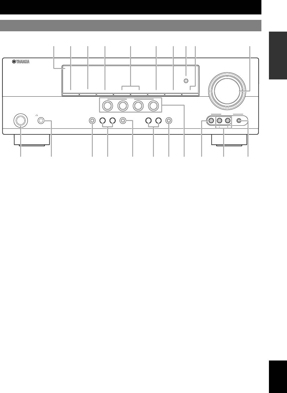
A
A STANDBY/ON
P VOLUME control
Turns on this unit, or sets it to standby mode (see page 15).
Adjusts the volume level of this unit (see page 18).
B PHONES jack
Q VIDEO (VIDEO AUX) jack
Connect to a pair of headphones (see page 20).
Connects to a game console or a video camera using a
OPERATION
ADVANCED
composite video cable (see page 14).
C SPEAKERS
Turns on or off the set of front speakers connected to the
R AUDIO L/R (VIDEO AUX) jacks
FRONT A or FRONT B speaker terminals (see page 19).
Connects to a game console or a video camera using analog
audio cables (see page 14).
D EDIT PRESET/TUNING
Switches the tuning mode (see page 27).
S PORTABLE (VIDEO AUX) jack
Connects to an audio component (such as iPod) (see page 14).
E A/B/C/D/E
Selects the preset station group (A to E) (see page 28).
T OPTIMIZER MIC jack
INFORMATION APPENDIX
Connect to the supplied optimizer microphone (see page 16).
F PRESET/TUNING l / h
ADDITIONAL
Tunes into radio stations manually or automatically and selects a
U Front panel display
preset station group (see page 27).
Shows information about the operational status of this unit (see
page 18).
G BAND
Selects the reception band from FM and AM (see page 27).
H MEMORY
Stores a station that you tuned into as a preset station (see
page 27).
I TUNING AUTO/MAN’L
Selects a tuning method from automatic or manual tuning (see
page 27).
J SCENE 1/2/3/4
Recalls an input source and a sound field program assigned to
each SCENE button (see page 22).
K TONE CONTROL
Selects “BASS” and “TREBLE” to adjust frequency response
(see page 20).
L PROGRAM l / h
Selects a sound field program (see page 25).
M STRAIGHT
Activates the “STRAIGHT” mode (see page 26).
English
N INPUT l / h
Selects an input source (see page 18).
O NIGHT
Selects a night listening mode (see page 20).
3 En
C D G H T
K OL N
IU PE F
J Q SB RM
Functional overview
Front panel display
DVR DVD CD
V-AUX DTV/CBL
MD/CD-R
TUNER
t
YPAO
AUTO
TUNED
STEREO
MEMORY
VOLUME
VIRTUAL
SP
SILENT CINEMA
PRESET
ENHANCER
A B
NIGHT
PSHOLD RT
PTYPTY
CT
EON
SLEEP
MUTE
dB
q
DIGITAL
LFE
ft
q
PL
q
PL
LCR
mS
PCM
SL SR
dB
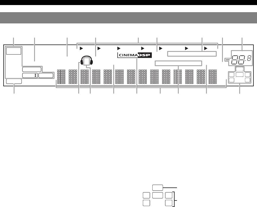
a Decoder indicator
p Radio Data System indicators (Europe and Russia
Lights up when any of the decoders of this unit functions.
models only)
b ENHANCER indicator
• PTY HOLD
Lights up when the Compressed Music Enhancer mode is
Lights up when this unit is in the PTY SEEK mode (see
selected (see page 25).
page 29).
• PS, PTY, RT and CT
c VIRTUAL indicator
Light up according to the available Radio Data System
Lights up when Virtual CINEMA DSP is active (see page 26).
information.
d SILENT CINEMA indicator
•EON
Lights up when headphones are connected and a sound field
Lights up when the EON data service is available.
program is selected (see page 26).
q SLEEP indicator
e Input source indicators
Lights up while the sleep timer is on (see page 21).
The corresponding cursor lights up to show the currently
r Input channel and speaker indicators
selected input source.
f YPAO indicator
Lights up when you run “AUTO SETUP” and when the speaker
settings set in “AUTO SETUP” are used without any
modifications (see page 16).
• LFE indicator
g Tuner indicators
Lights up when the input signal contains the LFE signal.
Lights up when this unit is in the FM or AM tuning mode (see
• Input channel indicators
page 27).
Indicates the channel components of the current digital input
h MUTE indicator
signal.
Flashes while the MUTE function is on (see page 20).
i VOLUME level indicator
Indicates the current volume level.
j PCM indicator
Lights up when this unit is reproducing PCM (Pulse Code
Modulation) digital audio signals.
k Headphones indicator
Lights up when headphones are connected (see page 20).
l SP A B indicators
Lights up according to the set of front speakers selected (see
page 18).
m NIGHT indicator
Lights up when you select a night listening mode (see page 20).
n CINEMA DSP indicator
Lights up when you select a sound filed program (see page 26).
o Multi-information display
Shows the name of the current sound field program and other
information when adjusting or changing settings.
4 En
ab c d feghi
jklmnoqr
p
LFE indicator
LFE
LCR
Input channel indicators
SL SR
Functional overview
Remote control
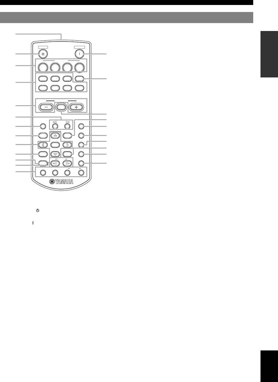
n AUDIO SEL
Selects an audio input select setting for each input source (see
INTRODUCTION
page 19).
STANDBY
POWER
o Cursors (l / h / n / k) / ENTER
• Press cursors to navigate the set menu (see page 32).
• Press ENTER to confirm a selection in the set menu (see
SCENE
page 32).
1234
p NIGHT
CD
MD/CD-R
TUNER
MULTI CH IN
Selects a night listening mode (see page 20).
DVD
DTV/CBL
DVR
V-AUX
q RETURN
PREPARATION
Returns the previous menu level in the set menu mode (see
page 32).
VOLUME
r SUR.DECODE
MUTE
Selects a decoder from four decoders (see page 26).
s DISPLAY
Is not available for this unit.
A/B/C/D/E
PRESET
SLEEP
t STRAIGHT
LEVEL
MENU
AUDIO SEL
Activates the “STRAIGHT” mode (see page 26).
OPERATION
u PROG l / h
NIGHT
BASIC
ENTER
Selects the sound field program (see page 25).
RETURN
DISPLAY
SUR.DECODE
v ENHANCER
Sets the sound field program to the “Music Enh. 2ch” or “Music
STRAIGHT
PROG
ENHANCER
Enh. 5ch” (see page 25).
INFO EON
MODE
PTY
SEEK
START
w INFO/Radio data system control
Controls the Radio Data System with 4-buttons (INFO/EON/
MODE (PTY-SEEK)/START (PTY-SEEK)) (see page 29).
OPERATION
ADVANCED
a Infrared window
Outputs infrared control signals (see page 8).
b STANDBY ( )
Sets this unit to the standby mode (see page 15).
c POWER ( )
Turns this unit on (see page 15).
INFORMATION APPENDIX
ADDITIONAL
d SCENE 1/2/3/4
Recalls an input source and a sound field program assigned to
each SCENE button (see page 22).
e Input selector buttons
Switches the input source to each source (see page 18).
f MULTI CH IN
Sets the input source to MULTI CH IN (see page 19).
g VOLUME +/–
Adjusts the volume level of this unit (see page 18).
h MUTE
Mutes audio output. Press the button again to resume audio
output (see page 20).
i PRESET l / h
Tunes into radio stations manually or automatically and selects a
Preset station number (1 to 8) (see page 27).
j A/B/C/D/E
Selects the preset station group (A to E) (see page 28).
k MENU
Displays the set menu on the front panel display (see page 32).
l SLEEP
English
Sets the sleep timer (see page 21).
m LEVEL
Selects the speaker that you want to adjust (see page 20).
5 En
a
b
c
d
f
e
g
h
i
k
j
l
m
n
p
o
s
q
r
t
v
u
w
Functional overview
Rear panel
ANTENNA
SPEAKERS
OUT
DVD
DTV/CBL
SURROUND
CENTER
FRONT B
COMPONENT VIDEO
HDMI
DVD
DTV/CBL
DVR
MONITOR
OUT
AM
P
R
GND
DIGITAL INPUT
VIDEO
P
B
DVD
DTV/CBL
DVR
MONITOR
IN
OUT
OUT
FM
OPTICAL
UNBAL.
CD
Y
MULTI CH INPUT
AUDIO
FRONT
SURROUND
CENTER
DVD
DTV/CBL
DVR
CD
IN
MD/
OUT
OUTPUT
DTV/
IN
OUT
(PLAY)
CD-R
(REC)
CBL
SUB
WOOFR
DVD
COAXIAL
SUBWOOFER
FRONT A
f g h i
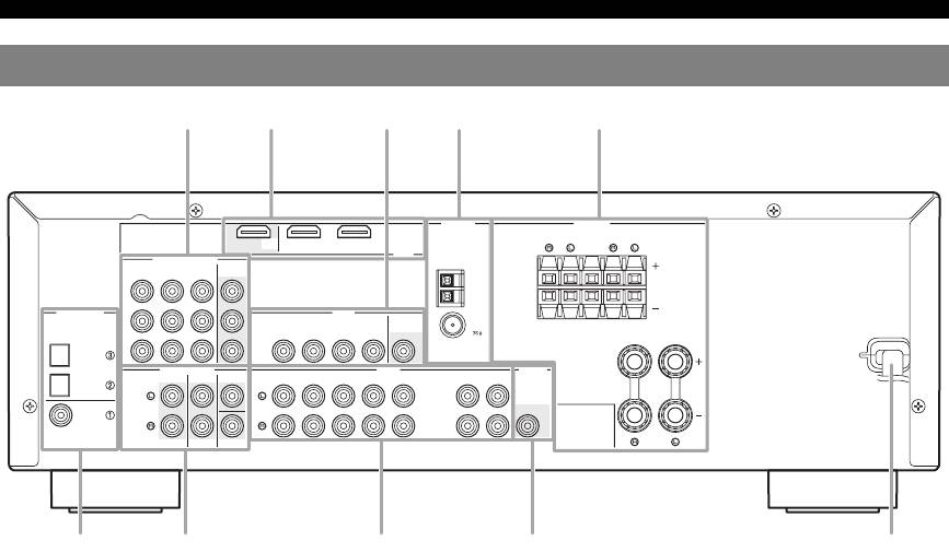
a COMPONENT VIDEO jacks
g MULTI CH INPUT jacks
Connect to Y, PB/CB and PR/CR jacks on your video components
Connect to the output jacks on your multi-format player or
with component video cables (see page 11).
external decoder with analog audio cables (see page 14).
• DVD input jacks
• FRONT L/R jack
• DTV/CBL input jacks
• SURROUND L/R jack
• DVR input jacks
•CENTER jack
• MONITOR OUT output jacks
• SUBWOOFER jack
b HDMI terminals
h AUDIO jacks
Connect to HDMI output/input terminals on your external
Connect to the audio output/input jacks on your components
components with HDMI cables (see page 11).
with analog audio cables (see page 11).
• HDMI DVD terminal
• DVD L/R jack
• HDMI DTV/CBL terminal
• DTV/CBL L/R jack
• HDMI OUT output terminal
• DVR IN L/R jack
c VIDEO jacks
• DVR OUT L/R jack
• CD L/R jack
Connect to video jacks on your video components with
• IN (PLAY) L/R jack
composite video cables (see page 11).
• OUT (REC) L/R jack
• DVD input jack
• DTV/CBL input jack
i SUBWOOFER OUTPUT jack
• DVR IN jack
Connect to a Subwoofer with an analog audio cable (see
• DVR OUT jack
page 9).
• MONITOR OUT jack
j Power cable
d ANTENNA terminals
Connect to a standard AC outlet (see page 15).
Connect to the supplied FM and AM antennas (see page 15).
e SPEAKERS terminals
Connect to each speakers (see page 9).
• FRONT A L/R
• FRONT B L/R
• SURROUND L/R
• CENTER
f DIGITAL INPUT jacks
Connect to the DIGITAL output jacks on your digital audio
components with Coaxial/Optical digital audio cables.
This input jacks support PCM, Dolby Digital and DTS bitstream
(see page 11).
• COAXIAL (DVD)
• OPTICAL (DTV/CBL)
• OPTICAL (CD)
6 En
d eb ca
j

Quick start guide
The following steps describe the easiest way to operate this unit. See the related pages for details on the operation and
settings.
INTRODUCTION
Step 1: Check the items
Step 3: Connect your components
In these steps, you need the following items which are not
Connect your TV, DVD player or other components.
included in the package of this unit.
• Connecting a TV monitor or projector ☞P. 1 2
❏ Speakers
• Connecting audio and video components ☞P. 1 3
We recommend magnetically shielded speakers.
• Connecting a multi-format player or an external
decoder ☞P. 1 4
❏ Front speaker ..................................... x 2
• Using the VIDEO AUX jacks on the front panel
PREPARATION
At least two front speakers are required to start
☞P. 1 4
playback.
• Connecting the FM and AM antennas ☞P. 1 5
❏ Center speaker ................................... x 1
❏ Surround speaker .............................. x 2
Step 4: Turn on the power
❏ Active subwoofer ................................... x 1
Connect the power cable and turn on this unit.
Select an active subwoofer equipped with an RCA
input jack.
• Connecting the power cable ☞P. 1 5
OPERATION
• Turning on and off the power ☞P. 1 5
❏ Speaker cable ......................................... x 5
BASIC
❏ Subwoofer cable ..................................... x 1
Select a monaural RCA cable.
Step 5: Select the input source and start
playback
❏ DVD player .............................................. x 1
Select DVD player equipped with coaxial digital
Select the component connected in the step 3 as an input
audio output jack and composite video output jack.
source and start playback.
OPERATION
ADVANCED
❏ Video monitor ......................................... x 1
• Basic procedure ☞P. 1 8
Select a TV monitor, video monitor or projector
• Selecting the SCENE templates ☞P. 2 2
equipped with a composite video input jack.
• Adjusting the sound field programs ☞P. 2 5
❏ Video cable ............................................. x 2
Select an RCA composite video cable.
❏ Digital coaxial audio cable .................... x 1
INFORMATION APPENDIX
ADDITIONAL
Step 2: Set up your speakers
Place your speakers in the room and connect them to this
unit.
Front right
speaker
Video monitor
Subwoofer
Front left
speaker
Surround right
speaker
Center speaker
DVD player
Surround left
speaker
English
• Placing speakers ☞P. 9
• Connecting speakers ☞P. 9
7 En


")