Sony CPD-E100E: Identifying parts and controls RearFront
Identifying parts and controls RearFront: Sony CPD-E100E
Table of contents
- Owner’s Record
- Table of Contents
- Precautions
- Identifying parts and controls RearFront
- Setup Step 1:Connect your monitor to your computer Step 2:Connect the power cord
- Step 3:Turn on the monitor and Selecting the on-screen menu computer language (LANGUAGE/ INFORMATION)
- Customizing Your Monitor Navigating the menu
- Adjusting the brightness and contrast
- Adjusting the horizontal size or Adjusting the curvature of the centering of the picture (H-SIZE/ picture’s sides (PIN/PIN BALANCE) CENTER) Adjusting the angle of the picture’s sides (KEY/KEY BALANCE) Adjusting the vertical size or centering of the picture (V-SIZE/ CENTER)
- Adjusting the picture’s rotation Adjusting the color of the picture (ROTATION) (COLOR) Enlarging or reducing the picture (ZOOM)
- Additional settings (DEGAUSS/ Resetting the adjustments CANCEL MOIRE)
- Technical Features Troubleshooting
- Trouble symptoms and remedies Symptom Check these items
- Symptom Check these items
- Self-diagnosis function Specifications
C:\WIN95-E\DESKTOP\CPD E100\386765911CPDE100EAEP\01GB03BAS-AEP.fm
masterpage:Right
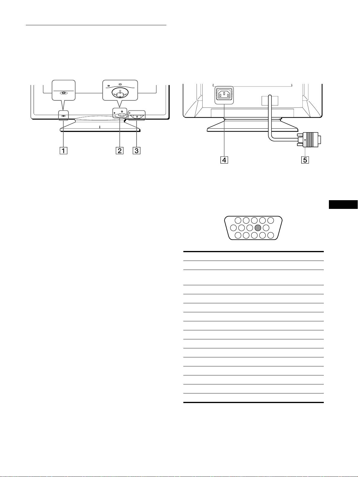
Identifying parts and controls
See the pages in parentheses for further details.
RearFront
MENU
RESET
AC IN
MENU
RESET
1 RESET button (page 12)
4 AC IN connector (page 6)
This button resets the adjustments to the factory settings.
This connector provides AC power to the monitor.
2 Control button (page 9)
5 Video input connector (HD15) (page 6)
The control button is used to display the menu and make
This connector inputs RGB video signals (0.700 Vp-p,
GB
adjustments to the monitor, including brightness and contrast
positive) and sync signals.
adjustments.
3 1 (power) switch and indicator (pages 7, 13, 16)
This button turns the monitor on and off. The power indicator
lights up in green when the monitor is turned on, and either
flashes in green and orange, or lights up in orange when the
monitor is in power saving mode.
Pin No. Signal
1Red
2 Green
(Sync on Green)
3Blue
4 ID (Ground)
5 DDC Ground*
6 Red Ground
7 Green Ground
8 Blue Ground
9–
10 Ground
11 ID (Ground)
12 Bi-Directional Data (SDA)*
13 H. Sync
14 V. Sync
15 Data Clock (SCL)*
* DDC (Display Data Channel) is a standard of VESA.
5
3-867-659-
CPD-E100E
11
(1)
1 2 3 4
5
876
9
10
11 12 13 14 15
