JVC GR-PD1 – страница 4
Инструкция к Видеокамере JVC GR-PD1
Master Page: Right
GR-PD1PAL_07Advanced.fm Page 61 Thursday, June 19, 2003 2:05 PM
EN 61
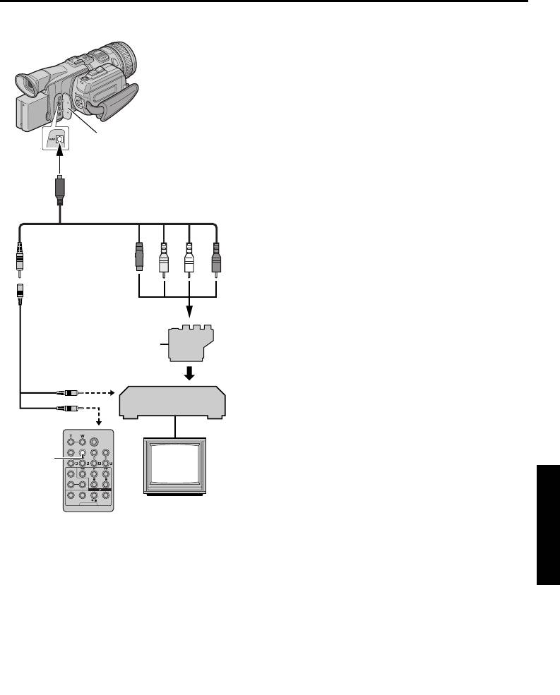
Make Connections
1 A A JVC VCR equipped with a Remote PAUSE
connector…
Also refer to page 24.
…Connect the editing cable to the Remote
PAUSE connector.
B A JVC VCR not equipped with a Remote
PAUSE connector but equipped with an
R.A.EDIT connector…
…Connect the editing cable to the R.A.EDIT
connector.
C A VCR other than above…
Connector Cover***
…Connect the editing cable to the remote
control’s PAUSE IN connector.
To S /AV
2 Insert a recorded tape into the camcorder.
3 Set the Playback Mode Switch to “VIDEO”.
4 Set the Power Switch to “P” while pressing
down the Lock Button located on the switch.
S/AV/Editing cable
5 Turn the VCR power on, insert a recordable tape
(provided)
and engage the AUX mode.
● Refer to the VCR’s instructions.
123 4
NOTES:
Editing extension
● Before Random Assemble Editing, make sure the
cable (provided)****
indications do not appear on the TV monitor. If
they do, they will be recorded onto the new tape.
To choose whether or not the following displays
“Y/C”/“CVBS” Video Out
Select Switch
appear on the connected TV…
Cable
• Date/time
Adapter*
ABTo Re mote PAUSE
Set “DATE/TIME” to “AUTO”, “ON” or “OFF”.
or R.A.EDIT
(墌 pg. 33, 40) Or, press DISPLAY on the remote
control to turn on/off the date indication.
VCR
• Time code
CTo PAUSE IN
Set “TIME CODE” to “OFF” or “ON”.
(墌 pg. 33, 40)
• Indications other than date/time and time code
ADVANCED FEATURES
DISPLAY
TV
Set “ON SCREEN” to “OFF”, “LCD” or “LCD/
TV”. (墌 pg. 33, 40)
A Black to S-VIDEO IN**
B Yellow to VIDEO IN
C White to AUDIO L IN
D Red to AUDIO R IN
* If your VCR has a SCART connector, use the
provided cable adapter.
** Connect when your TV/VCR has an S-VIDEO IN
connector. In this case, it is not necessary to
connect the yellow video cable.
*** When connecting the cable, open the cover.
****If necessary, use this cable for connections.
NOTE:
Set the video out select switch of the cable adapter
as required:
Y/C:
When connecting to a TV or VCR which accepts
Y/C signals and uses an S-Video cable.
CVBS:
When connecting to a TV or VCR which does
not accept Y/C signals and uses an audio/video cable.
CONTINUED ON NEXT PAGE
Master Page: Left
GR-PD1PAL.book Page 62 Tuesday, June 17, 2003 7:31 PM
62 EN
USING THE REMOTE CONTROL UNIT (cont.)
Select Scenes
● If the search time for an in-point exceeds
5 minutes, the recording deck’s Record-Standby
mode will be cancelled and editing will not take
place.
● If there are blank portions before or after the Edit-
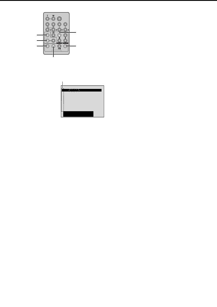
PLAY
In and Edit-Out points, a blue screen may be
FADE/WIPE
included in the edited version.
EFFECT
● Since time codes register time only as accurately
EDIT IN/OUT
R.A.EDIT
as seconds, the time code total time may not
ON/OFF
match the total program time exactly.
CANCEL
● Turning off the camcorder’s power erases all
registered Edit-In and Edit-Out points.
6 Press PLAY (U) and then press R.A.EDIT ON/OFF
● If you select Sepia or Monotone mode from
on the remote control.
Special Effects, you cannot use the Dissolve or
The Random Assemble
Selected parameter
Black & White Fader. In this case the Dissolve or
Editing Menu appears.
Black & White indicator begins blinking. Once the
NIOUT
MODE
7 If using a Wipe/Fader at
1
––
–– : –– ~
next Edit-In point is registered, the effect is turned
2
~
the beginning of the
3
~
off. To combine these effects, use Sepia or
scene, press FADE/WIPE
4
~
5
~
Monotone during recording, then use the Dissolve
on the remote control.
6
~
7
~
or Black & White Fader during Random Assemble
● Cycle through the
8
~
CODETIME
–
–
:
––
Editing.
effects by pressing
TOTAL
0
:
000
● It is not possible to use Wipe/Fader effects,
repeatedly, and stop
Program AE and Special Effects during Random
when the one you want is displayed.
Assemble Editing using i.LINK cable.
● You cannot use a Picture Wipe/Dissolve at the
beginning of Program 1.
8 At the beginning of the scene, press EDIT IN/
OUT on the remote control. The Edit-In position
appears in the Random Assemble Editing Menu.
9 At the end of the scene, press EDIT IN/OUT. The
Edit-Out position appears in the Random
Assemble Editing Menu.
10 If using a Wipe/Fader at the end of the scene,
press FADE/WIPE.
● Cycle through the effects by pressing
repeatedly, and stop when the one you want is
displayed.
● If you select a Wipe/Fader effect for an Edit-Out
point, the effect is automatically applied to the
following Edit-In point.
● You cannot use a Picture Wipe/Dissolve at the
end of the last scene.
● When you use Fader/Wipe effects, that time is
included in the total time (this does not apply
to Picture Wipe/Dissolve).
11 If using Playback Special Effects, press EFFECT.
(墌 pg. 58)
12 Repeat steps 8 through 11 to register
additional scenes.
● To change previously registered points, press
CANCEL on the remote control. The registered
points disappear, one at a time, from the most
recently registered point.
● If you are not using Wipe/Fader or Program AE
with special effects, repeat steps 8 and 9 only.
NOTES:
● When choosing a scene, set Edit-In and Edit-Out
points so that there is a relatively large difference
between them.
Master Page: Right
GR-PD1PAL.book Page 63 Tuesday, June 17, 2003 7:31 PM
EN 63
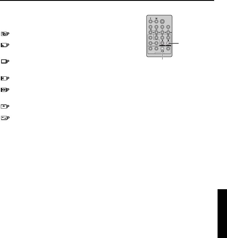
Picture Wipe And Dissolve Menu
Automatic Editing To VCR
(available only for Random Assemble Editing)
You can use not only the wipe/fader effects on page
48 but also the picture wipe and dissolve effects
below.
DISSOLVE: The new scene gradually appears
as the old one gradually disappears.
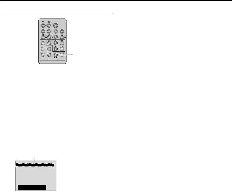
PAUSE
WIPE – CORNER: The new scene wipes in
over the previous one from the upper right corner to
the lower left corner.
WIPE – WINDOW: The next scene gradually
VCR REC STBY
wipes in from the centre of the screen toward the
13 Rewind the tape in the camcorder to the
corners, covering the previous scene.
beginning of the scene you want to edit and press
WIPE – SLIDE: The next scene gradually wipes
PAUSE (9).
in over the previous one from right to left.
14 Press VCR REC STBY (79), or manually
WIPE – DOOR: The previous scene wipes out
engage the VCR’s Record-Pause mode.
from the centre to the right and left, like a door
being pushed open to reveal the next scene.
15 Press the Recording Start/Stop Button on the
camcorder. Editing proceeds as programmed,
WIPE – SCROLL: The new scene wipes in over
right through to the end of the last registered
the last one from the bottom of the screen to the top.
scene.
WIPE – SHUTTER: The new scene wipes in
● When dubbing is complete, the camcorder
over the previous one from the centre toward the top
enters the Pause mode, and the VCR enters its
and bottom of the screen.
Record-Pause mode.
● If you do not register an Edit-Out point, the
tape will be dubbed all the way to the end
automatically.
● If you operate the camcorder during automatic
editing, the VCR will enter its Record-Pause
mode and automatic editing will stop.
16 Engage the Stop modes for the camcorder and
the VCR.
To make the R.A.Edit counter display disappear,
press R.A.EDIT ON/OFF on the remote control.
ADVANCED FEATURES
NOTES:
● Pressing R.A.EDIT ON/OFF on the remote control
clears all settings registered during Random
Assemble Editing.
● When the editing cable is connected to the remote
control’s PAUSE IN connector during dubbing,
make sure the remote control is pointed at the
VCR’s sensor, and the path between the two is
unobstructed.
● Random Assemble Editing may not function
properly when using a tape including several
duplicated time codes. (墌 pg. 21)
CONTINUED ON NEXT PAGE
Master Page: Left
GR-PD1PAL_07Advanced.fm Page 64 Thursday, June 19, 2003 2:06 PM
64 EN
USING THE REMOTE CONTROL UNIT (cont.)
For More Accurate Editing
Adjustment Of VCR/Camcorder Timing
4 Press R.A.EDIT ON/OFF to make the Random
Assemble Editing menu disappear, then press the
MENU Wheel in. The Menu Screen appears.
5 Rotate the MENU Wheel to select “t VIDEO”,
and press it. The VIDEO Menu appears.
6 Rotate the MENU Wheel to select “SYNCHRO”,
and press it. The value for “SYNCHRO” is
R.A.EDIT
ON/OFF
highlighted.
7 Based on the diagnostics performed, you can
now advance the VCR’s record timing by rotating
Some VCRs make the transition from Record-Pause
the MENU Wheel towards R. You can also delay
to Record mode faster than others. Even if you begin
the VCR’s record timing by rotating the MENU
editing for the camcorder and the VCR at exactly the
Wheel towards T.
same time, you may lose scenes you wanted, or find
The adjustment range is from –1.3 to +1.3
that you have recorded scenes you did not want. For
seconds, in 0.1-second increments.
a cleanly edited tape, confirm and adjust the timing
Press the MENU Wheel in to finish the setting.
of the camcorder against your VCR.
8 Rotate the MENU Wheel to select “BRETURN”,
Diagnosing VCR/Camcorder Timing
and press it twice.
Now perform Random Assemble Editing
1 Play back the tape in the camcorder, then point
beginning with step 6 on page 62.
the remote control at the camcorder’s remote
sensor and press R.A.EDIT ON/OFF.
NOTES:
Random Assemble Editing Menu appears.
● Before performing actual Random Assemble
Editing, do a few Random Assemble Editing trial
Program 1
runs to check whether the value you have input is
NIOUT
MOD E
appropriate or not, and make adjustments
Random Assemble
1
––
–– : –– ~
2
~
Editing Menu
accordingly.
3
~
4
~
● Depending on the recorder, there may be
5
~
6
~
situations where the timing difference cannot be
7
~
8
~
fully corrected.
CODETIME
–
–
:
––
TOTAL
0
:
000
2 Perform Random Assemble Editing on Program 1
only. In order to check VCR and camcorder
timing, select the beginning of a scene transition
as your Edit-In point.
3 Play back the dubbed scene.
● If any images from the scene prior to the
transition you chose for your Edit-In point were
recorded, that means your VCR moves too
quickly from Record-Pause to Record mode.
● If the scene you tried to dub starts in progress,
the VCR is slow to start recording.
Master Page: Right-Heading0
GR-PD1PAL.book Page 65 Tuesday, June 17, 2003 7:31 PM
SYSTEM CONNECTIONS
EN 65
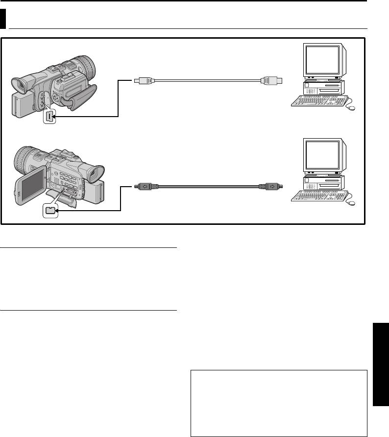
Connection To A Personal Computer
[A] Using USB cable
To USB connector
USB cable (provided)
PC
To USB
OR
[B] Using i.LINK cable
i.LINK cable
To i. LINK
(optional)
connector
PC with i.LINK
To i.LINK IN/OUT
connector
● When using an i.LINK cable, be sure to use the
[A] Using USB cable
optional JVC VC-VDV206U or VC-VDV204U
It is possible to do the following things:
i.LINK cable depending on the type of i.LINK
● Transfer still images stored on a memory card to a
connector (4 or 6 pins) on the PC.
PC.
● If the PC connected to the camcorder via the USB
● Use this camcorder as a WebCam. (墌 pg. 66)
cable is not powered, the camcorder does not
enter the USB mode.
● The date/time information cannot be captured into
[B] Using i.LINK cable
the PC.
ADVANCED FEATURES
It is also possible to transfer still/moving images to a
● Refer to the instruction manuals of the PC and
PC with an i.LINK connector by using the provided
Software.
software, software equipped with the PC or
● The still images can also be transferred to a PC
commercially available software.
with an i.LINK connector-equipped capture board.
● The system may not work properly depending on
NOTES:
the PC or capture board you are using.
● Refer to “SOFTWARE INSTALLATION AND USB/
i.LINK CONNECTION GUIDE” for the installation
“USB MODE” and/or “ACCESSING FILES”
of the bundled software and drivers.
appears on the LCD monitor while the PC is
● The software operation manual is provided as PDF
accessing data in the camcorder or the camcorder
file on the CD-ROM.
is transferring a file to the PC.
● It is recommended to use the AC Power Adapter/
NEVER disconnect the USB cable while
Charger as the power supply instead of the
“ACCESSING FILES” is displayed on the LCD
battery pack. (墌 pg. 11)
monitor since this can result in product damage.
● Never connect the USB cable and the i.LINK
cable simultaneously to the camcorder. Connect
only the cable you wish to use to the camcorder.
Master Page: Left
GR-PD1PAL.book Page 66 Tuesday, June 17, 2003 7:31 PM
66 EN
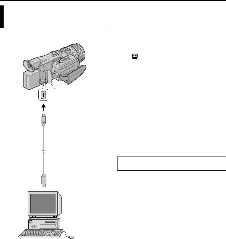
SYSTEM CONNECTIONS (cont.)
1 Make sure all necessary software (provided) are
Using The Camcorder As A
installed in your PC.
2 Set the Recording Mode Switch to “MEMORY”.
WebCam
3 Set the Power Switch to “A” or “M” while
This camcorder can be used as a WebCam via USB
pressing down the Lock Button located on the
connection.
switch.
4 Connect the camcorder to your PC using the USB
cable.
● “ ” appears on the screen.
● If the PC is not powered on, the camcorder
does not enter the Web Camera mode.
5 When finished, turn off the PC first, then the
camcorder. Disconnect the USB cable from the
camcorder and PC.
Connector Cover*
NOTES:
● It is recommended to use the AC Power Adapter/
To USB
Charger as the power supply instead of the
battery pack. (墌 pg. 11)
● You can also use the camcorder for video
conference over the Internet by using Microsoft
®
®
Windows
Messenger
. For details, refer to the
USB cable
instruction manual of the provided software.
(provided)
● In the Web Camera mode, the following buttons
cannot be operated: SNAPSHOT, INDEX, NAVI,
NAVI STORE, the Recording Start/Stop Button.
Refer to the instruction manuals of the PC and
provided Software.
To USB connector
USB-equipped PC
* When connecting the cable, open the cover.

Master Page: Left-start
GR-PD1PAL.book Page 67 Tuesday, June 17, 2003 7:31 PM
DETAILS
EN 67
ITEMS NOTES
V Power (墌 pg. 10) ● Perform charging where the temperature is between 10°C and 35°C. 20°C to 25°C
is the ideal temperature range for charging. If the environment is too cold,
charging may be incomplete.
● Charging times are for a fully discharged battery pack.
● Charging time varies according to the ambient temperature and the status of the
battery pack.
● To avoid interference with reception, do not use the AC Power Adapter/Charger
near a radio.
● Since the AC Power Adapter/Charger processes electricity internally, it becomes
warm during use. Be sure to use it only in well-ventilated areas.
V VIDEO
● When you use the LCD monitor outdoors in direct sunlight, the LCD monitor may
RECORDING
be difficult to see. If this happens, use the viewfinder instead.
(墌 pg. 18)
● The cassette holder cannot be opened unless a power supply is attached.
● There may be a delay after you open the cassette holder cover until the cassette
holder opens. Do not use force.
● Once the cassette holder is closed, it recedes automatically. Wait until it recedes
completely before closing the cassette holder cover.
● When the Recording Start/Stop button is pressed, it may take a few seconds before
actual recording starts. The “T” indicator starts rotating when the camcorder
actually starts recording.
● The time required to calculate and display the remaining tape length, and the
accuracy of the calculation, may vary according to the type of tape used.
● “TAPE END” appears when the tape reaches its end, and the power goes off
automatically if left in this condition for 5 minutes. “TAPE END” also appears
when a cassette at its end is loaded.
● During recording, sound is not heard from the speaker. To hear the sound, connect
optional headphones to the headphone connector. Adjust the sound volume by
rotating the MENU Wheel. (墌 pg. 22)
● During Interface Shooting, the “Tape Running” indicator and warning indications
(墌 pg. 73 – 75) are the only ones that are shown; they appear reversed in the
display as they would when viewing a mirror, but are not reversed in the
recording.
● The tape remaining indicator does not appear during interface shooting. However,
when the remaining time reaches 2 minutes, the indicator appears showing the
remaining time: (blinking) (blinking) (blinking)
REFERENCES

Master Page: Left-Heading0
GR-PD1PAL.book Page 68 Tuesday, June 17, 2003 7:31 PM
68 EN
TROUBLESHOOTING
If, after following the steps in the chart below, the problem still exists, please consult your nearest JVC dealer.
The camcorder is a microcomputer-controlled device. External noise and interference (from a TV, a radio,
etc.) might prevent it from functioning properly. In such cases, first disconnect its power supply unit (battery
pack, AC Power Adapter/Charger, etc.) and wait a few minutes; and then re-connect it and proceed as usual
from the beginning.
Power
SYMPTOM POSSIBLE CAUSES CORRECTIVE ACTION
1. No power is supplied. 1. •The power is not connected
1. •Connect the AC Power
properly.
Adapter/Charger securely.
•The battery is dead.
(墌 pg. 11)
•The LCD monitor is not open
•Replace the dead battery
fully or the viewfinder is not
with a fully charged one.
pulled out when recording.
(墌 pg. 10, 11)
•Open the LCD monitor fully
or pull out the viewfinder.
Video and D.S.C. Recording
SYMPTOM POSSIBLE CAUSES CORRECTIVE ACTION
2. Recording cannot be
2. •The Power Switch is set to
2. •Set the Power Switch to “A”
performed.
“P” or “OFF”.
or “M”. (墌 pg. 18, 26)
— For Video Recording —
— For Video Recording —
•The tape’s erase protection
•Set the tape’s erase
tab is set to “SAVE”.
protection tab to “REC”.
•The Recording Mode Switch
(墌 pg. 16)
is set to “MEMORY”.
•Set the Recording Mode
•“TAPE END” appears.
Switch to “VIDEO”.
•The cassette holder cover is
•Replace with new cassette.
open.
(墌 pg. 16)
— For D.S.C. Recording —
•Close the cassette holder
•The Recording Mode Switch
cover.
is not set to “MEMORY”.
— For D.S.C. Recording —
•Set the Recording Mode
Switch to “MEMORY”.
3. When shooting a subject
3. •This is a result of exceedingly
3.
illuminated by bright light,
high contrast, and is not a
—
vertical lines appear.
malfunction.
4. When the screen is under
4. •This is not a malfunction. 4.
direct sunlight during shooting,
—
the screen becomes red or
black for an instant.
5. During recording, the date/
5. •“DATE/TIME” is set to “OFF”. 5. • Set “DATE/TIME” to “ON”.
time does not appear.
(墌 pg. 33, 37)
6. During recording, sound
6. •The optional headphones are
6. •Connect the optional
cannot be heard.
not connected to the
headphones to the
headphones connector.
headphone connector.
(墌 pg. 83)

Master Page: Right
GR-PD1PAL.book Page 69 Tuesday, June 17, 2003 7:31 PM
EN 69
7. The LCD monitor or
7. •Certain Wipe/Fader effects,
7. •Re-read the sections covering
viewfinder indications blink.
certain modes of Program
Wipe/Fader effects, Program
AE, “OIS” and other
AE and “OIS”. (墌 pg. 35, 48)
functions that cannot be used
together are selected at the
same time.
8. Digital Zoom does not work. 8. •10X optical zoom is selected.
8. •Set “ZOOM” to “40X” or
•The Recording Mode Switch
“200X”. (墌 pg. 34)
is set to “MEMORY”.
•Set the Recording Mode
Switch to an appropriate
position except “MEMORY”.
Video and D.S.C. Playback
SYMPTOM POSSIBLE CAUSES CORRECTIVE ACTION
9. Play, Rewind and Fast-Forward
9. •The Power Switch is set to
9. •Set the Power Switch to
functions do not work.
“A” or “M”.
“P”. (墌 pg. 22)
•The Playback Mode Switch is
•Set the Playback Mode
set to “MEMORY”.
Switch to “VIDEO”.
10. The tape is moving, but there is
10. •Your TV has AV input
10. •Set the TV to the mode or
no picture.
terminals, but is not set to its
channel appropriate for
VIDEO mode.
video playback. (墌 pg. 24)
•The cassette holder cover is
•Close the cassette holder
open.
cover. (墌 pg. 16)
11. Blocks of noise appear during
11.
11. •Clean the video heads with
playback, or there is no
an optional cleaning
—
playback picture and the
cassette.
screen becomes blue.
12. A memory card cannot be
12. •The Power Switch is set to
12. •Set the Power Switch to
played back.
“A” or “M”.
“P”. (墌 pg. 27)
•The Playback Mode Switch is
•Set the Playback Mode
set to “VIDEO”.
Switch to “MEMORY”.
13. The image on the 4:3 TV is
13. •This occurs during recording
13. •This is not a malfunction.
elongated vertically (squeeze).
in HI-RES or PS50 mode
•Disconnect either of two
when a tape (its erase
cables.
protection tab is set to “REC”)
is loaded.
•The component video cable
and S/AV/Editing cable are
connected simultaneously.
REFERENCES
14. The screen of the LCD monitor
14. •The S/AV/Editing cable is
14. •This is not a malfunction.
or viewfinder is blackened or
connected and “S/AV
After dubbing, set “S/AV
blocks of noise appear on its
INPUT” (墌 pg. 39) is set to
INPUT” back to “OFF”.
right side when the Power
“A/V IN” or “S IN”.
Switch is set to “P” for
dubbing (but 4·9 is not
pressed).

Master Page: Left
GR-PD1PAL.book Page 70 Tuesday, June 17, 2003 7:31 PM
70 EN
TROUBLESHOOTING (cont.)
Advanced features
SYMPTOM POSSIBLE CAUSES CORRECTIVE ACTION
15. The focus does not adjust
15. •Focus is set to the Manual
15. •Set Focus to the Auto mode.
automatically.
mode.
(墌 pg. 44)
•The recording was done in a
•Clean the lens and check the
dark place, or the contrast
focus again. (墌 pg. 79)
was low.
•The lens is dirty or covered
with condensation.
16. In the 5-Second mode,
16. •The 5-Second mode is set to
16. •Set “5S” to “5S” in MANUAL
recording ends before
“Anim.” in MANUAL Menu.
Menu. (墌 pg. 33, 35)
5 seconds have elapsed.
17. Snapshot mode cannot be
17. •The Squeeze mode
17. •Disengage the Squeeze
used.
(SQUEEZE) is selected.
(SQUEEZE) mode.
(墌 pg. 33, 36)
18. The colour of Snapshot looks
18. •The light source or the
18. •Find a white subject and
strange.
subject does not include
compose your shot so that it
white. Or there are various
also appears in the frame.
different light sources behind
(墌 pg. 26, 42)
the subject.
•Disengage the Sepia (SEPIA)
•The Sepia (SEPIA) or
and Monotone
Monotone (MONOTONE)
(MONOTONE). (墌 pg. 33,
mode is activated.
49)
19. The image taken using
19. •Shooting was performed
19. •Press BACK LIGHT.
Snapshot is too dark.
under backlit conditions.
(墌 pg. 43)
20. The image taken using
20. •The subject is too bright. 20. •Press P.A E and set
Snapshot is too bright.
“PROGRAM AE” to
“SPOTLIGHT”. (墌 pg. 48)
21. White Balance cannot be
21. •The Sepia (SEPIA) or
21. •Disengage the Sepia (SEPIA)
activated.
Monotone (MONOTONE)
or Monotone (MONOTONE)
mode is activated.
mode before setting White
Balance. (墌 pg. 49)
22. Wipe/Fader effects do not
22. •The Power Switch is set to
22. •Set the Power Switch to “M”.
work.
“A”.
(墌 pg. 14)
23. The Black & White Fader does
23. •The Sepia (SEPIA) or
23. •Disengage the Sepia (SEPIA)
not work.
Monotone (MONOTONE)
and Monotone
mode is activated.
(MONOTONE).
(墌 pg. 33, 49)
24. Program AE does not work. 24. •The Power Switch is set to
24. •Set the Power Switch to “M”.
“A”.
(墌 pg. 14)
25. Cannot record signals from a
25. •The connected device is not
25. •Dubbing from other devices
device which is connected to
compatible with this
in MPEG2 format is possible
the i.LINK IN/OUT connector.
camcorder.
if the connected device is
another same model of this
unit.

Master Page: Right
GR-PD1PAL.book Page 71 Tuesday, June 17, 2003 7:31 PM
EN 71
Other problems
SYMPTOM POSSIBLE CAUSES CORRECTIVE ACTION
26. The CHARGE indicator on the
26. •The temperature of the
26. •To protect the battery, it is
AC Power Adapter/Charger
battery is extremely high/low.
recommended to charge it in
does not light.
•Charging is difficult in places
places with a temperature of
subject to extremely high/
10°C to 35°C. (墌 pg. 76)
low temperatures.
27. “SET DATE/TIME!” appears. 27. •The built-in clock’s
27. •Connect the camcorder to an
rechargeable lithium battery
AC outlet using the AC Power
is discharged.
Adapter/Charger for over 24
•The previously set date/time
hours to charge the clock’s
is erased.
lithium battery. (墌 pg. 15)
28. There is no picture. 28. •The camcorder is not getting
28. •Turn the camcorder’s power
power, or some other
off and on again. (墌 pg. 14)
malfunction exists.
29. Some functions are not
29. •The Power Switch is set to
29. •Set the Power Switch to “M”.
available using the MENU
“A”.
(墌 pg. 14)
Wheel.
30. Files stored in the memory
30. •Files stored in the memory
30. •Remove protection from the
card cannot be deleted.
card are protected.
files stored in the memory
card and delete them.
(墌 pg. 29, 30)
31. When the image is printed
31. •This is not a malfunction. 31. •By recording with “OIS”
from the printer, a black bar
activated (墌 pg. 33, 35) this
appears at the bottom of the
can be avoided.
screen.
32. When the camcorder is
32. •The i.LINK cable was
32. •Turn the camcorder’s power
connected via the i.LINK
plugged/unplugged with
off and on again, then
connector, the camcorder does
power turned on.
operate it.
not operate.
33. The rear of the LCD monitor is
33. •The light used to illuminate
33. •Close the LCD monitor to
hot.
the LCD monitor causes it to
turn it off or set the Power
become hot.
Switch to “OFF”, and let the
unit cool down.
34. Images on the LCD monitor
34. •In places subject to low
34. •Adjust the brightness and
appear dark or whitish.
temperature, images become
angle of the LCD monitor.
dark due to the
(墌 pg. 12, 13)
characteristics of the LCD
REFERENCES
monitor. When this happens,
the displayed colours differ
from those that are actually
recorded. This is not a defect
of the camcorder.
•When the LCD monitor’s
fluorescent light reaches the
end of its service life, images
on the LCD monitor become
dark. Consult your nearest
JVC dealer.
CONTINUED ON NEXT PAGE

Master Page: Left
GR-PD1PAL.book Page 72 Tuesday, June 17, 2003 7:31 PM
72 EN
TROUBLESHOOTING (cont.)
35. Coloured bright spots appear
35. •The LCD monitor and the
35.
all over the LCD monitor or the
viewfinder are made with
viewfinder.
high-precision technology.
However, black spots or
bright spots of light (red,
green or blue) may appear
constantly on the LCD
—
monitor or the viewfinder.
These spots are not recorded
on the tape. This is not due to
any defect of the unit.
(Effective dots: more than
99.99 %)
36. The indicators and the image
36. •This may occur when the
36.
colour on the LCD monitor are
surface or the edge of the
—
not clear.
LCD monitor is pressed.
37. The cassette will not load
37. •The battery’s charge is low. 37. •Install a fully charged battery.
properly.
(墌 pg. 10, 11)
38. The memory card cannot be
38.
38. •Push in the memory card a
—
removed from the camcorder.
few more times. (墌 pg. 17)
39. Picture does not appear on the
39. •The viewfinder is pulled out
39. •Push the viewfinder back in
LCD monitor.
and “PRIORITY” is set to
or set “PRIORITY” to “LCD”
“FINDER”.
or “BOTH”.
•The LCD monitor’s brightness
(墌 pg. 12, 33, 36)
setting is too dark.
•Adjust the brightness of the
LCD monitor. (墌 pg. 13)
•If the monitor is tilted
upward 180 degrees, open
the monitor fully. (墌 pg. 12)
40. Images on the LCD monitor
40. •The speaker volume is too
40. •Turn the speaker volume
are jittery.
great.
down. (墌 pg. 22)
41. The LCD monitor, the
41.
41. •Wipe them gently with soft
viewfinder and the lens have
cloth. Wiping strongly can
become dirty (ex. fingerprints).
cause damage. (墌 pg. 79) To
—
clean the viewfinder, please
consult your nearest JVC
dealer.
42. Time code does not appear. 42. •“TIME CODE” is set to
42. •Set “TIME CODE” to “ON”.
“OFF”.
(墌 pg. 33, 37, 40)
43. An error indication (E01, E02
43. •A malfunction of some kind
43. •墌 pg. 75.
or E06) appears.
has occurred. In this case the
camcorder’s functions
become unusable.
44. An error indication (E03 or
44. •A malfunction of some kind
44. •墌 pg. 75.
E04) appears.
has occurred. In this case the
camcorder’s functions
become unusable.
45. The remote control does not
45. •“REMOTE” is set to “OFF”.
45. •Set “REMOTE” to “ON”.
work.
•The remote control does not
(墌 pg. 33, 36)
point at the remote sensor.
•Point at the remote sensor.
•The remote control batteries
(墌 pg. 56)
are exhausted.
•Replace the batteries with
fresh ones. (墌 pg. 56)
Master Page: Right
GR-PD1PAL.book Page 73 Tuesday, June 17, 2003 7:31 PM
EN 73
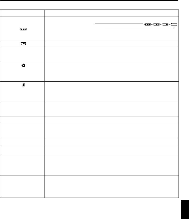
Warning Indications
Indications Meaning
Displays the battery remaining power.
Remaining power level: high
Remaining power level: exhausted
As the battery power comes close to nil, the battery indicator blinks.
When the battery power is exhausted, power turns off automatically.
Appears when no tape is loaded. (墌 pg. 16)
Appears when the erase protection tab is set to “SAVE” while the Power Switch is
CHECK TAPE’S ERASE
set to “A” or “M” and the Recording Mode Switch is set to any mode except
PROTECTION TAB
“MEMORY”. (墌 pg. 14)
Appears if dirt is detected on the heads during recording. Use an optional
HEAD CLEANING
cleaning cassette.
REQUIRED USE
CLEANING CASSETTE
Appears if condensation occurs. When this indication is displayed, wait more
CONDENSATION
than 1 hour until condensation disappears.
OPERATION PAUSED
PLEASE WAIT
Appears if a tape is not loaded when the Recording Start/Stop Button or
TAPE!
SNAPSHOT Button is pressed while the Power Switch is set to “A” or “M” and
the Recording Mode Switch is set to any mode except “MEMORY”.
TAPE END Appears when the tape ends during recording or playback. (墌 pg. 67)
● Appears when the date/time is not set. (墌 pg. 15)
SET DATE/TIME!
● Appears when the built-in clock (lithium) battery is discharged and the
previously set date/time is erased. (墌 pg. 15)
LENS CAP Appears for 5 seconds after power is turned on if the lens cap is attached.
CAN NOT PLAY BACK
Appears when you attempt to play back a tape that is not compatible with this
THIS TAPE
camcorder.
CAN NOT CHANGE
Appears when you attempt to change the recording mode during recording.
RECORDING MODE
(墌 pg. 19)
RECORDING IS
STOPPED
INVALID DATA!
Appears when you attempt to record signals which are copygurded or not
CAN NOT RECORD
compatible with this camcorder.
COPY PROTECTED
CAN NOT RECORD
REFERENCES
CONTINUED ON NEXT PAGE

Master Page: Left
GR-PD1PAL.book Page 74 Tuesday, June 17, 2003 7:31 PM
74 EN
TROUBLESHOOTING (cont.)
Warning Indications
Indications Meaning
CAN NOT DISPLAY
Appears when dubbing a scene recorded in HI-RES mode through the
ON LCD MONITOR
component video connectors. (墌 pg. 53)
AND VIEWFINDER
IN THIS MODE
i.LINK CONNECTION
Appears when an i.LINK cable is connected but not detected. Disconnect the
ERROR! CHECK
cable once and connect it again, or disconnect other connected cables.
CABLE CONNECTION
(墌 pg. 53)
TO CHANGE i.LINK
Appears when you attempt to change the i.LINK output mode while an i.LINK
OUTPUT SETTING,
cable is connected. (墌 pg. 53)
DISCONNECT i.LINK
CABLE, FIRST
INVALID DATA!
Appears when you attempt to dub signals which are copygurded or not
CAN NOT INPUT
compatible with this camcorder through an i.LINK cable.
COPY PROTECTED
CAN NOT INPUT
CAN NOT DECODE
VIDEO OR AUDIO
A. DUB ERROR! Appears if Audio Dubbing is attempted on a blank portion of a tape. (墌 pg. 58)
A. DUB ERROR!
● Appears if Audio Dubbing is attempted on a tape recorded in PS50 or HI-RES
<MPEG2 RECORDED>
mode.
<CANNOT DUB ON A
(墌 pg. 58)
LP RECORDED TAPE>
● Appears if Audio Dubbing is attempted on a tape recorded in the LP mode.
<CANNOT DUB ON A
(墌 pg. 58)
16bit RECORDING>
● Appears if Audio Dubbing is attempted on a tape recorded in 16-bit audio.
<CHECK TAPE’S
(墌 pg. 58)
ERASE PROTECTION
● Appears if A. DUB (D) on the remote control is pressed when the erase
TAB>
protection tab is set to “SAVE”. (墌 pg. 58)
INSERT ERROR! Appears if Insert Editing is attempted on a blank portion of a tape. (墌 pg. 59)
INSERT ERROR!
● Appears if Insert Editing is attempted on a tape recorded in PS50 or HI-RES
<MPEG2 RECORDED>
mode.
<CANNOT EDIT ON A
(墌 pg. 59)
LP RECORDED TAPE>
● Appears if Insert Editing is attempted on a tape recorded in the LP mode.
<CHECK TAPE’S
(墌 pg. 59)
ERASE PROTECTION
● Appears if INSERT (I) on the remote control is pressed when the erase
TAB>
protection tab is set to “SAVE”. (墌 pg. 59)
<CHANGE REC. MODE
TO DV>
CAN NOT R.A.E.
Appears if Random Assemble Editing is attempted on a tape recorded in PS50 or
THIS TAPE
HI-RES mode. (墌 pg. 60)

Master Page: Right
GR-PD1PAL.book Page 75 Tuesday, June 17, 2003 7:31 PM
EN 75
Warning Indications
Indications Meaning
MEMORY IS FULL Appears when the memory card’s memory is full and shooting is not possible.
● Appears if dubbing of copyguarded signals is attempted while this camcorder is
being used as a recorder.
● Appears in the following cases when dubbing still images from a tape to a
memory card:
COPYING FAILED
– when no memory card is loaded.
– when the memory card’s memory is full.
– when the memory card is not formatted.
– when a write-protected SD Memory Card is loaded. (墌 pg. 55)
Appears if there is no memory card loaded when you attempt to record on a
MEMORY CARD!
memory card or access data on a memory card.
Appears when there is a problem with a memory card and its memory is corrupt,
PLEASE FORMAT
or it has not been initialised. Initialise the memory card. (墌 pg. 32)
Appears if there are no image files stored in the memory card when you attempt
NO IMAGES STORED
memory card playback.
Appears when the camcorder does not recognise the loaded memory card.
Remove the memory card once and insert it again. Repeat these procedures until
CARD ERROR!
no indication appears. If the indication still appears, the memory card is
corrupted.
Appears when playing back a file that is not compatible with DCF or a file with a
UNSUPPORTED FILE!
size that is not compatible with this camcorder.
● Appears when you attempt to shoot digital still images when the write
CHECK CARD’S WRITE
protection tab on the SD Memory Card is set to the “LOCK” position.
PROTECTION SWITCH
● Appears when you attempt MEMORY SELECT menu operation with a write-
protected SD Memory Card loaded.
The error indications (E01, E02 or E06) show what type of malfunction has
E01, E02 or E06
occurred. When an error indication appears, the camcorder turns off
UNIT IN SAFEGUARD
automatically. Remove the power supply (battery, etc.) and wait a few minutes for
MODE REMOVE AND
the indication to clear. When it does, you can resume using the camcorder. If the
REATTACH BATTERY
indication remains, consult your nearest JVC dealer.
The error indications (E03 or E04) show what type of malfunction has occurred.
E03 or E04
When an error indication appears, the camcorder turns off automatically. Eject
UNIT IN SAFEGUARD
the cassette once and re-insert it, then check if the indication clears. When it
MODE EJECT AND
does, you can resume using the camcorder. If the indication remains, consult
REINSERT TAPE
your nearest JVC dealer.
REFERENCES
Master Page: Left-Heading0
GR-PD1PAL.book Page 76 Tuesday, June 17, 2003 7:31 PM
76 EN
CAUTIONS
General Battery Precautions
NOTES:
● It is normal for the battery pack to be warm after
If the remote control is not functioning even if it is
charging, or after use.
being operated correctly, the batteries are
Temperature Range Specifications
exhausted. Replace them with fresh ones.
Charging........10°C to 35°C
Use only the following batteries: AAA (R03) size x 2
Operation ......0°C to 40°C
Storage ..........–20°C to 50°C
Please make note of the following rules for battery
● Recharging time is based on room temperature of
use. When misused, the batteries can leak or
20°C.
explode.
● The lower the temperature, the longer recharging
1. When replacing batteries, refer to page 56.
takes.
2. Do not use any different size of batteries from
those specified.
3. Be sure to install batteries in the correct
Cassettes
direction.
To properly use and store your cassettes, be sure to
4. Do not use rechargeable batteries.
read the following cautions:
5. Do not expose the batteries to excessive heat as
1. During use…
they can leak or explode.
... make sure the cassette bears the Mini DV
6. Do not dispose of the batteries in a fire.
mark.
7. Remove the batteries from the unit if it is to be
... be aware that recording onto prerecorded
stored for an extended period to avoid battery
tapes automatically erases the previously
leakage which can cause malfunctions.
recorded video and audio signals.
8. Do not recharge the provided batteries.
... make sure the cassette is positioned properly
when inserting.
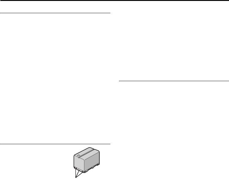
Battery Packs
... do not load and unload the cassette
repeatedly without allowing the tape to run at
The supplied battery pack
all. This slackens the tape and can result in
is a lithium-ion battery.
damage.
Before using the supplied
... do not open the front tape cover. This exposes
battery pack or an
the tape to fingerprints and dust.
optional battery pack, be
2. Store cassettes…
sure to read the following
Terminals
... away from heaters or other heat sources.
cautions:
... out of direct sunlight.
1. To avoid hazards…
... where they won’t be subject to unnecessary
... do not burn.
shock or vibration.
... do not short-circuit the terminals. When
... where they won’t be exposed to strong
transporting, make sure the provided battery
magnetic fields (such as those generated by
cap is attached to the battery. If the battery cap
motors, transformers or magnets).
is misplaced, carry the battery in a plastic bag.
... vertically, in their original cases.
... do not modify or disassemble.
... do not expose the battery to temperatures
exceeding 60°C, as this may cause the battery
to overheat, explode or catch fire.
... use only specified chargers.
2. To prevent damage and prolong service life…
... do not subject to unnecessary shock.
... charge in an environment where temperatures
are within the tolerances shown in the chart
below. This is a chemical reaction type
battery — cooler temperatures impede
chemical reaction, while warmer
temperatures can prevent complete charging.
... store in a cool, dry place. Extended exposure
to high temperatures will increase natural
discharge and shorten service life.
... fully charge and then fully discharge the
battery every 6 months when storing the
battery pack over a long period time.
... remove from charger or powered unit when
not in use, as some machines use current even
when switched off.

Master Page: Right
GR-PD1PAL.book Page 77 Tuesday, June 17, 2003 7:31 PM
EN 77
... in places subject to excessive shock or
Memory Cards
vibration.
To properly use and store your memory cards, be
... near a television set.
sure to read the following cautions:
... near appliances generating strong magnetic or
1. During use…
electric fields (speakers, broadcasting
... make sure the memory card bears the SD or
antennas, etc.).
MultiMediaCard mark.
... in places subject to extremely high (over
... make sure the memory card is positioned
40°C) or extremely low (under 0°C)
properly when inserting.
temperatures.
2. While the memory card is being accessed
3. DO NOT leave the unit…
(during recording, playback, deletion,
... in places of over 50°C.
initialisation, etc.)…
... in places where humidity is extremely low
... never unload the memory card and never turn
(below 35%) or extremely high (above 80%).
off the camcorder.
... in direct sunlight.
3. Store memory cards…
... in a closed car in summer.
... away from heaters or other heat sources.
... near a heater.
... out of direct sunlight.
4. To protect the unit, DO NOT…
... where they won’t be subject to unnecessary
... allow it to become wet.
shock or vibration.
... drop the unit or strike it against hard objects.
... where they won’t be exposed to strong
... subject it to shock or excessive vibration
magnetic fields (such as those generated by
during transportation.
motors, transformers or magnets).
... keep the lens directed at extremely bright
objects for long periods.
... expose the lens and viewfinder’s lens to direct
LCD Monitor
sunlight.
1. To prevent damage to the LCD monitor,
... carry it by holding the LCD monitor or the
DO NOT…
viewfinder.
... push it strongly or apply any shocks.
... swing it excessively when using the hand strap
... place the camcorder with the LCD monitor on
or the grip.
the bottom.
... swing the soft camera case excessively when
2. To prolong service life…
the camcorder is inside it.
... avoid rubbing it with coarse cloth.
3. Be aware of the following phenomena for LCD
monitor use.
These are not malfunctions:
•While using the camcorder, the surface around
the LCD monitor and/or the back of the LCD
monitor may heat up.
•If you leave power on for a long time, the
surface around the LCD monitor becomes hot.
Main Unit
1. For safety, DO NOT…
... open the camcorder’s chassis.
REFERENCES
... disassemble or modify the unit.
... short-circuit the terminals of the battery pack.
Keep it away from metallic objects when not
in use.
... allow inflammables, water or metallic objects
to enter the unit.
... remove the battery pack or disconnect the
power supply while the power is on.
... leave the battery pack attached when the
camcorder is not in use.
2. Avoid using the unit…
... in places subject to excessive humidity or
dust.
... in places subject to soot or steam such as near
a cooking stove.
CONTINUED ON NEXT PAGE
Master Page: Left
GR-PD1PAL.book Page 78 Tuesday, June 17, 2003 7:31 PM
78 EN
CAUTIONS (cont.)
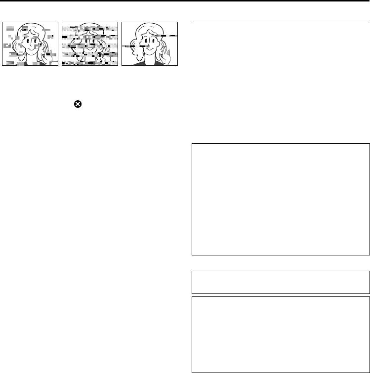
5. Dirty heads can cause the following problems:
How To Handle A CD-ROM
•Take care not to soil or scratch the mirror surface
(opposite to the printed surface). Do not write
anything or put a sticker on either the front or back
surface. If the CD-ROM gets dirty, gently wipe it
with a soft cloth outward from the centre hole
using a circular motion.
•No picture during playback.
•Do not use conventional disc cleaners or cleaning
•Blocks of noise appear during playback.
spray.
•During recording or playback, the Head Clog
•Do not bend the CD-ROM or touch its mirror
Warning indicator “ ” appears.
surface.
•Recording cannot be performed properly.
•Do not store your CD-ROM in a dusty, hot or
In such cases, use the provided cleaning cassette.
humid environment. Keep it away from direct
Insert it and play back. If the cassette is used more
sunlight.
than once consecutively, damage to the video heads
may result. After the camcorder plays back for about
About moisture condensation...
20 seconds, it stops automatically. Also refer to the
● You have observed that pouring a cold liquid
cleaning cassette’s instructions.
into a glass will cause drops of water to form on
If, after using the cleaning cassette, the problems still
the glass’ outer surface. This same phenomenon
exist, consult your nearest JVC dealer.
occurs on the head drum of a camcorder when
Mechanical moving parts used to move the video
it is moved from a cool place to a warm place,
heads and video tape tend to become dirty and
after heating a cold room, under extremely
worn out over time. In order to maintain a clear
humid conditions or in a place directly
picture at all times, periodic check-ups are
subjected to the cool air from an air conditioner.
recommended after using the unit for about 1,000
● Moisture on the head drum can cause severe
hours. For periodic check-ups please consult your
damage to the video tape, and can lead to
nearest JVC dealer.
internal damage to the camcorder itself.
Serious malfunctioning
If malfunctioning occurs, stop using the unit
immediately and consult your local JVC dealer.
The camcorder is a microcomputer-controlled
device. External noise and interference (from a TV,
a radio, etc.) might prevent it from functioning
properly. In such cases, first disconnect its power
supply unit (battery pack, AC Power Adapter/
Charger, etc.) and wait a few minutes and then re-
connect it and proceed as usual from the
beginning.
Master Page: Right-Heading0
GR-PD1PAL.book Page 79 Tuesday, June 17, 2003 7:31 PM
USER MAINTENANCE
EN 79
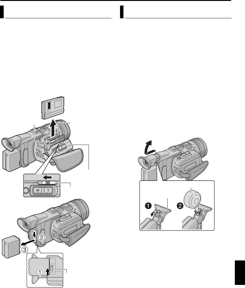
After Use
Cleaning The Camcorder
1 Turn off the camcorder.
1 To clean the exterior, wipe gently with a soft
cloth.
2 Loosen the grip strap.
Put the cloth in diluted mild soap and wring it
3 Slide and hold OPEN/EJECT in the direction of
well to wipe off heavy dirt. Then wipe again with
the arrow, then pull the cassette holder cover
a dry cloth.
open until it locks. The cassette holder opens
2 Press PUSH OPEN and open the LCD monitor.
automatically. Remove the cassette.
Wipe gently with a soft cloth. Be careful not to
4 Press “PUSH HERE” to close the cassette holder.
damage the monitor. Close the LCD monitor.
● Once the cassette holder is closed, it recedes
3 To clean the lens, blow it with a blower brush,
automatically. Wait until it recedes completely
then wipe gently with lens cleaning paper.
before closing the cassette holder cover.
4 To clean the viewfinder, raise the viewfinder to
5 Slide BATT.RELEASE 1 and remove the battery
the vertical position.
pack 2 3.
5 Open the viewfinder cleaning hatch in the
Remove.
direction of the arrow A.
Insert a lens blower or soft cloth into the gap at
the bottom of the viewfinder and clean the
PUSH HERE
interior of the viewfinder with it B.
Cassette holder
6 Close the hatch. Tilt the viewfinder back to the
horizontal position and push it back in.
Cassette holder
cover
Lens blower
OPEN/EJECT Switch
Hatch
NOTES:
● Avoid using strong cleaning agents such as
benzine or alcohol.
● Cleaning should be done only after the battery
REFERENCES
pack has been removed or other power units have
been disconnected.
● Mould may form if the lens is left dirty.
BATT.RELEASE Switch
● When using a cleaner or chemically treated cloth
refer to the cautions of each product.

Master Page: Left-Heading0
GR-PD1PAL.book Page 80 Tuesday, June 17, 2003 7:31 PM
80 EN
SPECIFICATIONS
Camcorder
For General
Power supply : DC 6.3 V (Using AC Power Adapter/Charger)
DC 7.2 V (Using battery pack)
Power consumption
LCD monitor off, viewfinder on : Approx. 6.8 W (DV)/8.0 W (HI-RES, PS50)
LCD monitor on, viewfinder off : Approx. 8.5 W (DV)/9.7 W (HI-RES, PS50)
Dimensions (W x H x D) : 114.5 mm x 99 mm x 271.5 mm
(with the LCD monitor closed and the viewfinder pushed back in)
Weight : Approx. 1270 g
(without cassette, memory card and battery)
Approx. 1490 g
(incl. cassette, memory card and battery)
Operating temperature : 0°C to 40°C
Operating humidity : 35% to 80%
Storage temperature : –20°C to 50°C
Pickup : 1/3" CCD
Lens : F 1.8, f = 5.2 mm to 52 mm, 10:1 power zoom lens
Filter diameter : ø52 mm
LCD monitor : 3.5" diagonally measured, LCD panel/TFT active matrix system
Viewfinder : Electronic viewfinder with 0.44" colour LCD
Speaker : Monaural
For Digital Video Camera
Signal format : PAL standard
Cassette : Mini DV cassette
Tape speed : SP: 18.8 mm/s
LP: 12.5 mm/s
Maximum recording time
: SP: 80 min.
(using 80 min. cassette)
LP: 120 min.
For Digital Still Camera
Storage media : SD Memory Card/MultiMediaCard
Compression system : JPEG (compatible)
File size : 2 modes (1280 x 960 pixels/640 x 480 pixels)
Picture quality : 2 modes (FINE/STANDARD)
Approximate number of storable images
: 墌 pg. 38


