Ariston CE6VM3 R/HA: I n s t a ll a t i on
I n s t a ll a t i on: Ariston CE6VM3 R/HA
14
GB
B
efore operating your new appliance please read
this instruction booklet carefully. It contains
important information concerning the safe installation
and operation of the appliance.
Please keep these operating instructions for future
reference. Make sure that the instructions are kept
with the appliance if it is sold, given away or moved.
The appliance must be installed by a qualified
professional in accordance with the instructions
provided.
Any necessary adjustment or maintenance must be
performed after the cooker has been disconnected
from the electricity supply.
P
os
i
t
i
on
i
n
g
a
n
d
le
v
ell
i
n
g
It is possible to install the appliance alongside
cupboards whose height does not e
x
ceed that of the
hob surface.
Make sure that the wall in contact with the back of
the appliance is made from a non-flammable, heat-
resistant material (T 90°C).
To install the appliance correctly:
Place it in the kitchen, the dining room or the bed-
sit (not in the bathroom).
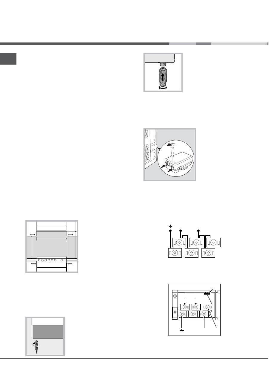
If the top of the hob is higher than the cupboards,
the appliance must be installed at least 600 mm
away from them.
If the cooker is
installed underneath a
wall cabinet, there must
be a minimum distance
of 420 mm between
this cabinet and the top
of the hob.
This distance should
be increased to 700
mm if the wall cabinets
are flammable (
see figure
).
D
o not position blinds behind the cooker or less
than 200 mm away from its sides.
Any hoods must be installed according to the
instructions listed in the relevant operating
manual.
L
e
v
ellin
g
If it is necessary to level the
appliance, screw the
adjustable feet into the places
provided on each corner of the
base of the cooker (
see
figure
).
The legs* fit into the slots on
the underside of the base of
the cooker.
Ele
c
t
r
i
c
a
l
c
onne
c
t
i
on
F
i
tt
i
n
g
t
h
e
p
o
w
e
r
s
upp
l
y c
a
b
le
To open the terminal board:
Insert a screwdriver into the side tabs of the
terminal board cover.
Pull the cover to
open it.
To install the cable, follow the instructions below:
Loosen the cable clamp screw and the wire
contact screws.
The jumpers are pre-set at the Factory for 230 V
single-phase connection (
see figure
).
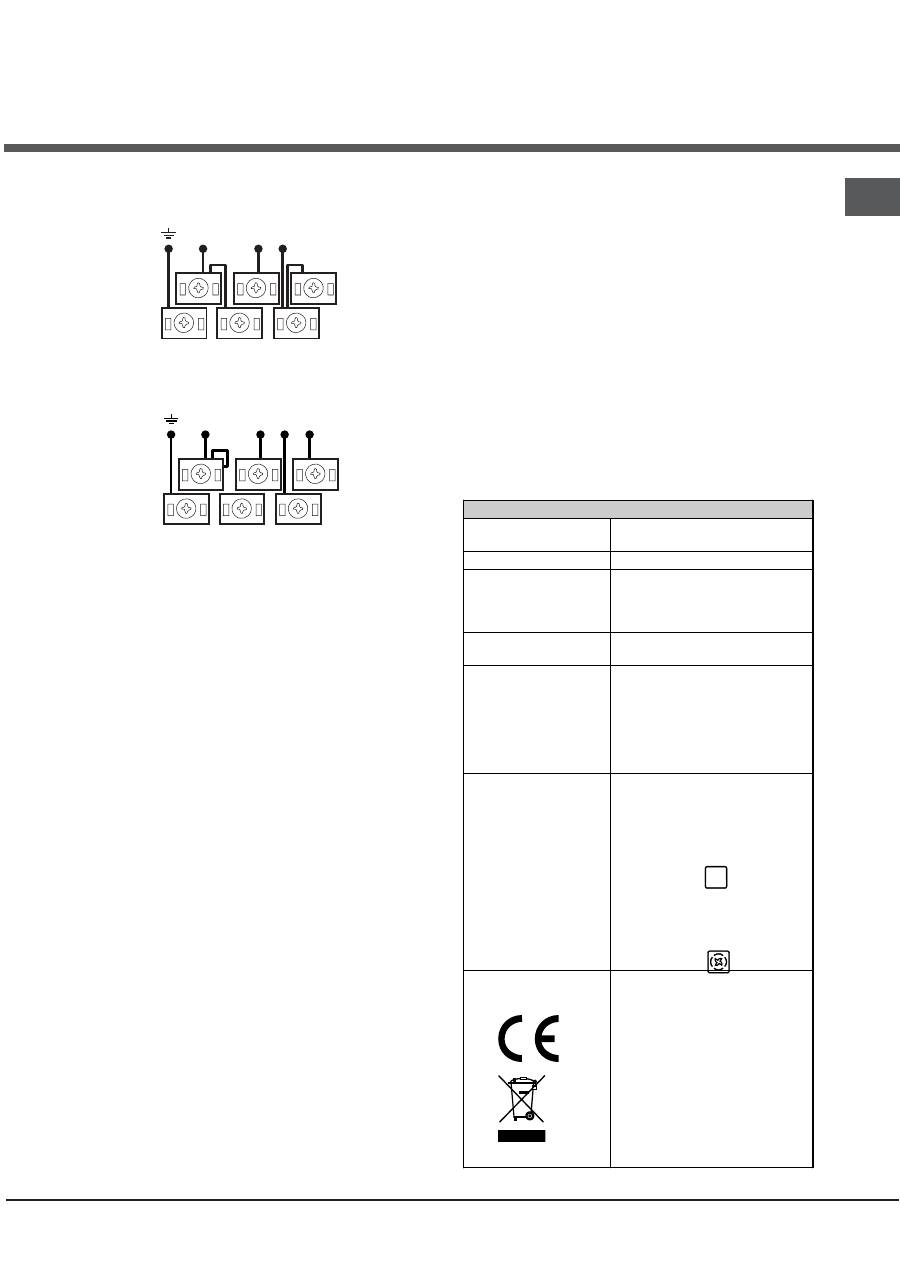
To carry out the electrical connections as shown in
the figures, use the two jumpers inside the bo
x
(
see figure
- labelled P).
I n s t a ll a t i on
HOOD
420
Min.
min.
650
mm. with hood
min.
700
mm. without hood
mm.
600
Min.
mm.
420
Min.
mm.
*
Onl
y
available
in
certain
models
.
N
L2
L1
L3
P
N
L
230V ~
H05RR-F 3x4 CEI-UNEL 35363
1
3
2
4
5
We recommend cleaning the oven before
using it for the first time, following the
instructions provided in the "Care and
maintenance" section.
GB
1
5
N
L3
L1
L2
400V 3N~
H05RR-F 5x2.5 CEI-UNEL 35363
1
3
2
4
5
N
L2 L1
400V 2N~
H05RR-F 4x4 CEI-UNEL 35363
1
3
2
4
5
Secure the power supply cable by fastening the
cable clamp screw then put the cover back on.
C
onnectin
g
t
h
e
s
upp
l
y
ca
b
le
to
t
h
e
electricit
y
mains
Install a standardised plug corresponding to the
load indicated on the appliance data plate (
see
Technical data table
).
The appliance must be directly connected to the
mains using an omnipolar switch with a minimum
contact opening of 3 mm installed between the
appliance and the mains. The switch must be
suitable for the charge indicated and must comply
with current electrical regulations (the earthing wire
must not be interrupted by the switch). The supply
cable must be positioned so that it does not come
into contact with temperatures higher than 50°C at
any point.
B
efore connecting the appliance to the power
supply, make sure that:
The appliance is earthed and the plug is compliant
with the law.
The socket can withstand the ma
x
imum power of
the appliance, which is indicated by the data
plate.
The voltage is in the range between the values
indicated on the data plate.
The socket is compatible with the plug of the
appliance. If the socket is incompatible with the
plug, ask an authorised technician to replace it.
D
o not use e
x
tension cords or multiple sockets.
O
nce the appliance has been installed, the power
supply cable and the electrical socket must be
easily accessible.
The cable must not be bent or compressed.
The cable must be checked regularly and replaced
by authorised technicians only.
T
h
e
man
u
f
act
u
rer
d
eclines
an
y
lia
b
ilit
y
s
h
o
u
l
d
t
h
ese
sa
f
et
y
meas
u
res
not
b
e
o
b
ser
v
e
d
.
TABLE OF CHARACTERISTICS
Oven dimensions
(HxWxD)
32x43.5x40 cm
Volume
56 l
Useful
measurements
relating to the oven
compartment
width 42 cm
depth 44 cm
height 8.5 cm
Voltage and
frequency
see data plate
Ceramic hob
Front Left
Back Left
Back Right
Front Right
Max. ceramic hob
consumption
1700 W
1200 W
2100 W
1200 W
6200 W
ENERGY LABEL
Directive 2002/40/EC on the
label of electric ovens.
Standard EN 50304
Natural convection energy
consumption
heating mode:
Traditional mode
Declared forced convection
energy consumption
heating mode:
Multilevel.
This appliance conforms to the
following European Economic
Community directives:
2006/95/EC dated 12/12/06
(Low Voltage) and subsequent
amendments - 2004/108/EC
dated 15/12/04
(Electromagnetic Compatibility)
and subsequent amendments -
93/68/EEC dated 22/07/93 and
subsequent amendments.
2002/96/EC
1275/2008 (Stand-by/Off mode)
Оглавление
- I n s t allazione
- D escrizione dellapparecchio
- Avv io e u t ilizzo
- T i m e r a n a lo g i c o
- U t ilizzo d el piano c o tt u r a v e tr o c e r a mica
- P reca u zioni e consigli
- Ma n u t enz i one e c u r a
- A ssistenza
- Op e r a t i n g I n s tr uc t i on s
- I n s t a ll a t i on
- D escri p tion o f t h e a pp liance
- S t a rt - up a n d u s e
- A n a lo gu e t i m e r
- U s i n g t h e g l a ss c e r ami c h o b
- P r e ca u t ions a nd t ips
- C a r e a n d mai n t en a n c e
- Ð óê îâîäñòâî ïî ýêñïëóàòàöèè
- Ì îí ò à æ
- Î ï èñàíè å èçäåëèÿ
- Âêëþ÷åíèå è ýêñïëóàòàöèÿ
- À íàë î ã î âûé òàé ì åð
- Ñ òåêë î êåðà ì è÷åñêàÿ âàð î ÷íàÿ ïàíåëü
- Ïðåä î ñò î ð î æí î ñòè è ðåê î ì åíäàöèè
- Ò å õ íè÷åñê î å î áñëóæèâàíèå è ó õ î ä
- H asználati ú tm u tató
- Ü ze mb e h el y ezés
- A k ész ü lé k le í r á sa
- B e k a pc s o l á s és h asz n á lat
- An al ó g i d õ z í tés
- A z ü v eg k er á m i a fõ z õ la p h asz n á lata
- Óv in téz k e d ése k és ta n á c s ok
- K ar b a n tart á s és á p o l á s
- Instrukcja obs∏ugi
- Instalacja
- Opis kuchni
- Uruchomienie i obs∏uga kuchni
- Analogowy minutnik
- Uruchomienie i obs∏ugap∏yty ceramicznej
- Ârodki ostro˝noÊci i porady
- Konserwacja i czyszczeniekuchni serwis
- Ïäçãßåò ÷ñÞóçò
- ÅãêáôÜóôáóç
- ÐåñéãñáöÞ ôçò óõóêåõÞò
- Åêêßíçóç êáé ÷ñÞóç
- Timer áíáëïãéêü
- ×ñÞóç ôçò õáëïêåñáìéêÞòåðéöÜíåéáò ìáãåéñÝìáôïò
- ÐñïöõëÜîåéò êáéóõìâïõëÝò
- ÓõíôÞñçóç êáé öñïíôßäá
