Sony BRAVIA KDL-26P25: Viewing pictures from connected equipment
Viewing pictures from connected equipment: Sony BRAVIA KDL-26P25
Table of contents
- Trademark information Introduction Notice for Digital TV function
- Table of Contents
- Start-up Guide 1: Checking the 2: Connecting an aerial/ accessories VCR
- 3: Bundling the cables 4: Preventing the TV from toppling over 5: Selecting the language and country/region
- 6: Auto-tuning the TV
- Safety information
- GB
- GB
- Precautions Disposal of the TV set
- Overview of the remote
- Overview of the TV buttons and indicators Watching TV
- Additional operations To access Text Picture Freeze PIP in PC Mode (Picture in Picture)
- Checking the Digital Electronic Programme Guide (EPG)
- Using the Favourite list
- Navigating through menus
- Picture Adjustment menu
- Sound Adjustment menu
- Features menu
- Set-up menu
- Sound Offset Manual Programme Preset
- Digital Set-up menu
- Using Optional Equipment Connecting optional equipment Connecting to the TV (side)
- Connecting to the TV (rear)
- Viewing pictures from connected equipment
- Additional Information Specifications
- Troubleshooting Picture Problem Cause/Remedy
- Problem Cause/Remedy Sound Channels General
010COV.book Page 25 Friday, January 19, 2007 9:53 AM
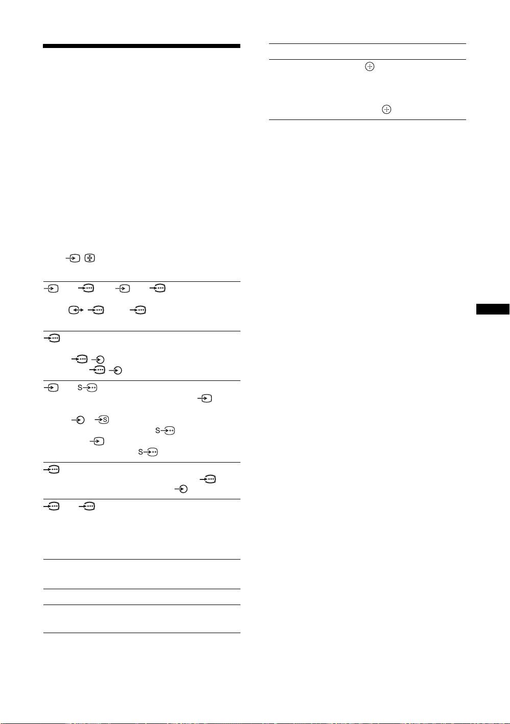
To Do this
Viewing pictures from
Access the Input
Press to access the Input signal
signal index table
index table. (Then, only in
analogue mode, press
g.) To
connected equipment
select an input source, press
F/f,
then press .
Switch on the connected equipment, then
perform one of the following operation.
For equipment connected to the scart sockets using a
fully-wired 21-pin scart lead
Start playback on the connected equipment.
The picture from the connected equipment appears on
the screen.
For an auto-tuned VCR (page 4)
In analogue mode, press PROG +/-, or the number
buttons, to select the video channel.
For other connected equipment
Press / repeatedly until the correct input
symbol (see below) appears on the screen.
AV1/ AV1, AV2/ AV2:
Audio/video or RGB input signal through the scart
socket / 1 or 2. appears only if an RGB
source has been connected.
Using Optional Equipment
AV 3:
Component input signal through the Y, P
B/CB, PR/CR
sockets / 3, and audio input signal through the
L, R sockets / 3.
AV 4/ AV 4:
Video input signal through the video socket 4, and
audio input signal through the L (MONO), R audio
sockets 4. appears only if the equipment is
connected to the S video socket 4 instead of the
video socket 4, and S video input signal is input
through the S video socket 4.
5:
RGB input signal through the PC connectors 5, and
audio input signal through the socket .
AV6/ AV7:
Digital audio/video signal is input through the HDMI IN
6, 7 socket. Audio input signal is analogue only if the
equipment has been connected using the DVI and audio
out socket.
Additional operations
To Do this
Return to the normal
Press DIGITAL or ANALOG.
TV operation
GB
25
KDL-40/32/26U2000
2-693-044-41(0)
