Sony SDM-X75KB – page 3
Manual for Sony SDM-X75KB
Table of contents
17
GB
p y
AEP.fm
Reducing the power consumption
(ECO mode)
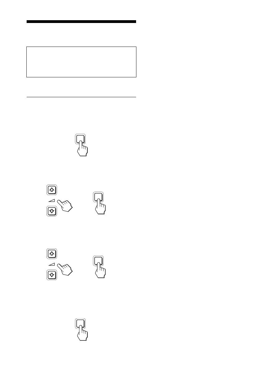
If you press the ECO button on the front of the display repeatedly,
you can select the screen brightness.
Each mode appears on the screen and the screen brightness is
reduced according to the mode. The menu automatically
disappears after about 5 seconds.
Screen brightness and power consumption are reduced as the
mode changes from HIGH to MIDDLE to LOW.
The default setting of the screen brightness is set to HIGH.
Automatic brightness adjustment
function (light sensor)
This display is provided with a feature to automatically adjust the
screen brightness according to the brightness of the surroundings.
The brightness of the screen is set to the most appropriate level by
setting the ECO mode to AUTO with the ECO button on the front
of the display, or in the PICTURE ADJUST menu. The default
setting of the brightness of the screen is set to HIGH. Also, when
you set the ECO mode to “AUTO” with the ECO button on the
front of the display, the adjustment bar is also displayed. You can
adjust the bar with the
m
/
M
buttons. Screen brightness changes
according to the level you set.
Automatic picture quality
adjustment function (analog RGB
signal only)
When the display receives an input signal, it
automatically adjusts the picture’s position and
sharpness (phase/pitch), and ensures that a clear
picture appears on the screen.
The factory preset mode
When the display receives an input signal, it automatically
matches the signal to one of the factory preset modes stored in the
display’s memory to provide a high quality picture at the center of
the screen. If the input signal matches the factory preset mode, the
picture appears on the screen automatically with the appropriate
default adjustments.
If input signals do not match one of the factory
preset modes
When the display receives an input signal that does not match one
of the factory preset modes, the automatic picture quality
adjustment function of this display is activated to ensure that a
clear picture always appears on the screen (within the following
display frequency ranges):
Horizontal frequency: 28–80 kHz
Vertical frequency: 48–75 Hz
Consequently, the first time the display receives input signals that
do not match one of the factory preset modes, the display may
take a longer time than normal to display the picture on the screen.
This adjustment data is automatically stored in memory so that,
the display will function in the same way as when the display
receives the signals that match one of the factory preset modes
next time.
If you adjust the phase, pitch, and picture position
manually
For some input signals, the automatic picture quality adjustment
function of this display may not completely adjust the picture
position, phase, and pitch. In this case, you can set these
adjustments manually (page 15). If you set these adjustments
manually, they are stored in memory as user modes and
automatically recalled whenever the display receives the same
input signals.
Note
While the automatic picture quality adjustment function is activated, only
the
1
(power) switch will operate.
KVM function (Keyboard-Video-
Mouse function)
You can use up to two computers connecting between the USB
mouse and USB keyboard switching INPUT/OK button (page 8)
back and forth.
About USB port
• We recommend that you connect the USB mouse and the USB
keyboard to the USB port of the display. If you connect the
devices other than the above, the display might fail to operate
properly. Or, the devices that are compatible with Bluetooth
might fail to operate properly.
• The USB port on the display is compatible with USB Full-
Speed (Max 12 Mbps).
Notes
• Even when you press INPUT/OK button, the computers may not be
able to switch back and forth promptly.
• Install the latest USB driver to use the USB devices. The older USB
driver may not operate properly.
• When using a USB hub, set the input signals to the AUTO OFF with
INPUT SENSING menu.
E C O
L OW
:
E C O
AU TO
:
E C O
H I G H
:
E C O
M I D D L E
:
5 0
ECO
,
18
p y
AEP.fm
Troubleshooting
Before contacting technical support, refer to this section.
On-screen messages
If there is something wrong with the input signal, one of the
following messages appears on the screen. To solve the problem,
see “Trouble symptoms and remedies” on page 19.
If “OUT OF RANGE” appears on the screen
This indicates the input signal is not supported by the display’s
specifications. Check the following items.
For more information about on-screen messages, see “Trouble
symptoms and remedies” on page 19.
If “xxx.x kHz/xxx Hz” is displayed
This indicates either the horizontal or vertical frequency is not
supported by the display’s specifications.
The figures indicate the horizontal and vertical frequencies of
the current input signal.
If “RESOLUTION > 1280
×
1024” is displayed
This indicates that the resolution is not supported by the
display’s specifications (1280
×
1024 or less).
If “NO INPUT SIGNAL” appears on the screen
This indicates that no signal is being input via the currently
selected connector.
When INPUT SENSING (page 15) is set to ON, the display finds
another input signal and changes the input automatically.
When input signals cannot be found,
“GO TO POWER SAVE”
message appears. About 5 seconds later, the power saving
mode starts.
If “CABLE DISCONNECTED” appears on the
screen
This indicates that the video signal cable has been disconnected
from the currently selected connector.
When INPUT SENSING (page 15) is set to ON, the display finds
another input signal and changes the input automatically.
When input signals cannot be found,
“GO TO POWER SAVE”
message appears. About 45 seconds later, the power saving
mode starts.
OUT OF RANGE
I NPUT 1 DV I - D
x x x . x k H z /
x x x H z
I NFORMA T I ON
:
Example
OUT OF RANGE
RESOL UT I ON >
2
1
8 0 X 1
4
2
0
I NFORMA T I ON
I NPUT 1 : DV I - D
Example
I NFORMA T I ON
NO
I NPUT S I GNA L
GO TO POWER SAVE
I NPUT 1 DV I - D
:
Example
CAB L E D I SCONNECT ED
I NFORMA T I ON
I NPUT 1 DV I - D
:
GO TO POWER SAVE
Example
19
GB
p y
AEP.fm
Trouble symptoms and remedies
If a problem occurs as a result of a connected computer or other equipment, refer to the connected computer/equipment’s instruction manual.
Symptom
Check these items
No picture
If the
1
(power) indicator is not lit,
or if the
1
(power) indicator will not
light up when the
1
(power) switch
is pressed:
• Check that the power cord is properly connected.
• Check that the MAIN POWER switch on the display is turned on (page 10).
If the
1
(power) indicator turns on
in red:
• Check that the
1
(power) switch is on.
If CABLE DISCONNECTED
appears on the screen:
• Check that the video signal cable is properly connected and all plugs are firmly seated in
their sockets (page 7).
• Check that the video input connector’s pins are not bent or pushed in.
• Check that the input select setting is correct (page 11).
• A non-supplied video signal cable is connected. If you connect a non-supplied video
signal cable, CABLE DISCONNECTED may appear on the screen. This is not a
malfunction.
“NO INPUT SIGNAL” warning
message appears on the screen, or
1
(power) indicator turns orange:
• Check that the video signal cable is properly connected and all plugs are firmly seated in
their sockets (page 7).
• Check that the video input connector’s pins are not bent or pushed in.
• Check that the input select setting is correct (page 11).
x
Problems caused by a computer or other equipment connected, and not
caused by the display
• The computer is in the power saving mode. Try pressing any key on the keyboard or
moving the mouse.
• Check that your graphics board is installed properly.
• Check that the computer’s power is on.
• Restart the computer.
If OUT OF RANGE appears on the
screen (page 18):
x
Problems caused by a computer or other equipment connected, and not
caused by the display
• Check that the video frequency range is within that specified for the display. If you
replaced an old display with this display, reconnect the old display and adjust the
computer’s graphics board within the following ranges:
Horizontal: 28 – 80 kHz (analog RGB), 28 – 64 kHz (digital RGB)
Vertical: 48 – 75 Hz (analog RGB), 60 Hz (digital RGB)
Resolution: 1280
×
1024 or less
If using Windows:
• If you replaced an old display with this display, reconnect the old display and do the
following. Select “SONY” from the “Manufacturers” list and select the desired model
name from the “Models” list in the Windows device selection screen. If the model name of
this display does not appear in the “Models” list, try “Plug & Play.”
If using a Macintosh system:
• When connecting a Macintosh computer, use an adapter (not supplied) if necessary.
Connect that adapter to the computer before connecting the video signal cable.
Picture flickers, bounces,
oscillates, or is scrambled
• Adjust the pitch and phase (analog RGB signal only) (page 15).
• Try plugging the display into a different AC outlet, preferably on a different circuit.
x
Problems caused by a computer or other equipment connected, and not
caused by the display
• Check your graphics board manual for the proper display setting.
• Confirm that the graphics mode (VESA, Macintosh 19" Color, etc.) and the frequency of
the input signal are supported by this display. Even if the frequency is within the proper
range, some graphics boards may have a sync pulse that is too narrow for the display to
sync correctly.
• This display does not process interlace signals. Set for progressive signals.
• Adjust the computer’s refresh rate (vertical frequency) to obtain the best possible picture.

20
p y
AEP.fm
Picture is fuzzy
• Adjust the brightness and contrast (page 14).
• Adjust the pitch and phase (analog RGB signal only) (page 15).
x
Problems caused by a computer or other equipment connected, and not
caused by the display
• Set the resolution to 1280
×
1024 on your computer.
Picture is ghosting
• Eliminate the use of video cable extensions and/or video switch boxes.
• Check that all plugs are firmly seated in their sockets.
Picture is not centered or sized
properly (analog RGB signal only)
• Adjust the pitch and phase (page 15).
• Adjust the picture position (page 15). Note that some video modes do not fill the screen to
the edges.
Picture is too small
x
Problems caused by a computer or other equipment connected, and not
caused by the display
• Set the resolution to 1280
×
1024 on your computer.
Picture is dark
• Adjust the backlight (page 14).
• Adjust the brightness (page 14).
• Adjust the gamma using GAMMA menu (page 14).
• It takes a few minutes for the display to become bright after turning on the display.
• The screen might turn darker, depends on ECO mode you selected.
Wavy or elliptical pattern (moire)
is visible
• Adjust the pitch and phase (analog RGB signal only) (page 15).
Color is not uniform
• Adjust the pitch and phase (analog RGB signal only) (page 15).
White does not look white
• Adjust the color temperature (page 14).
Display buttons do not operate
(
appears on the screen)
• If MENU LOCK is set to ON, set it to OFF (page 15).
The device connecting through
the USB cable fails to operate.
• Check the USB cable (supplied) is connected properly (page 8).
• Press the MAIN POWER switch and the
1
(power) indicator to turn on the display.
x
Problems caused by your computer or other connected device
• Check if your device has been turned on.
• Reinstall the updated USB driver. For more information, contact the manufacture of your
product.
• If you fail to operate your computer with the keyboard or mouse attached to the display,
connect the keyboard or mouse to your computer directly. After restarting your computer,
reset the USB connection. After having completed this process, connect the keyboard or
mouse back to the display. When the display is connected to a computer, keyboard, or
mouse via the USB port, you might not be able to operate your computer with them as you
restart the computer.
The display turns off after a while
x
Problems caused by the connected computer or other equipment
• Set the computer’s power saving setting to off.
Resolution displayed on the menu
screen is incorrect.
• Depending on the graphics board setting, the resolution displayed on the menu screen may
not coincide with the one set on the computer.
After turning off the main power,
the
1
(power) indicator stays
bright for a while
• When the main power is on but the
1
(power) switch is not pressed, or when the display is
in the power saving mode, if you turn the MAIN POWER switch off, the
1
(power)
indicator may not turn off right away. This is not a malfunction.
Symptom
Check these items
21
GB
p y
AEP.fm
Displaying this display’s information
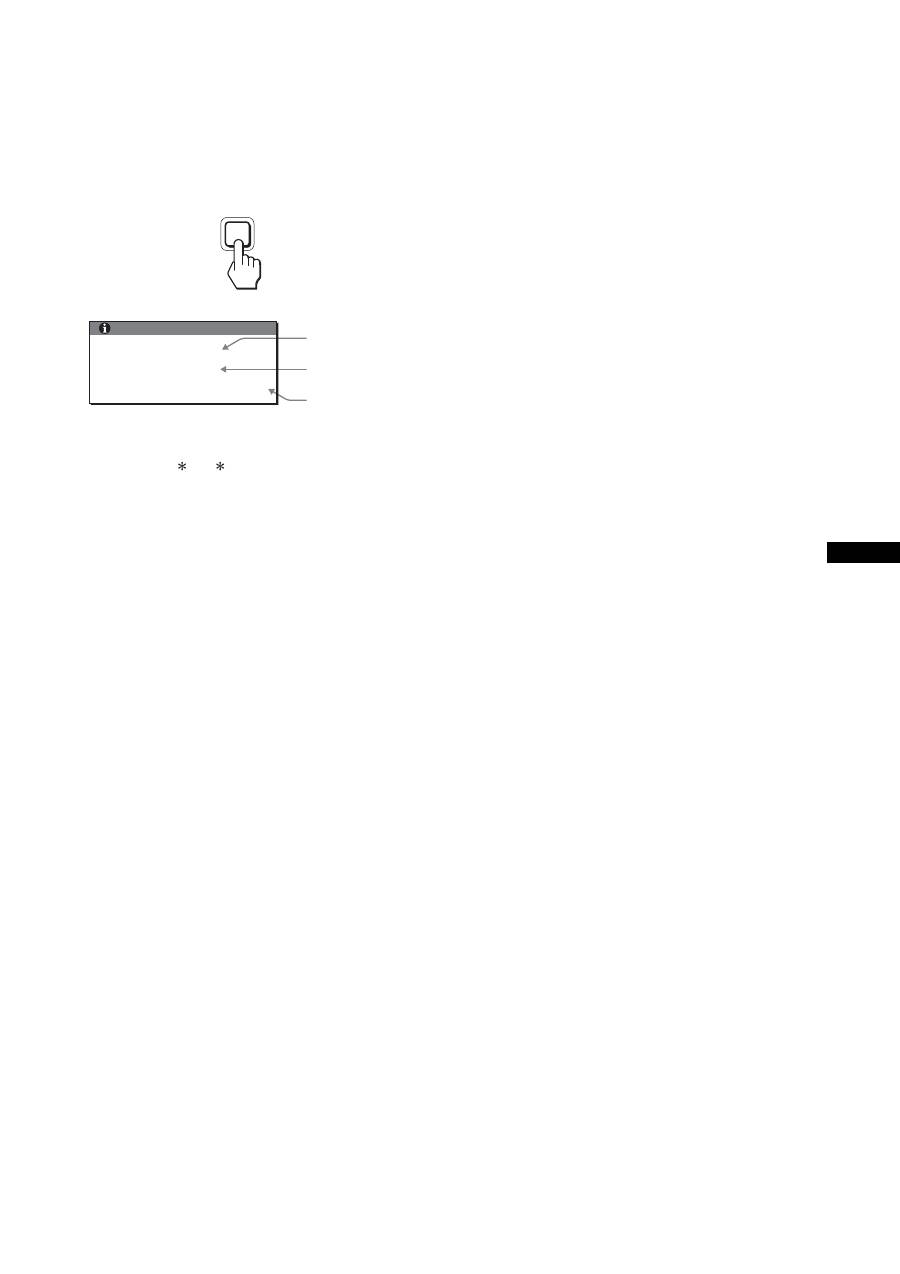
While the display is receiving a video signal, press and
hold the MENU button for more than 5 seconds until the
information box appears.
Press the MENU button again to make the box disappear.
Although the safety standard registered model name of this
display is SDM-X75 /X95 , the name of SDM-X75F/X95F/
X75K/X95K is used on sale.
If any problem persists, call your authorized Sony dealer and give
the following information:
• Model name
• Serial number
• Detailed description of the problem
• Date of purchase
• Name and specifications of your computer and graphics board
• Type of input signals (analog RGB/digital RGB)
MENU
Example
Model name
Serial number
Week and year
of manufacture
INFORMATION
MODEL : SDM-X75F
SER. NO : 1234567
MANUFACTURED : 2005-52
22
p y
AEP.fm
Specifications
1)
Recommended horizontal and vertical timing condition
• Horizontal sync width duty should be more than 4.8% of total
horizontal time or 0.8 µs, whichever is larger.
• Horizontal blanking width should be more than 2.5 µsec.
• Vertical blanking width should be more than 450 µsec.
Design and specifications are subject to change without notice.
Model name
SDM-X75F
SDM-X95F
SDM-X75K
SDM-X95K
LCD panel
Panel type: a-Si TFT Active Matrix
Picture size: inch
17.0
19.0
17.0
19.0
Input signal format
RGB operating frequency
1)
Horizontal: 28 – 80 kHz (analog RGB)
28 – 64 kHz (digital RGB)
Vertical: 48 – 75 Hz (analog RGB)
60 Hz (digital RGB)
Resolution
Horizontal: Max.1280 dots
Vertical: Max.1024 lines
Type of input signal
(Digital/Analog)
Digital
×
1/Analog
×
1
Input signal levels
Analog RGB video signal 0.7 Vp-p, 75
Ω
, positive
SYNC signal TTL level, 2.2 k
Ω
, positive or negative
Digital RGB (DVI) signal TMDS (single link)
Audio input
Stereo minijack, 0.5Vrms, 47 k
Ω
Speaker output
1 W
×
2
USB port
–
USB Full-Speed (Max12 Mbps)
A Port
×
2, B Port
× 2
Headphone jack
×
1
Power requirements
100 – 240 V, 50 – 60 Hz, Max. 1.0 A
Power consumption
Max. 45 W
Max. 50 W
Max. 55 W
Operating temperature
5 – 35 °C
Type of the stand
Height adjust
Dimensions (width/height/
depth)
Approx. 369
×
393.5 –
503.5
×
253 mm
(14
5
/
8
×
15
1
/
2
–
19
7
/
8
×
10 inches)
(with stand)
Approx. 369
×
337
×
66 mm
(14
5
/
8
×
13
1
/
4
×
2
5
/
8
inches)
(without stand)
Approx. 414
×
409.5 –
519.5
×
277.5 mm
(16
3
/
8
×
16
1
/
8
–
20
1
/
2
×
11 inches)
(with stand)
Approx. 414
×
370
×
69 mm
(16
3
/
8
×
14
5
/
8
×
2
3
/
4
inches)
(without stand)
Approx. 369
×
393.5 –
503.5
×
253 mm
(14
5
/
8
×
15
1
/
2
–
19
7
/
8
×
10 inches)
(with stand)
Approx. 369
×
337
×
66 mm
(14
5
/
8
×
13
1
/
4
×
2
5
/
8
inches)
(without stand)
Approx. 414
×
409.5 –
519.5
×
277.5 mm
(16
3
/
8
×
16
1
/
8
–
20
1
/
2
×
11 inches)
(with stand)
Approx. 414
×
370
×
69 mm
(16
3
/
8
×
14
5
/
8
×
2
3
/
4
inches)
(without stand)
Mass
Approx. 7.6 kg
(16 lb 12
1
/
8
oz)
(with stand)
Approx. 4.4 kg
(9 lb 11
1
/
4
oz)
(without stand)
Approx. 8.9 kg
(19 lb 9
7
/
8
oz)
(with stand)
Approx. 5.4 kg
(11 lb 14
1
/
2
oz)
(without stand)
Approx. 7.6 kg
(16 lb 12
1
/
8
oz)
(with stand)
Approx. 4.4 kg
(9 lb 11
1
/
4
oz)
(without stand)
Approx. 8.9 kg
(19 lb 9
7
/
8
oz)
(with stand)
Approx. 5.4 kg
(11 lb 14
1
/
2
oz)
(without stand)
Plug & Play
DDC2B
Accessories
See page 6.

display\2633895041\2633895041\2633895041SDMX75WW\02GB
SDMX75WW\02GB03APP-AEP.fm
i
TCO’99 Eco-document (for the black
model)
x
Congratulations!
You have just purchased a TCO’99 approved and labelled product! Your
choice has provided you with a product developed for professional use.
Your purchase has also contributed to reducing the burden on the
environment and also to the further development of environmentally
adapted electronics products.
x
Why do we have environmentally labelled com-
puters?
In many countries, environmental labelling has become an established
method for encouraging the adaptation of goods and services to the
environment. The main problem, as far as computers and other electronics
equipment are concerned, is that environmentally harmful substances are
used both in the products and during their manufacture. Since it is not so
far possible to satisfactorily recycle the majority of electronics equipment,
most of these potentially damaging substances sooner or later enter nature.
There are also other characteristics of a computer, such as energy
consumption levels, that are important from the viewpoints of both the
work (internal) and natural (external) environments. Since all methods of
electricity generation have a negative effect on the environment (e.g.
acidic and climate-influencing emissions, radioactive waste), it is vital to
save energy. Electronics equipment in offices is often left running
continuously and thereby consumes a lot of energy.
x
What does labelling involve?
This product meets the requirements for the TCO’99 scheme which
provides for international and environmental labelling of personal
computers. The labelling scheme was developed as a joint effort by the
TCO (The Swedish Confederation of Professional Employees), Svenska
Naturskyddsforeningen (The Swedish Society for Nature Conservation)
and Statens Energimyndighet (The Swedish National Energy
Administration).
Approval requirements cover a wide range of issues: environment,
ergonomics, usability, emission of electric and magnetic fields, energy
consumption and electrical and fire safety.
The environmental demands impose restrictions on the presence and use
of heavy metals, brominated and chlorinated flame retardants, CFCs
(freons) and chlorinated solvents, among other things. The product must
be prepared for recycling and the manufacturer is obliged to have an
environmental policy which must be adhered to in each country where the
company implements its operational policy.
The energy requirements include a demand that the computer and/or
display, after a certain period of inactivity, shall reduce its power
consumption to a lower level in one or more stages. The length of time to
reactivate the computer shall be reasonable for the user.
Labelled products must meet strict environmental demands, for example,
in respect of the reduction of electric and magnetic fields, physical and
visual ergonomics and good usability.
Below you will find a brief summary of the environmental requirements
met by this product. The complete environmental criteria document may
be ordered from:
TCO Development
SE-114 94 Stockholm, Sweden
Fax: +46 8 782 92 07
Email (Internet): development@tco.se
Current information regarding TCO’99 approved and labelled
products may also be obtained via the Internet, using the address:
http://www.tco-info.com/
x
Environmental requirements
Flame retardants
Flame retardants are present in printed circuit boards, cables, wires,
casings and housings. Their purpose is to prevent, or at least to delay the
spread of fire. Up to 30% of the plastic in a computer casing can consist
of flame retardant substances. Most flame retardants contain bromine or
chloride, and those flame retardants are chemically related to another
group of environmental toxins, PCBs. Both the flame retardants
containing bromine or chloride and the PCBs are suspected of giving rise
to severe health effects, including reproductive damage in fish-eating
birds and mammals, due to the bio-accumulative
*
processes. Flame
retardants have been found in human blood and researchers fear that
disturbances in foetus development may occur.
The relevant TCO’99 demand requires that plastic components weighing
more than 25 grams must not contain flame retardants with organically
bound bromine or chlorine. Flame retardants are allowed in the printed
circuit boards since no substitutes are available.
Cadmium
**
Cadmium is present in rechargeable batteries and in the colour-generating
layers of certain computer displays. Cadmium damages the nervous
system and is toxic in high doses. The relevant TCO’99 requirement states
that batteries, the colour-generating layers of display screens and the
electrical or electronics components must not contain any cadmium.
Mercury
**
Mercury is sometimes found in batteries, relays and switches. It damages
the nervous system and is toxic in high doses. The relevant TCO’99
requirement states that batteries may not contain any mercury. It also
demands that mercury is not present in any of the electrical or electronics
components associated with the labelled unit.
CFCs (freons)
The relevant TCO’99 requirement states that neither CFCs nor HCFCs
may be used during the manufacture and assembly of the product. CFCs
(freons) are sometimes used for washing printed circuit boards. CFCs
break down ozone and thereby damage the ozone layer in the stratosphere,
causing increased reception on earth of ultraviolet light with e.g. increased
risks of skin cancer (malignant melanoma) as a consequence.
Lead
**
Lead can be found in picture tubes, display screens, solders and
capacitors. Lead damages the nervous system and in higher doses, causes
lead poisoning. The relevant TCO’99 requirement permits the inclusion of
lead since no replacement has yet been developed.
*
Bio-accumulative is defined as substances which accumulate within
living organisms.
** Lead, Cadmium and Mercury are heavy metals which are Bio-
accumulative.

p y
AEP.fm
ii
TCO’03 Eco-document (for the silver
model)
x
Congratulations!
The display you have just purchased carries the TCO’03
Displays label. This means that your display is designed,
manufactured and tested according to some of the strictest
quality and environmental requirements in the world. This
makes for a high performance product, designed with the
user in focus that also minimizes the impact on our natural
environment.
x
Ergonomics
• Good visual ergonomics and image quality in order to
improve the working environment for the user and to
reduce sight and strain problems. Important parameters
are luminance, contrast, resolution, reflectance, colour
rendition and image stability.
x
Energy
• Energy-saving mode after a certain time – beneficial
both for the user and the environment
• Electrical safety
x
Emissions
• Electromagnetic fields
• Noise emissions
x
Ecology
• The product must be prepared for recycling and the
manufacturer must have a certified environmental
management system such as EMAS or ISO 14 001
• Restrictions on
- chlorinated and brominated flame retardants and
polymers
- heavy metals such as cadmium, mercury and lead.
The requirements included in this label have been
developed by TCO Development in co-operation with
scientists, experts, users as well as manufacturers all over
the world. Since the end of the 1980s TCO has been
involved in influencing the development of IT equipment
in a more user-friendly direction. Our labelling system
started with displays in 1992 and is now requested by users
and IT-manufacturers all over the world.
For more information, please visit
www.tcodevelopment.com
Recycling Information
x
Customer in Europe
The collection and recycling of this product has been planned
according to your country’s relevant legislation. To ensure that
this product will be collected and recycled in way that minimizes
the impact on the environment, please do the following:
1. If you purchased this product for private use, contact your
municipality or the waste collection system and bring the
product to this collection point / have the product be picked up
by the waste collection system. Alternatively, your retailer
might take back this if you purchase new equivalent equipment;
please check with your retailer whether he will take back this
product before bringing it. For information on your country’s
recycling arrangements, please contact the Sony representation
in your country (contact details at: www.sony-europe.com).
Further details on specific recycling systems can be found at the
following addresses:
- Belgium: www.recupel.be
- Netherlands: www.nvmp.nl (consumer electronics)
www.ictmilieu.nl (IT equipment)
- Norway: www.elretur.no
- Sweden: www.el-kretsen.se
- Switzerland: www.swico.ch
2. If you use this product professionally, check the product’s
delivery contract for take back / recycling arrangements and
follow the procedures described therein. Alternatively, follow
the procedures described under point 1.
x
Customer in USA
We Sony as a member of EIA recommends to visit URL below
http://www.eiae.org/
x
Customer in Asia
http://www.sony.co.jp/SonyInfo/Environment/recycle/3R.html
2-633-895-
04
(1)
© 2005 Sony Corporation
TFT LCD Color Computer Display
SDM-X75
SDM-X95
2
Owner’s Record
The model and serial numbers are located at the rear of the unit.
Record these numbers in the spaces provided below. Refer to them
whenever you call upon your dealer regarding this product.
Model No. Serial No.
To reduce the risk of fire or electric shock, do not
expose this apparatus to rain or moisture.
Dangerously high voltages are present inside the
unit. Do not open the cabinet. Refer servicing to
qualified personnel only.
FCC Notice
This equipment has been tested and found to comply with the limits
for a Class B digital device, pursuant to Part 15 of the FCC Rules.
These limits are designed to provide reasonable protection against
harmful interference in a residential installation. This equipment
generates, uses, and can radiate radio frequency energy and, if not
installed and used in accordance with the instructions, may cause
harmful interference to radio communications. However, there is no
guarantee that interference will not occur in a particular installation.
If this equipment does cause harmful interference to radio or
television reception, which can be determined by turning the
equipment off and on, the user is encouraged to try to correct the
interference by one or more of the following measures:
– Reorient or relocate the receiving antenna.
– Increase the separation between the equipment and receiver.
– Connect the equipment into an outlet on a circuit different from
that to which the receiver is connected.
– Consult the dealer or an experienced radio/TV technician for help.
You are cautioned that any changes or modifications not expressly
approved in this manual could void your authority to operate this
equipment.
N’oubliez pas de vérifier le carton fourni avec votre écran.
L’étiquette d’identification du modèle de votre écran figure à
l’arrière de celui-ci.
(for the black model)
(for the silver model)
WARNING
IMPORTANTE
Para prevenir cualquier mal funcionamiento y evitar daños, por
favor, lea detalladamente este manual de instrucciones antes
de conectar y operar este equipo.
If you have any questions about this product, you may call;
Sony Customer Information Services Center 1-800-222-7669
or http://www.sony.com/
Declaration of Conformity
Trade Name
: SONY
Model
: SDM-X75 /X95
Note
: means any number or alphanumeric
character.
Responsible Party
: Sony Electronics Inc.
Address
: 16450 W. Bernardo Dr, San Diego, CA
92127 U.S.A.
Telephone Number : 858-942-2230
This device complies with part 15 of the FCC rules. Operation is
subject to the following two conditions: (1) This device may not
cause harmful interference, and (2) this device must accept any
interference received, including interference that may cause
undesired operation.
NOTICE
This notice is applicable for USA/Canada only.
If shipped to USA/Canada, install only a UL LISTED/CSA
LABELLED power supply cord meeting the following
specifications:
SPECIFICATIONS
Plug Type
Nema-Plug 5-15p
Cord
Type SVT or SJT, minimum 3
×
18 AWG
Length
Maximum 15 feet
Rating
Minimum 7 A, 125 V
NOTICE
Cette notice s’applique aux Etats-Unis et au Canada
uniquement.
Si cet appareil est export* aux Etats-Unis ou au Canada, utiliser
le cordon d’alimentation portant la mention UL LISTED/CSA
LABELLED et remplissant les conditions suivantes:
SPECIFICATIONS
Type de fiche
Fiche Nema 5-15 broches
Cordon
Type SVT ou SJT, minimum 3
×
18 AWG
Longueur
Maximum 15 pieds
Tension
Minimum 7 A, 125 V
As an
E
NERGY
S
TAR Partner, Sony
Corporation has determined that this
product meets the
E
NERGY
S
TAR
guidelines for energy efficiency.
This monitor complies with the
TCO’99 guidelines.
This monitor complies with the
TCO’03 guidelines.
Table des matières
• Macintosh est une marque commerciale
sous licence d’Apple Computer, Inc.,
déposée aux Etats-Unis et dans d’autres
pays.
• Windows
®
est une marque commerciale
déposée de Microsoft Corporation aux
Etats-Unis et dans d’autres pays.
• IBM PC/AT et VGA sont des marques
commerciales déposées d’IBM
Corporation aux Etats-Unis.
• VESA et DDC
™
sont des marques
commerciales de Video Electronics
Standards Association.
•
E
NERGY
S
TAR est une marque
déposée aux Etats-Unis.
• Adobe et Acrobat sont des marques
commerciales de Adobe Systems
Incorporated.
• Tous les autres noms de produit
mentionnés dans le présent mode
d’emploi peuvent être des marques
commerciales ou des marques
commerciales déposées de leurs
entreprises respectives.
• De plus, les symboles
«
™
»
et
«
®
»
ne
sont pas systématiquement mentionnés
dans ce mode d’emploi.
FR
http://www.sony.net/
3
Précautions . . . . . . . . . . . . . . . . . . . . . . . . . . . . . . . . . . . . . . . . . . . . 4
Vérification du nom du modèle de l’écran. . . . . . . . . . . . . . . . . . . . . 5
Identification des composants et des commandes . . . . . . . . . . . . . . 5
Installation . . . . . . . . . . . . . . . . . . . . . . . . . . . . . . . . . . . . .6
Étape 1 :
Assemblez le support . . . . . . . . . . . . . . . . . . . . . . . . . . . . 6
Étape 2 :
Raccordez les câbles de signal vidéo . . . . . . . . . . . . . . . 7
Étape 3 :
Raccordez la souris USB ou le clavier USB ou d’autres
périphériques (modèles équipés de ports USB
uniquement) . . . . . . . . . . . . . . . . . . . . . . . . . . . . . . . . . . . 8
Étape 4 :
Raccordez les cordons audio . . . . . . . . . . . . . . . . . . . . . . 9
Étape 5 :
Branchez le cordon d’alimentation . . . . . . . . . . . . . . . . . . 9
Étape 6 :
Fixez les cordons et refermez le couvercle
des connecteurs . . . . . . . . . . . . . . . . . . . . . . . . . . . . . . . . 9
Étape 7 :
Mettez l’écran et l’ordinateur sous tension . . . . . . . . . . . 10
Étape 8 :
Réglez l’inclinaison et la hauteur . . . . . . . . . . . . . . . . . . 11
Sélection du signal d’entrée (INPUT1/INPUT2) . . . . . . . . . . . . . . . 11
Personnalisation de votre écran . . . . . . . . . . . . . . . . . .12
Pilotage par menu. . . . . . . . . . . . . . . . . . . . . . . . . . . . . . . . . . . . . . 12
Liste des options de menu . . . . . . . . . . . . . . . . . . . . . . . . . . . . . . . 13
Menu RÉGLAGE IMAGE . . . . . . . . . . . . . . . . . . . . . . . . . . . . . 14
Menu ÉCRAN (signal RVB analogique uniquement) . . . . . . . . 14
Menu POSITION MENU . . . . . . . . . . . . . . . . . . . . . . . . . . . . . . 15
Menu DÉTECTE ENTRÉE . . . . . . . . . . . . . . . . . . . . . . . . . . . . 15
Menu LANGUAGE . . . . . . . . . . . . . . . . . . . . . . . . . . . . . . . . . . 15
0
Menu RÉINITIALISATIO
(réinitialisation aux valeurs par défaut) . . . . . . . . . . . . . . . . . . . . . . 15
Menu VERROU DU MENU . . . . . . . . . . . . . . . . . . . . . . . . . . . 15
Spécifications techniques. . . . . . . . . . . . . . . . . . . . . . . .16
Contrôle du volume. . . . . . . . . . . . . . . . . . . . . . . . . . . . . . . . . . . . . 16
Fonction d’économie d’énergie . . . . . . . . . . . . . . . . . . . . . . . . . . . . 16
Réduction de la consommation électrique (Mode-ECO) . . . . . . . . 16
Fonction de réglage automatique de la luminosité
(capteur de lumière) . . . . . . . . . . . . . . . . . . . . . . . . . . . . . . . . . . . . 16
Fonction de réglage automatique de la qualité de l’image
(signal RVB analogique uniquement) . . . . . . . . . . . . . . . . . . . . . . . 17
Fonction KVM (Fonction Clavier-Vidéo-Souris) . . . . . . . . . . . . . . . 17
Dépannage . . . . . . . . . . . . . . . . . . . . . . . . . . . . . . . . . . . .18
Messages affichés . . . . . . . . . . . . . . . . . . . . . . . . . . . . . . . . . . . . . 18
Symptômes de défaillances et remèdes . . . . . . . . . . . . . . . . . . . . . 19
Spécifications. . . . . . . . . . . . . . . . . . . . . . . . . . . . . . . . . .22
TCO’99 Eco-document (for the black model) . . . . . . . . . . . . . . . . . . .i
TCO’03 Eco-document (for the silver model) . . . . . . . . . . . . . . . . . . ii
4
Précautions
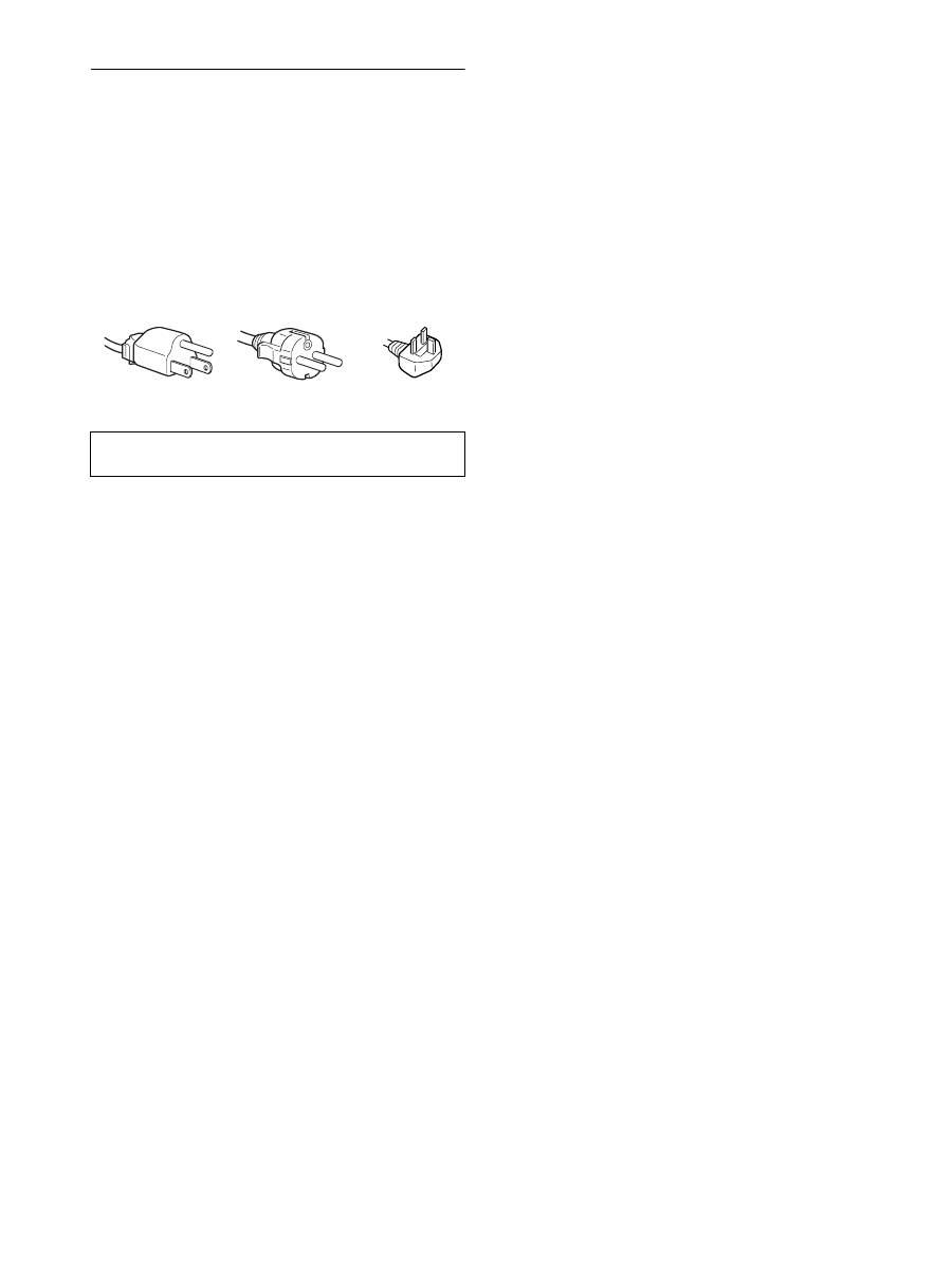
Avertissement sur les connexions d’alimentation
• Utilisez le cordon d’alimentation fourni. Si vous utilisez un
câble d’alimentation différent, assurez-vous qu’il est
compatible avec la tension secteur locale.
Pour les clients résidant aux Etats-Unis
Si vous n’employez pas le câble approprié, ce moniteur ne sera
pas conforme aux normes FCC obligatoires.
Pour les clients résidant au Royaume-Uni
Si vous utilisez le moniteur au Royaume-Uni, veuillez utiliser
le cordon d’alimentation adapté au Royaume-Uni.
Installation
N’installez pas et ne laissez pas le moniteur :
• A des endroits exposés à des températures extrêmes, par
exemple à proximité d’un radiateur, d’un conduit de chauffage
ou le rayonnement direct du soleil. L’exposition du moniteur à
des températures extrêmes, comme dans l’habitacle d’une
voiture garée en plein soleil ou à proximité d’un conduit de
chauffage, risque d’entraîner des déformations du châssis ou
des dysfonctionnements.
• A des endroits soumis à des vibrations mécaniques ou à des
chocs.
• A proximité d’appareils générant de puissants champs
magnétiques, comme un téléviseur ou d’autres appareils
électroménagers.
• A des endroits soumis à des quantités inhabituelles de poussière,
de saletés ou de sable, par exemple à côté d’une fenêtre ouverte
ou d’une porte donnant sur l’extérieur. En cas d’installation
temporaire à l’extérieur, veillez à prendre les précautions
requises contre la poussière et les saletés en suspension dans l’air.
Faute de quoi des dommages irréparables risquent de se produire.
Les orifices de ventilation, situés sur le dessus à l’arrière de
l’écran, chauffent. Veillez donc à ne pas les toucher.
Manipulation de l’écran LCD
• Ne laissez pas l’écran LCD face au soleil, car vous risquez
sinon de l’endommager. Faites donc attention si vous installez
le moniteur à côté d’une fenêtre.
• N’appuyez pas sur et veillez à ne pas érafler la surface de
l’écran LCD. Ne posez pas d’objets lourds sur l’écran LCD.
Vous risquez sinon d’altérer l’uniformité de l’écran ou de
provoquer un dysfonctionnement de l’écran LCD.
• Lorsque le moniteur est employé dans un environnement froid,
il est possible qu’une image rémanente apparaisse sur l’écran.
Il ne s’agit pas d’un dysfonctionnement. L’écran recouvre sa
condition normale dès que la température est revenue à un
niveau normal.
• Si une image fixe reste affichée pendant une longue durée, il se
peut qu’une image rémanente apparaisse pendant un certain
temps. Cette image rémanente finira par disparaître.
• Le panneau LCD chauffe en cours d’utilisation. Il ne s’agit pas
d’un dysfonctionnement.
Remarque sur l’affichage à cristaux liquides
(LCD - Liquid Crystal Display)
Veuillez noter que l’écran LCD est issu d’une
technologie de haute précision. Toutefois, il est
possible que des points noirs ou des points brillants de
lumière (rouge, bleu ou vert) apparaissent
constamment sur l’écran LCD, ainsi que des bandes de
couleurs irrégulières ou une certaine luminosité. Il ne
s’agit pas d’un dysfonctionnement.
(Pixels actifs : supérieurs à 99,99%)
Entretien
• Débranchez le cordon d’alimentation de la prise secteur avant
de procéder au nettoyage de votre moniteur.
• Nettoyez l’écran LCD avec un chiffon doux. Si vous utilisez un
liquide de nettoyage pour le verre, n’utilisez pas de nettoyant
contenant une solution antistatique ou tout autre additif
similaire, car vous risquez sinon de griffer le revêtement de
l’écran LCD.
• Nettoyez le châssis, le panneau et les commandes à l’aide d’un
chiffon doux légèrement imprégné d’une solution détergente
neutre. N’utilisez aucun type de tampon abrasif, de poudre à
récurer ou de solvant tel que de l’alcool ou de l’essence.
• Ne frottez pas, ne touchez pas et ne tapotez pas la surface de
l’écran avec des objets pointus ou abrasifs comme un stylo à
bille ou un tournevis. Ce type de contact risque de rayer le tube
image.
• Sachez qu’une détérioration des matériaux ou du revêtement de
l’écran LCD risque de se produire si le moniteur est exposé à
des solvants volatils comme des insecticides ou en cas de
contact prolongé avec des objets en caoutchouc ou en vinyle.
Transport
• Débranchez tous les câbles de l’écran. Si vous utilisez un
support à hauteur réglable, réglez-le sur la position la plus
élevée et tenez convenablement l’écran LCD par les deux côtés.
Veillez à ne pas griffer l’écran pendant le transport. Si vous
laissez tomber l’écran, vous risquez de vous blesser ou de
l’endommager.
• Pour transporter ce moniteur en vue de réparations ou de son
expédition, utilisez le carton et les matériaux de
conditionnement originaux.
• Replacez la goupille d’arrêt du support à hauteur réglable pour
immobiliser le support pendant le transport.
Elimination du moniteur
• N’éliminez pas ce moniteur avec les ordures
ménagères.
• Le tube fluorescent utilisé dans ce moniteur contient
du mercure. L’élimination de ce moniteur doit être
effectuée conformément aux réglementations des
administrations compétentes en matière de propreté
publique.
L’appareil doit être installé à proximité d’une prise de courant
aisément accessible.
Exemples de types de fiches
pour 100 à 120 V CA pour 200 à 240 V CA
pour 240 V CA
uniquement
5
FR
FR
Vérification du nom du modèle de
l’écran
Commencez par vérifier le nom du modèle de l’écran.
Le nom du modèle se trouve à l’arrière de l’écran
(Exemple : SDM-X75F).
Vous ne pouvez pas utiliser certaines fonctions et certains menus
avec certains modèles de l’écran.
Identification des composants et
des commandes
Pour plus de détails, reportez-vous aux pages indiquées entre
parenthèses.
L’illustration représente uniquement l’un des modèles
disponibles pour cet écran.
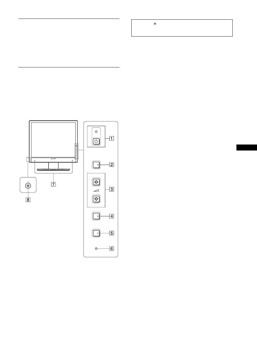
1
Commutateur
1
(alimentation) et
indicateur
1
(alimentation) (pages 10, 16)
Ce commutateur met l’écran sous tension lorsque l’indicateur
1
(alimentation) est rouge. Appuyez de nouveau sur ce
commutateur pour mettre l’écran hors tension.
Si l’indicateur
1
(alimentation) ne s’allume pas, appuyez sur
l’interrupteur MAIN POWER (
9
).
2
Touche MENU (page 12)
Cette touche permet d’activer et de désactiver l’écran de
menu.
3
Touches
m
/
M
et
2
(commande du volume) (page 12)
Ces touches permettent de sélectionner les options de menu et
d’effectuer des réglages.
4
Touche OK (page 12)
Cette touche active les réglages et les options de menu
sélectionnés à l’aide des touches
m
/
M
(
3
).
INPUT
(page 11)
Ces touches permettent de commuter le signal d’entrée vidéo
entre INPUT1 et INPUT2 lorsque deux ordinateurs sont
raccordés à l’écran. (Disponible uniquement lorsque le menu
est désactivé.)
5
Touche ECO (page 16)
Cette touche permet de réduire la consommation d’énergie.
Lorsque l’écran de menu n’est pas affiché, vous pouvez aussi
régler automatiquement la qualité de l’image du signal
d’entrée en cours en maintenant cette touche enfoncée
pendant plus de 3 secondes (Réglage automatique par touche
unique). (signal RVB analogique uniquement)
6
Capteur de lumière (page 16)
Ce capteur mesure la luminosité autour de l’écran. Veillez à
ne pas recouvrir le capteur avec du papier, etc.
7
Haut-parleurs stéréo (pages 9, 16)
Ces haut-parleurs diffusent les signaux audio sous forme de
sons.
8
Prise casque (pages 9, 16)
Cette prise transmet les signaux audio vers votre casque.
MENU
INPUT
ECO
OK
Avant de l’affichage
La marque indique des informations de spécifications
diverses selon les modèles. Pour plus de détails, reportez-
vous à la section « Spécifications » (page 22).
6
9
Interrupteur MAIN POWER (page 10)
Cet interrupteur active et désactive le commutateur MAIN
POWER de l’écran.
0
Connecteur AC IN (page 9)
Ce connecteur raccorde le cordon d’alimentation (fourni).
qa
Connecteur d’entrée DVI-D (RVB numérique)
(page 8)
Ce connecteur transmet des signaux vidéo RVB numériques
conformes à la DVI Rév. 1.0.
qs
Connecteur d’entrée HD15 (RVB analogique)
(page 8)
Ce connecteur transmet des signaux vidéo RVB analogiques
(0,700 Vc-c, positifs) et des signaux de synchronisation.
qd
Support de câble (page 9)
Cette pièce permet de maintenir les câbles et les cordons
contre l’écran.
qf
Port de téléchargement (réception) USB (page 8)
(modèles équipés de ports USB uniquement)
En raccordant la souris USB et le clavier USB à l’écran, vous
pouvez raccorder jusqu’à deux ordinateurs à l’écran en
permutant l’entrée.
qg
Port de téléchargement (envoi) USB (modèles
équipés d’un port USB uniquement)
Raccordez le câble USB à votre ordinateur et à l’écran.
qh
Orifice de verrouillage de sécurité
Le Kensington Micro Saver Security System doit être utilisé
pour l’orifice de verrouillage de sécurité.
Micro Saver Security System est une marque commerciale de
Kensington.
qj
Prise audio pour INPUT1
Cette prise capte des signaux audio lorsqu’elle est raccordée
à la prise de sortie audio d’un ordinateur ou d’un autre
appareil audio raccordé à INPUT1.
q,
Prise audio pour INPUT2
Cette prise capte des signaux audio lorsqu’elle est raccordée
à la prise de sortie audio d’un ordinateur ou d’un autre
appareil audio raccordé à INPUT2.
Installation
Avant d’utiliser votre écran, vérifiez si les accessoires suivants se
trouvent bien dans le carton d’emballage :
• Écran LCD
• Cordon d’alimentation
• Base du support
• Câble de signal vidéo HD15-HD15 (RVB analogique)
• Câble de signal vidéo DVI-D (RVB numérique)
• Câble audio (minifiche stéréo)
• Câble USB
• CD-ROM (logiciel utilitaire pour Windows et Macintosh,
mode d’emploi, etc.)
• Carte de garantie
• Guide de configuration rapide
La marque indique des informations de spécifications diverses
selon les modèles. Pour plus de détails, reportez-vous à la section
« Spécifications » (page 22).
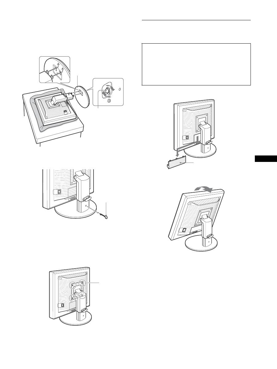
Étape 1 : Assemblez le support
x
En cas d’utilisation du support fourni-
Support fixe
1
Ouvrez le carton et retirez la base du support.
2
Vérifiez les pièces fournies.
• Avec une vis fixée sur le dessous de la base du support.
3
Posez un tapis souple ou équivalent sur un bureau,
par exemple.
Vous risquez d’endommager l’écran LCD et l’écran
proprement dit si vous le déposez directement sur le bureau.
4
Retirez l’écran du carton et posez le cadre de l’écran
le long du bord du bureau.
Arrière de l’écran
N’appuyez pas sur l’écran LCD lorsque vous placez
ou soulevez l’écran proprement dit sur un bureau ou
une surface similaire.
Cela peut endommager l’écran LCD ou affecter son
uniformité.
Écran
Support
Tapis souple ou équivalent
7
FR
FR
5
Encliquetez les parties en saillie du support sur les
orifices de la base du support afin de fixer cette
dernière.
1
Soulevez la poignée de la vis pour visser
correctement la base du support.
2
Assurez-vous que la vis est serrée et retournez la
poignée de la vis.
6
Retirez la goupille d’arrêt après avoir levé
verticalement le support à hauteur réglable.
Remarque
Ne retirez pas la goupille d’arrêt aussi longtemps que le support
demeure couché. Il risquerait de tomber ou de vous blesser si son
attache venait à se détacher de la base de manière impromptue.
x
En cas d’utilisation du support VESA
Vous pouvez fixer un support VESA d’une autre marque en
retirant le support fourni qui est déjà fixé à l’écran.
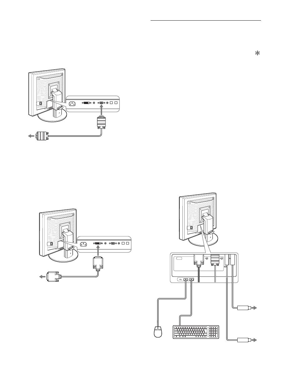
Étape 2 : Raccordez les câbles de
signal vidéo
1
Abaissez le couvercle des connecteurs en le faisant
glisser.
2
Inclinez l’écran vers le haut.
Ensuite, relevez l’angle de l’écran.
1
Base du support
2
Vis
Goupille d’arrêt
Vis compatibles
avec la norme
VESA (4)
• Mettez l’écran et l’ordinateur hors tension avant de
procéder au raccordement.
Remarques
• Ne touchez pas les broches du connecteur du câble de signal vidéo,
car vous risquez de les plier.
• Vérifiez l’alignement du connecteur pour ne pas tordre les broches
du connecteur du câble de signal vidéo.
Couvercle des connecteurs
8
3
Raccordez les câbles de signal vidéo à l’écran.
x
Raccordez un ordinateur équipé d’un
connecteur de sortie HD15 (RVB
analogique)
À l’aide du câble de signal vidéo HD15-HD15 fourni (RVB
analogique), raccordez l’ordinateur au connecteur d’entrée
HD 15 de l’écran (RVB analogique).
x
Raccordez un ordinateur équipé d’un
connecteur de sortie DVI (RVB numérique)
Raccordez l’ordinateur au connecteur d’entrée DVI-D de
l’écran (RVB numérique) à l’aide du câble de signal vidéo
DVI-D (RVB numérique) fourni.
Étape 3 : Raccordez la souris USB
ou le clavier USB ou
d’autres périphériques
(modèles équipés de
ports USB uniquement)
En raccordant la souris USB ou le clavier USB ou d’autres
périphériques, vous pouvez permuter les entrées (fonction KVM).
Pour plus d’informations, reportez-vous à la section « Fonction
KVM » (page 17).
Si vous n’utilisez pas de souris USB ou de clavier USB ou
d’autres périphériques avec votre écran, passez à l’Étape 4.
1
Raccordez le câble fourni entre l’écran et
l’ordinateur.
2
Raccordez la souris USB ou le clavier USB ou
d’autres périphériques à l’écran.
Pour l’utilisateur Macintosh :
Si vous raccordez le port USB Downstream au clavier d’un
Macintosh équipé d’un bouton de marche, celui-ci risque de
ne plus commander la mise sous tension. Actionnez le bouton
de marche de votre ordinateur ou raccordez directement le
clavier à l’ordinateur, puis mettez-le sous tension et raccordez
ensuite le port USB Downstream au clavier.
Remarques
• Le port USB de cet écran est compatible avec Windows 2000 / Windows
XP Professionnel / Windows XP Édition familiale / Macintosh.
• Si la souris USB ou le clavier USB ou d’autres périphériques sont déjà
raccordés à votre ordinateur, débranchez une fois la souris USB ou le
clavier USB ou les autres périphériques.
• Cette procédure est réservée aux ordinateurs et aux systèmes
d’exploitation compatibles USB. Pour plus d’informations, reportez-
vous au mode d’emploi de votre ordinateur ou de votre système
d’exploitation.
câble de signal vidéo HD15-HD15
(RVB analogique) (fourni)
vers le connecteur de sortie HD15 de
l’ordinateur (RVB analogique)
vers le connecteur
d’entrée HD 15
(RVB analogique)
vers le connecteur de sortie DVI
de l’ordinateur (RVB numérique)
vers le connecteur
d’entrée DVI-D
(RVB numérique)
câble de signal vidéo
DVI-D (RVB
numérique) (fourni)
AC IN
DVI-D
HD15
1
2
2
1
Vers port USB
de l’ordinateur
Vers port USB
de l’ordinateur
Câble USB
(fourni)
Câble USB (fourni)
Souris USB
Clavier USB
2
2
1
1
9
FR
FR
Étape 4 : Raccordez les cordons
audio
Raccordez la prise d’entrée audio de l’écran et la prise
de sortie audio de l’ordinateur ou d’un autre appareil
audio à l’aide du cordon audio fourni.
x
Lorsque le casque reproduit du son
Raccordez solidement le câble audio (non fourni) à la
prise casque de l’écran.
La sortie audio sera modifiée dès que le raccordement de la sortie
audio et de l’entrée audio de l’écran sera terminé.
Avec les haut-parleurs de l’écran ou le casque, vous pouvez aussi
écouter le son provenant de l’ordinateur ou de tout autre appareil
audio raccordé aux prises d’entrée audio de l’écran. Pour plus
d’informations, reportez-vous à la section « Contrôle du volume »
(page 16).
Étape 5 : Branchez le cordon
d’alimentation
1
Raccordez solidement le cordon d’alimentation
fourni au connecteur AC IN de l’écran.
2
Raccordez solidement l’autre extrémité du cordon à
une prise secteur.
Étape 6 : Fixez les cordons et
refermez le couvercle des
connecteurs
1
Faites passer les cordons et les câbles à travers le
support de câble, de la manière illustrée.
2
Refermez le couvercle des connecteurs.
Remarque
Lorsque vous rassemblez les cordons et les câbles, veillez à laisser un peu
de jeu. S’ils sont trop tendus, ils risquent de se détacher des connecteurs
ou des prises quand vous réglez l’angle de l’écran. Si vous tirez trop fort
sur les cordons et les câbles, vous risquez de les endommager.
vers l’entrée audio
cordon audio (fourni)
vers la sortie audio de
l’ordinateur ou d’un autre
appareil audio
vers la prise casque
cordon audio
(fourni)
Cordon d’alimentation (fourni)
vers AC IN
vers une prise secteur
2
1
10
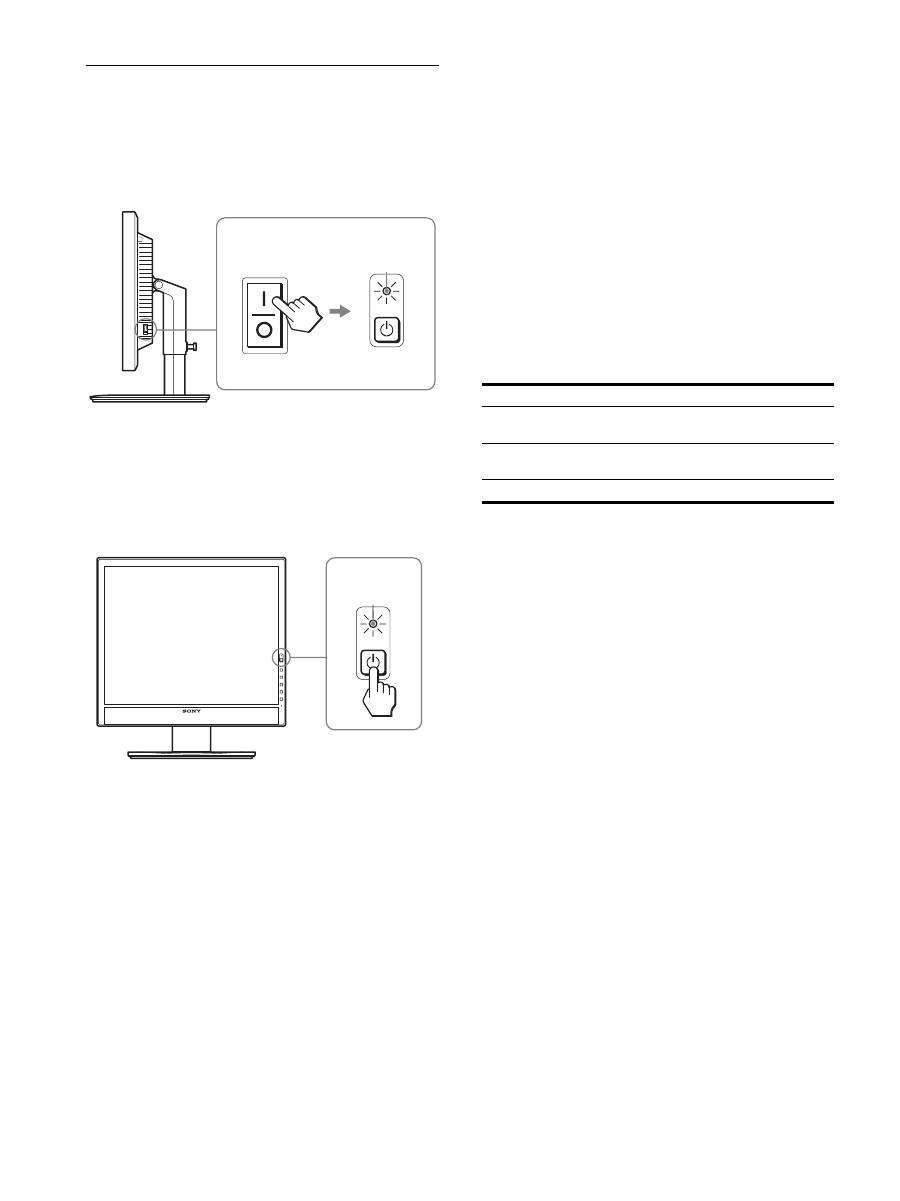
Étape 7 : Mettez l’écran et
l’ordinateur sous tension
1
Assurez-vous que l’indicateur
1
(alimentation)
clignote en rouge. Au moment de l’achat, le côté
\
de
l’interrupteur MAIN POWER est enfoncé.
Remarque
Si le côté
\
de l’interrupteur MAIN POWER situé sur le côté droit de
l’écran n’est pas enfoncé, appuyez dessus et assurez-vous que le témoin
1
(alimentation) clignote en rouge.
2
Appuyez sur le commutateur
1
(alimentation) situé
à droite, à l’avant de l’écran.
L’indicateur
1
(alimentation) s’allume en vert.
3
Mettez l’ordinateur sous tension.
Si aucune image n’apparaît sur l’écran
• Vérifiez que le cordon d’alimentation et le câble du signal
vidéo sont correctement raccordés.
• Si l’indication « D’ENTRÉE VIDÉO » apparaît sur l’écran :
– L’ordinateur est en mode d’économie d’énergie. Essayez
d’appuyer sur n’importe quelle touche du clavier ou déplacez la
souris.
– Vérifiez que le réglage du signal d’entrée est correct en
appuyant sur la touche OK (page 11).
• Si l’indication « CABLE NON CONNECTÉ » apparaît sur
l’écran :
– Vérifiez que les câbles vidéo sont bien raccordés.
– Vérifiez que le réglage du signal d’entrée est correct en
appuyant sur la touche OK (page 11).
• Si l’indication
«
HORS PLAGE FRÉQUENCES
»
apparaît
sur l’écran :
Reconnectez l’ancien écran. Réglez ensuite la carte graphique
de l’ordinateur dans les plages suivantes.
Pour des informations plus détaillées sur les messages à l’écran,
voir « Symptômes de défaillances et remèdes » à la page 19.
Vous n’avez besoin d’aucun pilote pour cet écran
L’écran prend en charge la fonction Plug & Play « DDC » et détecte
automatiquement toutes les autres informations relatives à l’écran. Il n’est
pas nécessaire d’installer de pilote pour cet ordinateur.
La première fois que vous mettez l’ordinateur sous tension après avoir
raccordé l’écran, l’assistant d’installation peut s’afficher sur l’écran. Dans
ce cas, suivez les indications affichées à l’écran. L’écran Plug & Play est
automatiquement sélectionné afin que vous puissiez l’utiliser.
La fréquence verticale devient 60 Hz.
Etant donné que les scintillements sur l’écran ne sont pas gênants, vous
pouvez l’utiliser tel quel. Vous n’avez pas besoin de régler la fréquence
verticale sur une valeur particulièrement élevée.
MAIN POWER
L’indicateur
s’allume
en rouge
L’indicateur
s’allume en vert
RVB analogique
RVB numérique
Fréquence
horizontale
28 – 80 kHz
28 – 64 kHz
Fréquence
verticale
48 – 75 Hz
60 Hz
Résolution
1 280
×
1 024 ou moins
11
FR
FR
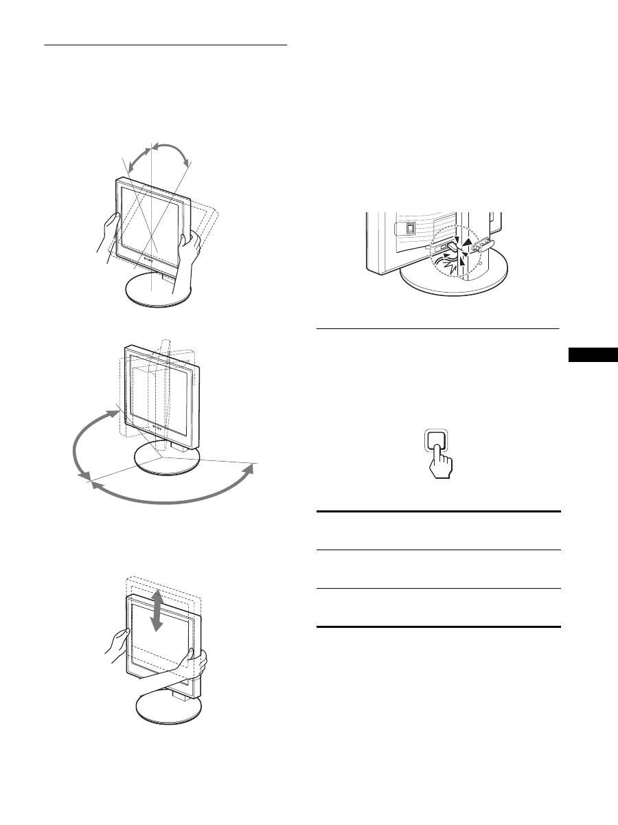
Étape 8 : Réglez l’inclinaison et la
hauteur
Cet écran peut être ajusté selon les angles illustrés ci-dessous.
Maintenez le panneau LCD par les deux côtés puis
réglez les angles d’inclinaison de l’écran.
Lorsque vous utilisez le support à hauteur réglable, la hauteur peut
aussi être réglée de la manière décrite ci-dessous.
Saisissez l’écran LCD des deux côtés, puis réglez sa
hauteur.
Pour une utilisation confortable de l’écran
Ajustez l’angle de vision de votre écran selon la hauteur de votre
bureau et de votre siège de sorte que l’écran ne réfléchisse pas la
lumière dans les yeux.
Remarques
• Lorsque vous réglez la position de l’écran, veillez à ne heurter aucun
écran, câble ou périphérique USB environnant. Veillez à déplacer
délicatement l’écran.
• Ne placez aucun objet sous l’écran lorsque vous réglez la hauteur du
support. Il risquerait d’être endommagé accidentellement.
• Lorsque vous raccordez des produits USB ou des périphériques USB à
l’écran, veillez à ce qu’ils ne heurtent pas la base du support. En
fonction de leur taille, les produits et périphériques risquent
d’endommager l’écran lorsque vous réglez son inclinaison et sa
hauteur. (modèles équipés de ports USB uniquement)
Sélection du signal d’entrée
(INPUT1/INPUT2)
Appuyez sur la touche OK.
Le signal d’entrée change chaque fois que vous appuyez sur la
touche OK.
environ 20°
environ 5°
environ
175°
environ
175°
environ 110 mm (4
11
/
32
pouces)
Message à l
’
écran (s
’
affiche
pendant environ 5 secondes
dans le coin supérieur gauche).
Configuration du signal en
entrée
ENTRÉE1 : DVI-D
Connecteur d
’
entrée DVI-D
(RVB numérique) pour
INPUT1
ENTRÉE2 : HD15
Connecteur d
’
entrée HD15
(RVB analogique) pour
INPUT2
INPUT
OK
12
Personnalisation de votre
écran
Vous pouvez effectuer de nombreux réglages de votre écran à
l’aide des menus affichés.
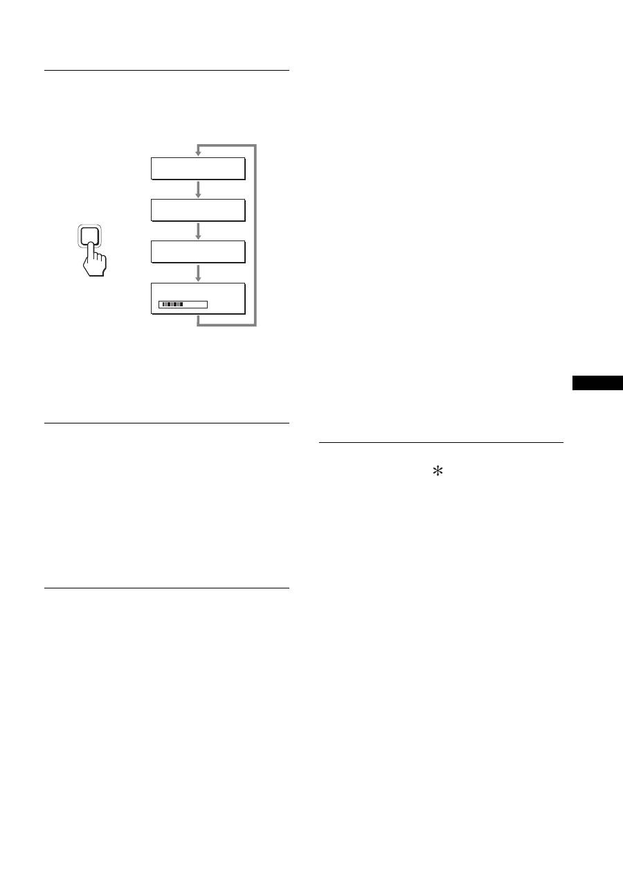
Pilotage par menu
1
Affichez le menu principal.
Appuyez sur la touche MENU pour afficher le menu principal
sur votre écran.
2
Sélectionnez le menu que vous souhaitez régler.
Appuyez sur les touches
m
/
M
pour afficher le menu de votre
choix. Appuyez sur la touche OK pour sélectionner un
paramètre.
3
Réglez l’option.
Appuyez sur les touches
m
/
M
pour effectuer votre réglage,
puis appuyez sur la touche OK.
Lorsque vous appuyez sur OK, le réglage est mémorisé et
l’appareil revient au menu précédent.
4
Refermez le menu.
Appuyez une fois sur la touche MENU pour revenir en mode
de visualisation normale. Si vous n’actionnez aucune touche,
le menu se referme automatiquement au bout d’environ
45 secondes.
x
Réinitialisation des réglages à leurs valeurs
par défaut
Vous pouvez réinitialiser les réglages à l’aide du menu
RÉINITIALISATIO.
Pour plus d’informations sur la réinitialisation des réglages, voir
0
(RÉINITIALISATIO) à la page 15.
Avant de procéder aux réglages
Raccordez l’écran et l’ordinateur, puis mettez-les sous tension.
Pour obtenir des résultats optimaux, attendez au moins
30 minutes avant d’effectuer des réglages après avoir raccordé
l’écran à l’ordinateur et l’avoir mis sous tension.
MENU
INPUT
OK
,
INPUT
OK
,
MENU
