Sony SDM-X75FB – page 2
Manual for Sony SDM-X75FB
Table of contents
p y
WW.fm
21
保証書とアフターサー ビス
保証書
・ この製品は保証書が添付されていますので、お買い上げ
の際、お買い上げ店でお受け取りください。
・ 所定事項の記入および記載内容をお確かめのうえ、大切
に保存してください。
・ 保証期間は、お買い上げ日より 3 年間です。
アフターサービスについて
調子が悪いときはまずチェックを
b
「故障かな?と思ったら」の項を参考にして、故障かどう
かをお調べください。
それでも具合が悪いときはサービス窓口へ
b
お買い上げ店、または添付の「ソニーご相談窓口のご案
内」にある、お近くのソニーサービス窓口にご相談くだ
さい。
保証期間中の修理は
b
保証書の記載内容に基づいて修理させていただきます。
くわしくは保証書をご覧ください。
保証期間経過後の修理は
b
修理によって機能が維持できる場合は、ご要望により有
料で修理させていただきます。
部品の保有期間について
当社では、コンピュータディスプレイの補修用性能部品
(製品の機能を維持するために必要な部品)を、製造打ち
切り後 8 年間保有しています。この部品保有期間を修理可
能の期間とさせていただきます。
保有期間が経過した後も、故障箇所によっては、修理可能
の場合がありますので、お買い上げ店か、サービス窓口に
ご相談ください。
ご相談になるときは次のことをお知らせください。
型名:ディスプレイが梱包されていた箱や本体後面の ID ラ
ベルをご覧になり、お使いのディスプレイの型名をご確認
ください。
製造番号:
故障の状態:できるだけ詳しく
購入年月日:
This display is designed for use in Japan only and
cannot be used in any other country.
お買い上げ店
TEL.
お近くのサービスステーション
TEL.
p y
WW.fm
22
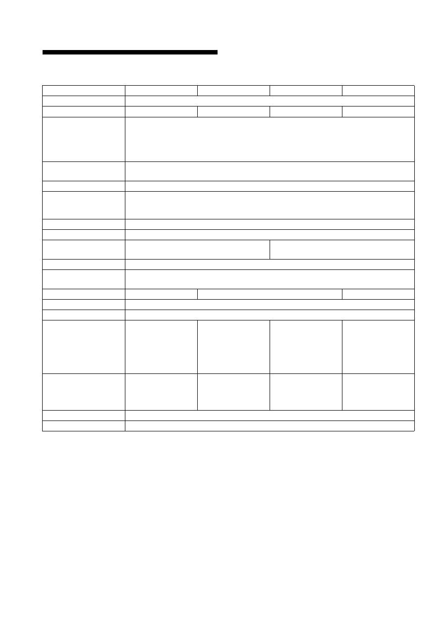
主な仕様
1)
推奨周波数タイミング
・ 水平同期幅率:水平周波数のタイミングの合計の 4.8% 以上、
または 0.8 m
µ
s のどちらか大きい方
・ 水平ブランキング幅:2.5
µ
s 以上
・ 垂直ブランキング幅:450
µ
s 以上
本機の使用および外観は、改良のため予告なく変更するこ
とがありますが、ご了承ください。
型名
SDM-X75F
SDM-X95F
SDM-X75K
SDM-X95K
LCD パネル
a-Si TFT アクティブマトリックス
画面サイズ
17 インチ(43 cm) 19 インチ(48 cm) 17 インチ(43 cm) 19 インチ(48 cm)
入力信号フォーマット
RGB 動作周波数
1)
水平:28 ~ 80 kHz(アナログ RGB)
28 ~ 64 kHz(デジタル RGB)
垂直:48 ~ 75 Hz(アナログ RGB)
60 Hz(デジタル RGB)
解像度
水平:最大 1280 ドット
垂直:最大 1024 ライン
入力信号の種類
デジタル×1 アナログ×1
入力信号レベル
アナログ RGB 信号:0.7 Vp-p、75
Ω
、正極性
同期信号:TTL レベル、2.2 k
Ω
、極性自由
デジタル RGB(DVI)信号: TMDS(Single link)
音声入力
ステレオミニジャック、0.5 Vrms、47k
Ω
スピーカー出力
1W × 2
USB 端子
–
USB Full-Speed (Max12 Mbps)
A ポート× 2、B ポート× 2、
ヘッドホン端子
×1
電源
AC100 ~ 240 V/50-60 Hz
最大 1.0 A
消費電力量
最大 45 W
最大 50 W
最大 55 W
動作温度
5 ~ 35 ℃
スタンドの種類
高さ調整スタンド
最大外形寸法
(幅 / 高さ / 奥行き)
約 369 × 393.5 -
503.5 × 253 mm
( スタンド付 )
約 369 × 337 ×
66 mm
( スタンドなし )
約 414 × 409.5 -
519.5 × 277.5 mm
( スタンド付 )
約 414 × 370 ×
69 mm
( スタンドなし )
約 369 × 393.5 -
503.5 × 253 mm
( スタンド付 )
約 369 × 337 ×
66 mm
( スタンドなし )
約 414 × 409.5 -
519.5 × 277.5 mm
( スタンド付 )
約 414 × 370 ×
69 mm
( スタンドなし )
質量
約 7.6 kg
( スタンド付 )
約 4.4 kg
( スタンドなし )
約 8.9 kg
( スタンド付 )
約 5.4 kg
( スタンドなし )
約 7.6 kg
( スタンド付 )
約 4.4 kg
( スタンドなし )
約 8.9 kg
( スタンド付 )
約 5.4 kg
( スタンドなし )
プラグ & プレイ機能
DDC2B
付属品
6 ページをご覧ください。

display\2633895041\2633895041\2633895041SDMX75WW\01JP
SDMX75WW\01JP03APP-AEP.fm
i
TCO’99 Eco-document (for the black
model)
x
Congratulations!
You have just purchased a TCO’99 approved and labelled product! Your
choice has provided you with a product developed for professional use.
Your purchase has also contributed to reducing the burden on the
environment and also to the further development of environmentally
adapted electronics products.
x
Why do we have environmentally labelled com-
puters?
In many countries, environmental labelling has become an established
method for encouraging the adaptation of goods and services to the
environment. The main problem, as far as computers and other electronics
equipment are concerned, is that environmentally harmful substances are
used both in the products and during their manufacture. Since it is not so
far possible to satisfactorily recycle the majority of electronics equipment,
most of these potentially damaging substances sooner or later enter nature.
There are also other characteristics of a computer, such as energy
consumption levels, that are important from the viewpoints of both the
work (internal) and natural (external) environments. Since all methods of
electricity generation have a negative effect on the environment (e.g.
acidic and climate-influencing emissions, radioactive waste), it is vital to
save energy. Electronics equipment in offices is often left running
continuously and thereby consumes a lot of energy.
x
What does labelling involve?
This product meets the requirements for the TCO’99 scheme which
provides for international and environmental labelling of personal
computers. The labelling scheme was developed as a joint effort by the
TCO (The Swedish Confederation of Professional Employees), Svenska
Naturskyddsforeningen (The Swedish Society for Nature Conservation)
and Statens Energimyndighet (The Swedish National Energy
Administration).
Approval requirements cover a wide range of issues: environment,
ergonomics, usability, emission of electric and magnetic fields, energy
consumption and electrical and fire safety.
The environmental demands impose restrictions on the presence and use
of heavy metals, brominated and chlorinated flame retardants, CFCs
(freons) and chlorinated solvents, among other things. The product must
be prepared for recycling and the manufacturer is obliged to have an
environmental policy which must be adhered to in each country where the
company implements its operational policy.
The energy requirements include a demand that the computer and/or
display, after a certain period of inactivity, shall reduce its power
consumption to a lower level in one or more stages. The length of time to
reactivate the computer shall be reasonable for the user.
Labelled products must meet strict environmental demands, for example,
in respect of the reduction of electric and magnetic fields, physical and
visual ergonomics and good usability.
Below you will find a brief summary of the environmental requirements
met by this product. The complete environmental criteria document may
be ordered from:
TCO Development
SE-114 94 Stockholm, Sweden
Fax: +46 8 782 92 07
Email (Internet): development@tco.se
Current information regarding TCO’99 approved and labelled
products may also be obtained via the Internet, using the address:
http://www.tco-info.com/
x
Environmental requirements
Flame retardants
Flame retardants are present in printed circuit boards, cables, wires,
casings and housings. Their purpose is to prevent, or at least to delay the
spread of fire. Up to 30% of the plastic in a computer casing can consist
of flame retardant substances. Most flame retardants contain bromine or
chloride, and those flame retardants are chemically related to another
group of environmental toxins, PCBs. Both the flame retardants
containing bromine or chloride and the PCBs are suspected of giving rise
to severe health effects, including reproductive damage in fish-eating
birds and mammals, due to the bio-accumulative* processes. Flame
retardants have been found in human blood and researchers fear that
disturbances in foetus development may occur.
The relevant TCO’99 demand requires that plastic components weighing
more than 25 grams must not contain flame retardants with organically
bound bromine or chlorine. Flame retardants are allowed in the printed
circuit boards since no substitutes are available.
Cadmium
**
Cadmium is present in rechargeable batteries and in the colour-generating
layers of certain computer displays. Cadmium damages the nervous
system and is toxic in high doses. The relevant TCO’99 requirement states
that batteries, the colour-generating layers of display screens and the
electrical or electronics components must not contain any cadmium.
Mercury
**
Mercury is sometimes found in batteries, relays and switches. It damages
the nervous system and is toxic in high doses. The relevant TCO’99
requirement states that batteries may not contain any mercury. It also
demands that mercury is not present in any of the electrical or electronics
components associated with the labelled unit.
CFCs (freons)
The relevant TCO’99 requirement states that neither CFCs nor HCFCs
may be used during the manufacture and assembly of the product. CFCs
(freons) are sometimes used for washing printed circuit boards. CFCs
break down ozone and thereby damage the ozone layer in the stratosphere,
causing increased reception on earth of ultraviolet light with e.g. increased
risks of skin cancer (malignant melanoma) as a consequence.
Lead
**
Lead can be found in picture tubes, display screens, solders and
capacitors. Lead damages the nervous system and in higher doses, causes
lead poisoning. The relevant TCO’99 requirement permits the inclusion of
lead since no replacement has yet been developed.
*
Bio-accumulative is defined as substances which accumulate within
living organisms.
** Lead, Cadmium and Mercury are heavy metals which are Bio-
accumulative.

p y
AEP.fm
ii
TCO’03 Eco-document (for the silver
model)
x
Congratulations!
The display you have just purchased carries the TCO’03
Displays label. This means that your display is designed,
manufactured and tested according to some of the strictest
quality and environmental requirements in the world. This
makes for a high performance product, designed with the
user in focus that also minimizes the impact on our natural
environment.
x
Ergonomics
• Good visual ergonomics and image quality in order to
improve the working environment for the user and to
reduce sight and strain problems. Important parameters
are luminance, contrast, resolution, reflectance, colour
rendition and image stability.
x
Energy
• Energy-saving mode after a certain time – beneficial
both for the user and the environment
• Electrical safety
x
Emissions
• Electromagnetic fields
• Noise emissions
x
Ecology
• The product must be prepared for recycling and the
manufacturer must have a certified environmental
management system such as EMAS or ISO 14 001
• Restrictions on
- chlorinated and brominated flame retardants and
polymers
- heavy metals such as cadmium, mercury and lead.
The requirements included in this label have been
developed by TCO Development in co-operation with
scientists, experts, users as well as manufacturers all over
the world. Since the end of the 1980s TCO has been
involved in influencing the development of IT equipment
in a more user-friendly direction. Our labelling system
started with displays in 1992 and is now requested by users
and IT-manufacturers all over the world.
For more information, please visit
www.tcodevelopment.com
Recycling Information
x
Customer in Europe
The collection and recycling of this product has been planned
according to your country’s relevant legislation. To ensure that
this product will be collected and recycled in way that minimizes
the impact on the environment, please do the following:
1. If you purchased this product for private use, contact your
municipality or the waste collection system and bring the
product to this collection point / have the product be picked up
by the waste collection system. Alternatively, your retailer
might take back this if you purchase new equivalent equipment;
please check with your retailer whether he will take back this
product before bringing it. For information on your country’s
recycling arrangements, please contact the Sony representation
in your country (contact details at: www.sony-europe.com).
Further details on specific recycling systems can be found at the
following addresses:
- Belgium: www.recupel.be
- Netherlands: www.nvmp.nl (consumer electronics)
www.ictmilieu.nl (IT equipment)
- Norway: www.elretur.no
- Sweden: www.el-kretsen.se
- Switzerland: www.swico.ch
2. If you use this product professionally, check the product’s
delivery contract for take back / recycling arrangements and
follow the procedures described therein. Alternatively, follow
the procedures described under point 1.
x
Customer in USA
We Sony as a member of EIA recommends to visit URL below
http://www.eiae.org/
x
Customer in Asia
http://www.sony.co.jp/SonyInfo/Environment/recycle/3R.html
2-633-895-
04
(1)
© 2005 Sony Corporation
TFT LCD Color Computer Display
p y
g
p
SDM-X75
SDM-X95
2
p y
g
g
p
Owner’s Record
The model and serial numbers are located at the rear of the unit.
Record these numbers in the spaces provided below. Refer to them
whenever you call upon your dealer regarding this product.
Model No. Serial No.
To reduce the risk of fire or electric shock, do not
expose this apparatus to rain or moisture.
Dangerously high voltages are present inside the
unit. Do not open the cabinet. Refer servicing to
qualified personnel only.
FCC Notice
This equipment has been tested and found to comply with the limits
for a Class B digital device, pursuant to Part 15 of the FCC Rules.
These limits are designed to provide reasonable protection against
harmful interference in a residential installation. This equipment
generates, uses, and can radiate radio frequency energy and, if not
installed and used in accordance with the instructions, may cause
harmful interference to radio communications. However, there is no
guarantee that interference will not occur in a particular installation.
If this equipment does cause harmful interference to radio or
television reception, which can be determined by turning the
equipment off and on, the user is encouraged to try to correct the
interference by one or more of the following measures:
– Reorient or relocate the receiving antenna.
– Increase the separation between the equipment and receiver.
– Connect the equipment into an outlet on a circuit different from
that to which the receiver is connected.
– Consult the dealer or an experienced radio/TV technician for help.
You are cautioned that any changes or modifications not expressly
approved in this manual could void your authority to operate this
equipment.
Be sure to confirm the carton that came with your display. The ID
label of your display model is located at the rear of the display.
(for the black model)
(for the silver model)
WARNING
IMPORTANTE
Para prevenir cualquier mal funcionamiento y evitar daños, por
favor, lea detalladamente este manual de instrucciones antes
de conectar y operar este equipo.
If you have any questions about this product, you may call;
Sony Customer Information Services Center 1-800-222-7669
or http://www.sony.com/
Declaration of Conformity
Trade Name
: SONY
Model
: SDM-X75 /X95
Note
: means any number or alphanumeric
character.
Responsible Party
: Sony Electronics Inc.
Address
: 16450 W. Bernardo Dr, San Diego, CA
92127 U.S.A.
Telephone Number : 858-942-2230
This device complies with part 15 of the FCC rules. Operation is
subject to the following two conditions: (1) This device may not
cause harmful interference, and (2) this device must accept any
interference received, including interference that may cause
undesired operation.
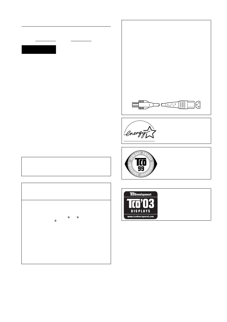
NOTICE
This notice is applicable for USA/Canada only.
If shipped to USA/Canada, install only a UL LISTED/CSA
LABELLED power supply cord meeting the following
specifications:
SPECIFICATIONS
Plug Type
Nema-Plug 5-15p
Cord
Type SVT or SJT, minimum 3
×
18 AWG
Length
Maximum 15 feet
Rating
Minimum 7 A, 125 V
NOTICE
Cette notice s’applique aux Etats-Unis et au Canada
uniquement.
Si cet appareil est export* aux Etats-Unis ou au Canada, utiliser
le cordon d’alimentation portant la mention UL LISTED/CSA
LABELLED et remplissant les conditions suivantes:
SPECIFICATIONS
Type de fiche
Fiche Nema 5-15 broches
Cordon
Type SVT ou SJT, minimum 3
×
18 AWG
Longueur
Maximum 15 pieds
Tension
Minimum 7 A, 125 V
As an
E
NERGY
S
TAR Partner, Sony
Corporation has determined that this
product meets the
E
NERGY
S
TAR
guidelines for energy efficiency.
This monitor complies with the
TCO’99 guidelines.
This monitor complies with the
TCO’03 guidelines.
Table of Contents
p y
AEPTOC.fm
• Macintosh is a trademark licensed to
Apple Computer, Inc., registered in the
U.S.A. and other countries.
• Windows
®
is registered trademarks of
Microsoft Corporation in the United
States and other countries.
• IBM PC/AT and VGA are registered
trademarks of IBM Corporation of the
U.S.A.
• VESA and DDC
™
are trademarks of the
Video Electronics Standards
Association.
•
E
NERGY
S
TAR is a U.S. registered
mark.
• Adobe and Acrobat are trademarks of
Adobe Systems Incorporated.
• All other product names mentioned
herein may be the trademarks or
registered trademarks of their respective
companies.
• Furthermore, “
™
” and “
®
” are not
mentioned in each case in this manual.
3
GB
http://www.sony.net/
Precautions . . . . . . . . . . . . . . . . . . . . . . . . . . . . . . . . . . . . . . . . . . . . 4
Checking the model name of the display . . . . . . . . . . . . . . . . . . . . . 5
Identifying parts and controls . . . . . . . . . . . . . . . . . . . . . . . . . . . . . . 5
Setup . . . . . . . . . . . . . . . . . . . . . . . . . . . . . . . . . . . . . . . . . .6
Setup 1:
Assemble the stand . . . . . . . . . . . . . . . . . . . . . . . . . . . . . . 6
Setup 2:
Connect the video signal cables . . . . . . . . . . . . . . . . . . . . 7
Setup 3:
Connect the USB mouse or the USB keyboard or other
devices (USB port-equipped models only) . . . . . . . . . . . . 8
Setup 4:
Connect the audio cords . . . . . . . . . . . . . . . . . . . . . . . . . . 9
Setup 5:
Connect the power cord . . . . . . . . . . . . . . . . . . . . . . . . . 10
Setup 6:
Secure the cords and close the connector cover . . . . . . 10
Setup 7:
Turn on the display and computer . . . . . . . . . . . . . . . . . . 10
Setup 8:
Adjust the tilt and height . . . . . . . . . . . . . . . . . . . . . . . . . 11
Selecting the input signal (INPUT1/INPUT2) . . . . . . . . . . . . . . . . . 12
Customizing Your Display . . . . . . . . . . . . . . . . . . . . . . .13
Navigating the menu . . . . . . . . . . . . . . . . . . . . . . . . . . . . . . . . . . . . 13
Menu options list. . . . . . . . . . . . . . . . . . . . . . . . . . . . . . . . . . . . . . . 14
PICTURE ADJUST menu . . . . . . . . . . . . . . . . . . . . . . . . . . . . . 14
SCREEN menu (analog RGB signal only) . . . . . . . . . . . . . . . . 15
MENU POSITION menu . . . . . . . . . . . . . . . . . . . . . . . . . . . . . . 15
INPUT SENSING menu . . . . . . . . . . . . . . . . . . . . . . . . . . . . . . . 15
LANGUAGE menu . . . . . . . . . . . . . . . . . . . . . . . . . . . . . . . . . . . 16
0
RESET menu (reset to the default setting) . . . . . . . . . . . . . . . . 16
MENU LOCK menu . . . . . . . . . . . . . . . . . . . . . . . . . . . . . . . . . 16
Technical Features . . . . . . . . . . . . . . . . . . . . . . . . . . . . .16
Controlling the volume . . . . . . . . . . . . . . . . . . . . . . . . . . . . . . . . . . 16
Power saving function. . . . . . . . . . . . . . . . . . . . . . . . . . . . . . . . . . . 16
Reducing the power consumption (ECO mode) . . . . . . . . . . . . . . . 17
Automatic brightness adjustment function (light sensor) . . . . . . . . 17
Automatic picture quality adjustment function (analog RGB signal
only) . . . . . . . . . . . . . . . . . . . . . . . . . . . . . . . . . . . . . . . . . . . . . . . . 17
KVM function (Keyboard-Video-Mouse function) . . . . . . . . . . . . . . 17
Troubleshooting. . . . . . . . . . . . . . . . . . . . . . . . . . . . . . . .18
On-screen messages . . . . . . . . . . . . . . . . . . . . . . . . . . . . . . . . . . . 18
Trouble symptoms and remedies . . . . . . . . . . . . . . . . . . . . . . . . . . 19
Specifications. . . . . . . . . . . . . . . . . . . . . . . . . . . . . . . . . .22
TCO’99 Eco-document (for the black model) . . . . . . . . . . . . . . . . . . .i
TCO’03 Eco-document (for the silver model) . . . . . . . . . . . . . . . . . . ii
4
p y
AEP.fm
Precautions
Warning on power connections
• Use the supplied power cord. If you use a different power cord,
be sure that it is compatible with your local power supply.
For the customers in the U.S.A.
If you do not use the appropriate cord, this display will not
conform to mandatory FCC standards.
For the customers in the UK
If you use the display in the UK, be sure to use the appropriate
UK power cord.
Installation
Do not install or leave the display:
• In places subject to extreme temperatures, for example near a
radiator, heating vent, or in direct sunlight. Subjecting the
display to extreme temperatures, such as in an automobile
parked in direct sunlight or near a heating vent, could cause
deformations of the casing or malfunctions.
• In places subject to mechanical vibration or shock.
• Near any equipment that generates a strong magnetic field,
such as a TV or various other household appliances.
• In places subject to inordinate amounts of dust, dirt, or sand, for
example near an open window or an outdoor exit. If setting up
temporarily in an outdoor environment, be sure to take
adequate precautions against airborne dust and dirt. Otherwise
irreparable malfunctions could occur.
Be careful not to touch the air vents on the upper rear of the
display, since they become heated.
Handling the LCD screen
• Do not leave the LCD screen facing the sun as it can damage
the LCD screen. Take care when you place the display by a
window.
• Do not push on or scratch the LCD screen. Do not place a heavy
object on the LCD screen. This may cause the screen to lose
uniformity or cause LCD panel malfunctions.
• If the display is used in a cold place, a residual image may
appear on the screen. This is not a malfunction. The screen
returns to normal as the temperature rises to a normal operating
level.
• If a still picture is displayed for a long time, a residual image
may appear for a while. The residual image will eventually
disappear.
• The LCD panel becomes warm during operation. This is not a
malfunction.
Note on the LCD (Liquid Crystal Display)
Please note that the LCD screen is made with high-
precision technology. However, black points or bright
points of light (red, blue, or green) may appear
constantly on the LCD screen, and irregular colored
stripes or brightness may appear on the LCD screen.
This is not malfunction.
(Effective dots: more than 99.99%)
Maintenance
• Be sure to unplug the power cord from the power outlet before
cleaning your display.
• Clean the LCD screen with a soft cloth. If you use a glass
cleaning liquid, do not use any type of cleaner containing an
anti-static solution or similar additive as this may scratch the
LCD screen’s coating.
• Clean the cabinet, panel, and controls with a soft cloth lightly
moistened with a mild detergent solution. Do not use any type
of abrasive pad, scouring powder, or solvent, such as alcohol or
benzine.
• Do not rub, touch, or tap the surface of the screen with sharp or
abrasive items such as a ballpoint pen or screwdriver. This type
of contact may result in a scratched picture tube.
• Note that material deterioration or LCD screen coating
degradation may occur if the display is exposed to volatile
solvents such as insecticide, or if prolonged contact is
maintained with rubber or vinyl materials.
Transportation
• Disconnect all the cables from the display. If you use a height
adjustable stand adjust its height to the highest position and
hold both sides of the LCD display securely. Be careful not to
scratch the screen when transporting. If you drop the display,
you may injured or the display may be damaged.
• When you transport this display for repair or shipment, use the
original carton and packing materials.
• Replace the stopper pin for the height adjustable stand to fix the
stand during the transportation.
Disposal of the display
• Do not dispose of this display with general
household waste.
• The fluorescent tube used in this display contains
mercury. Disposal of this display must be carried out
in accordance to the regulations of your local
sanitation authority.
For customers in the United States
This product contains mercury. Disposal of this product may be
regulated if sold in the United States. For disposal or recycling
information, please contact your local authorities or the
Electronics Industries Alliance (http://www.eiae.org).
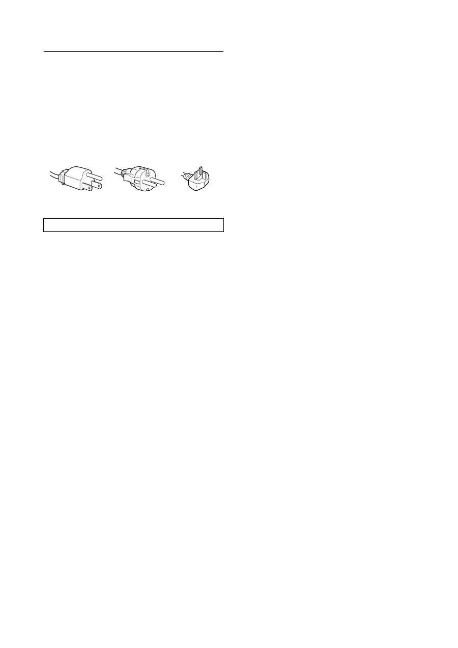
The equipment should be installed near an easily accessible outlet.
Example of plug types
for 100 to 120 V AC
for 200 to 240 V AC
for 240 V AC only
5
GB
p y
AEP.fm
Checking the model name of the
display
Check the model name of the display first.
The model name is located at the rear of the display (Example:
SDM-X75F).
You cannot use some of the functions or menu options for
certain display models.
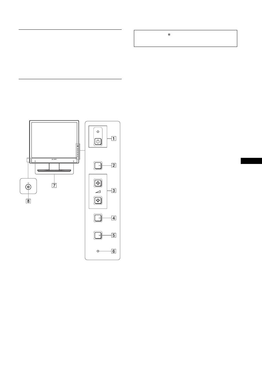
Identifying parts and controls
See the pages in parentheses for further details.
The illustration only shows one of all the models that are available
for this display.
1
1
(Power) switch and
1
(power) indicator
(pages 10, 16)
This switch turns the display on when
1
(power) indicator is
red. To turn the display off, press this switch again.
If the
1
(power) indicator fails to light, press the MAIN
POWER switch (
9
).
2
MENU button (page 12)
This button turns the menu screen on and off.
3
m
/
M
and
2
(volume control) buttons (page 12)
These buttons are used to select the menu items and make
adjustments.
4
OK button (page 12)
This button activates the selected menu item and adjustments
made using the
m
/
M
buttons (
3
).
INPUT
(page 11)
These buttons switch the video input signal between INPUT1
and INPUT2 when two computers are connected to the
display. (Only available when menu is turned off.)
5
ECO button (page 16)
This button is used to reduce the power consumption.
When the menu screen is not displayed, you can also
automatically adjust the picture quality for the current input
signal while keeping pressing this button for more than 3
seconds (One touch Auto adjust). (analog RGB signal only)
6
Light sensor (page 16)
This sensor measures the brightness of the area surrounding
the display. Be sure not to cover the sensor with paper, etc.
7
Stereo speakers (pages 9, 16)
These speakers output audio signals as sound.
8
Headphone jack (pages 9, 16)
This jack outputs audio signals to your headphones.
MENU
INPUT
ECO
OK
Front of the display
The contents with mark for specifications vary
depending on the models. For details, see “Specifications”
(page 22).
6
p y
AEP.fm
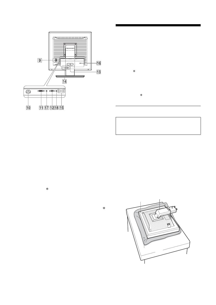
9
MAIN POWER switch (page 10)
This switch is to turn the MAIN POWER button of the display
on and off.
0
AC IN connector (page 9)
This connector connects the power cord (supplied).
qa
DVI-D input connector (digital RGB) (page 8)
This connector inputs digital RGB video signals that comply
with DVI Rev.1.0.
qs
HD15 input connector (analog RGB) (page 8)
This connector inputs analog RGB video signals (0.700 Vp-p,
positive) and sync signals.
qd
Cable holder (page 9)
This part secures cables and cords to the display.
qf
USB downstream port (page 8) (USB port-equipped
models only)
Connecting the USB mouse and USB keyboard to the display,
you can connect up to two computers to the display switching
the input back and forth.
qg
USB upstream port (USB port-equipped models only)
Connect the USB cable to your computer and display.
qh
Security lock hole
The Kensington Micro Saver Security System should be used
for the security lock hole.
Micro Saver Security System is a trademark of Kensington.
qj
Audio Jack for INPUT1
This jack inputs audio signals when connected to the audio
output jack of a computer or other audio equipment connected
to INPUT1.
q,
Audio Jack for INPUT2
This jack inputs audio signals when connected to the audio
output jack of a computer or other equipment connected to
INPUT2.
Setup
Before using your display, check that the following items are
included in your carton:
• LCD display
• Power cord
• Stand Base
• HD15-HD15 video signal cable (analog RGB)
• DVI-D video signal cable (digital RGB)
• Audio cord (stereo miniplug)
• USB cable
• CD-ROM (utility software for Windows/Macintosh, Operating
Instructions, etc.)
• Warranty card
• Quick Setup Guide
The contents with mark for specifications vary depending on
the models. For details, see “Specifications” (page 22).
Setup 1: Assemble the stand
x
When using supplied stand
1
Open the carton and take out the stand base.
2
Confirm the supplied items.
• With a screw attached to the bottom of Stand Base.
3
Put a soft mat or a like on a desk or a like.
You may damage the LCD screen and the display itself, if
putting the display directly on the desk.
4
Take the display out from the carton and then place
the frame of the laid display along the edge of the
desk.
Rear of the display
Do not press the LCD screen when placing or raising
the display straight on a desk or a like.
It may affect the uniformity of the screen or damage
the LCD display.
Display
Stand
Soft mat or a like
7
GB
p y
AEP.fm
5
Hook the Stand Base holes onto the prongs of stand
to attach.
1
Lift the handle of screw to screw the stand base
securely.
2
Be sure that the screw is secured and turn the screw
handle back.
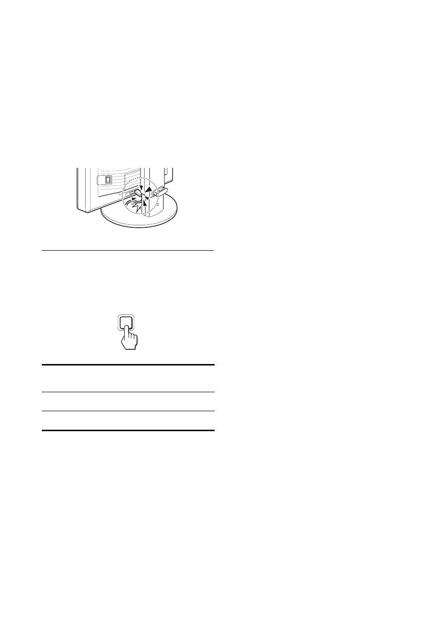
6
Remove the stopper pin after raising the height
adjustable stand straight.
Note
Do not remove the stopper pin while the stand is laid. It may fall or injure
you by the stand neck coming off from the Stand Base impetuously.
x
When using VESA Stand
You can attach a VESA stand in other brand by removing the
supplied stand attached to the display.
Setup 2: Connect the video signal
cables
1 Slide down the connector cover.
2 Tilt the display up.
And then move the display’s angle higher.
1
Stand Base
2
Screw
Stopper Pin
Screws
compatible with
VESA stand (4)
• Turn off the display and computer before connecting.
Notes
• Do not touch the pins of the video signal cable connector as this
might bend the pins.
• Check the alignment of the connector to avoid bending the pins of
the video signal cable connector.
Connector cover
8
p y
AEP.fm
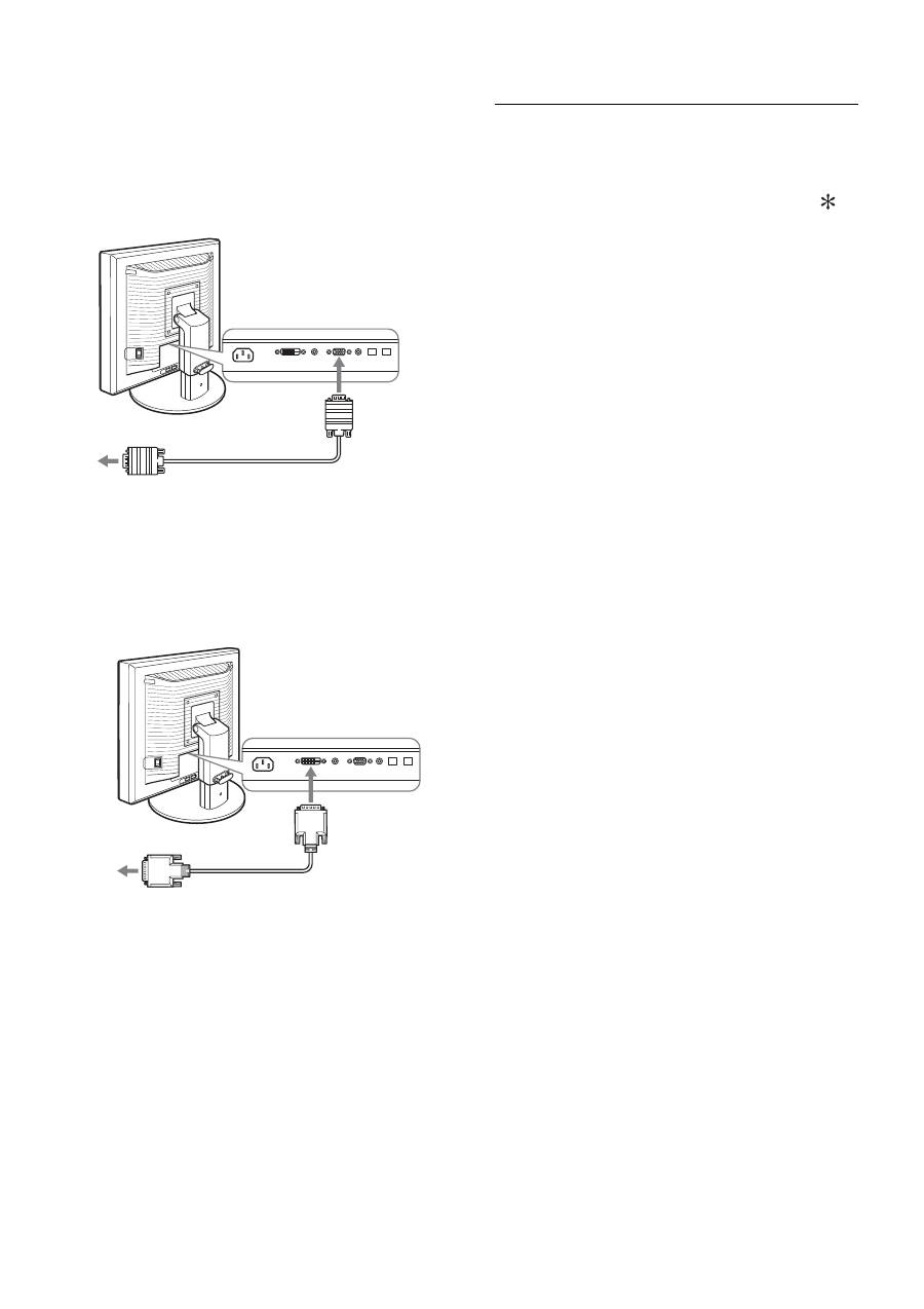
3 Connect the video signal cables to the display.
x
Connect a computer equipped with an HD15
output connector (analog RGB)
Using the supplied HD15-HD15 video signal cable (analog
RGB), connect the computer to the display’s HD 15 input
connector (analog RGB).
x
Connect a computer equipped with a DVI
output connector (digital RGB)
Using the supplied DVI-D video signal cable (digital RGB),
connect the computer to the display’s DVI-D input connector
(digital RGB).
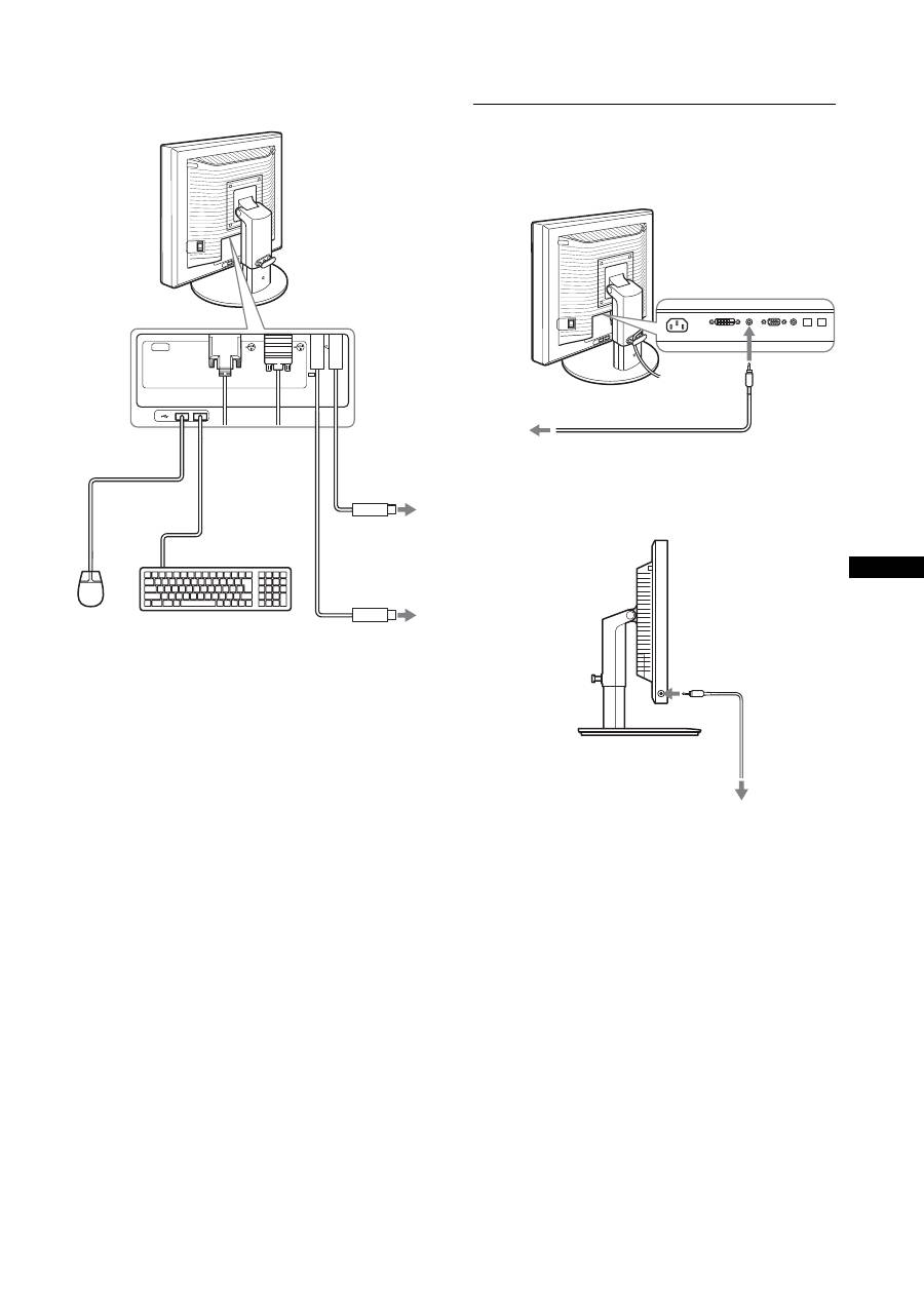
Setup 3: Connect the USB mouse
or the USB keyboard or
other devices (USB port-
equipped models only)
By connecting the USB mouse or the USB keyboard or other
devices, you can switch inputs back and forth (KVM function).
For more details, see “KVM function” (page 17).
If you are not using the USB mouse or the USB keyboard or other
devices on your display, go to Setup 4.
1
Connect the supplied cable between the display and
the computer.
2
Connect the USB mouse or the USB keyboard or
other devices to the display.
For Macintosh User:
If you connect the USB Downstream port to a Macintosh
keyboard with a power button, the power button on the
keyboard may fail to turn on. Turn on the power button on
your computer or connect the keyboard directly to your
computer and turn it on, and then connect the USB
Downstream port to the keyboard.
Notes
• The USB port of this display is compatible with Windows 2000 /
Windows XP Professional / Windows XP Home edition / Macintosh.
• If the USB mouse or the USB keyboard or other devices have already
connected to your computer, remove them once.
• This Setup is only designed for those computers and OS that are USB
compatible. For more details, refer to the operating instruction of your
computer or OS.
to the computer’s HD15 output
connector (analog RGB)
HD15-HD15 video signal
cable (analog RGB)
(supplied)
to the HD 15 input
connector (analog
RGB)
to the computer’s DVI output
connector (digital RGB)
DVI-D video signal cable
(digital RGB) (supplied)
to the DVI-D input
connector (digital RGB)
9
GB
p y
AEP.fm
Setup 4: Connect the audio cords
Connect the display’s audio input jack and audio
output jack of the computer or other audio equipment
using the supplied audio cord.
x
When you hear sound with your headphones
Connect the audio cable (not supplied) securely to the
display’s headphone jack.
Audio output will be changed when the display’s audio input and
audio output connection has been completed.
Using the display-speakers or headphones, you can also listen to
sound from your computer or other audio equipment connected to
the display-audio input jacks. For more details, see “Controlling
the volume” on page 16.
AC IN
DVI-D
HD15
1
2
2
1
To USB port to
Computer
To USB port to
Computer
USB cable
(supplied)
USB cable (supplied)
USB Mouse
USB
keyboard
2
2
1
1
to the audio
input
to audio output of
the computer or
other audio
equipment
audio cord (supplied)
to the headphone jack
audio cable
(not supplied)
10
p y
AEP.fm
Setup 5: Connect the power cord
1
Connect the supplied power cord securely to the
display’s AC IN connector.
2
Connect the other end securely to a power outlet.
Setup 6: Secure the cords and
close the connector cover
1
Draw the cords and cables through the cable holder
as illustrated.
2
Close the connector cover.
Note
When bounding the cords and cables, be sure to loosen them a little. If
they get pulled hard they may come off from the connectors/plugs as you
adjust the screen angle. If you stretch the cords and cables too hard they
may get damaged.
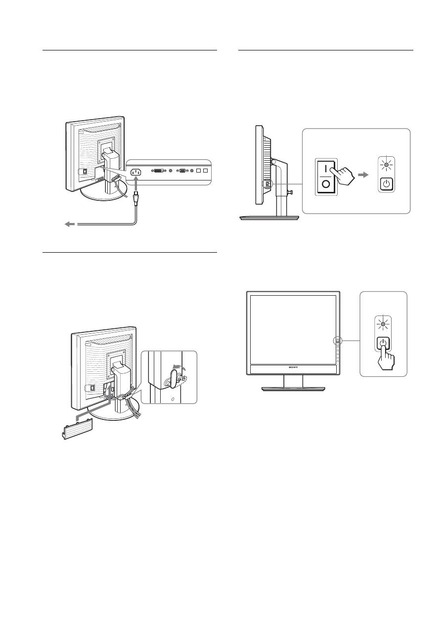
Setup 7: Turn on the display and
computer
1
Make sure that the
1
(power) Indicator blinks red. At
the time of your purchase, the MAIN POWER switch
is set to the
\
side.
Note
When the MAIN POWER switch on the right side of your display is not
set to the
\
side, press the
\
side and check that the
1
(power) indicator
blinks red.
2
Press the
1
(power) switch located on the front
right of the display.
The
1
(power) indicator lights up in green.
3
Turn on the computer.
to AC IN
to a power outlet
power cord (supplied)
1
2
MAIN POWER
lights in red
lights in green
11
GB
p y
AEP.fm
If no picture appears on your screen
• Check that the power cord and the video signal cables are
properly connected.
• If “NO INPUT SIGNAL”
appears on the screen:
– The computer is in the power saving mode. Try pressing any
key on the keyboard or moving the mouse.
– Check that the input signal setting is correct by pressing the
OK button (page 11).
• If “CABLE DISCONNECTED”
appears on the screen:
– Check that the video signal cables are properly connected.
– Check that the input signal setting is correct by pressing the
OK button (page 11).
•
If “OUT OF RANGE”
appears on the screen:
Reconnect the old display. Then adjust the computer’s graphics
board within the following ranges.
For more information about the on-screen messages, see “Trouble
symptoms and remedies” on page 19.
No need for specific drivers
The display complies with the “DDC” Plug & Play standard and
automatically detects all the display’s information. No specific driver
needs to be installed to the computer.
The first time you turn on your computer after connecting the display, the
setup Wizard may appear on the screen. If this is the case, follow the on-
screen instructions. The Plug & Play display is automatically selected so
that you can use this display.
The vertical frequency turns to 60 Hz.
Since flickers are unobtrusive on the display, you can use it as is. You do
not need to set the vertical frequency to any particular high value.
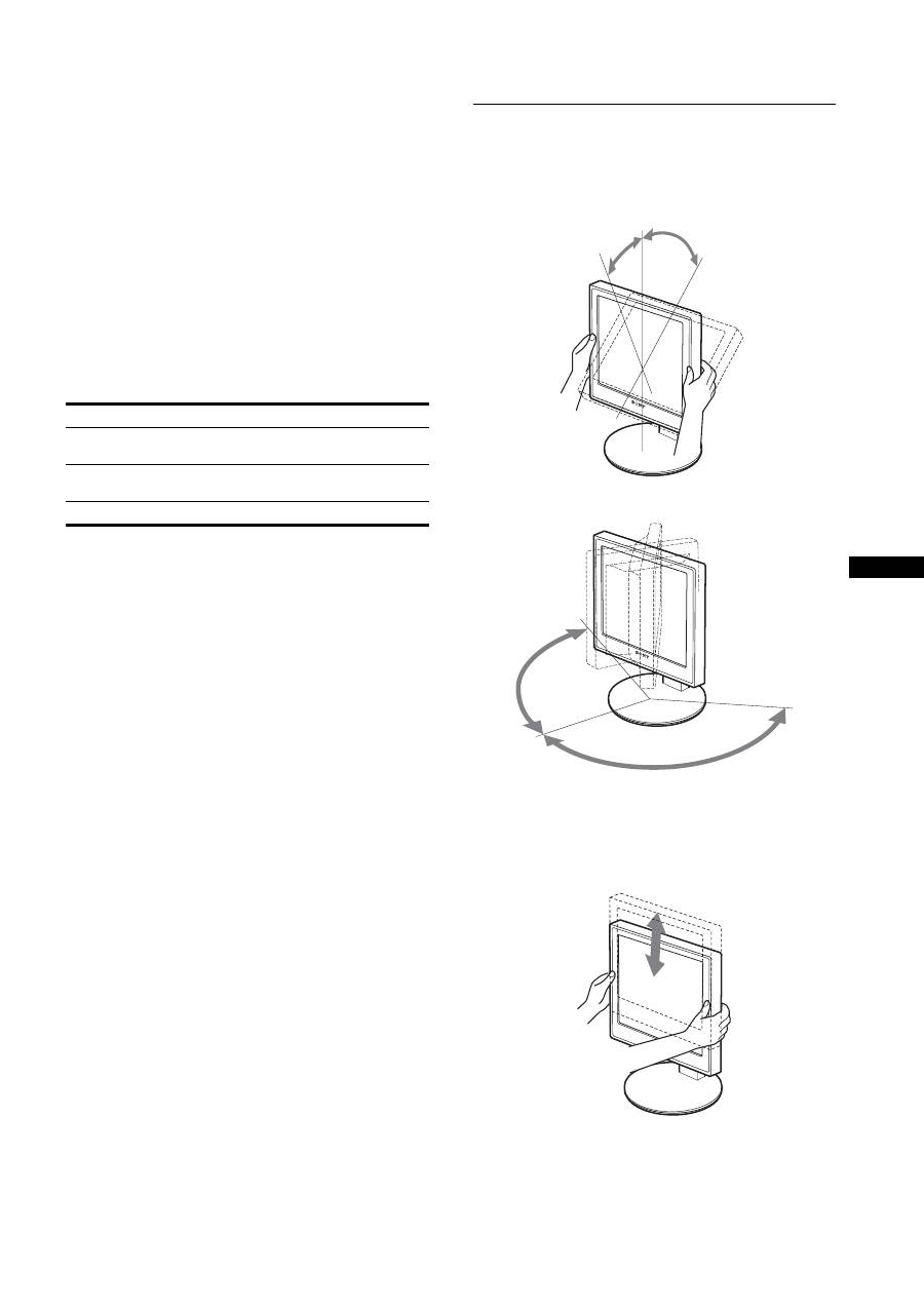
Setup 8: Adjust the tilt and height
This display can be adjusted within the angles shown below.
Hold both sides of the LCD display, then adjust display
angles.
When you use the height adjustable stand, the height adjust is also
available as below.
Hold both sides of the LCD display, and then adjust the
display height.
Analog RGB
Digital RGB
Horizontal
frequency
28–80 kHz
28–64 kHz
Vertical
frequency
48–75 Hz
60 Hz
Resolution
1280
×
1024 or less
approx. 5°
approx. 20°
approx. 175°
approx.
175°
approx. 110 mm
(4
11
/
32
inches)
12
p y
AEP.fm
To use the display comfortably
Adjust the viewing angle of your display according to the height
of your desk and chair so that light is not reflected from the
display to your eyes.
Notes
• When you adjust the display position, do not crash the display or cables
or other USB devices against objects around it. Be sure to move the
display quietly.
• Do not put any objects under the display when you adjust the height of
stand. It may get damaged by accident.
• When connecting USB products or USB devices to the display, be sure
not to crash them against the Stand Base. As adjusting the tilt and
height of the display, the display might get damaged depending on the
size of the products or devices. (USB port-equipped models only)
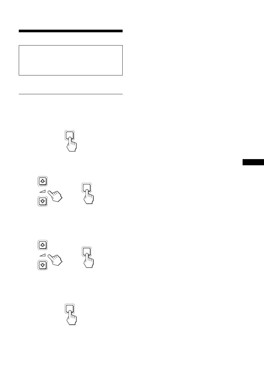
Selecting the input signal (INPUT1/
INPUT2)
Press the OK button.
The input signal changes every time you press the OK button.
On-screen message
(Appears about 5 seconds on
the upper left corner.)
Input signal configuration
INPUT1 : DVI-D
DVI-D input connector
(digital RGB) for INPUT1
INPUT2 : HD15
HD15 input connector
(analog RGB) for INPUT2
INPUT
OK
13
GB
p y
AEP.fm
Customizing Your Display
You can make numerous adjustments to your display using the
on-screen menu.
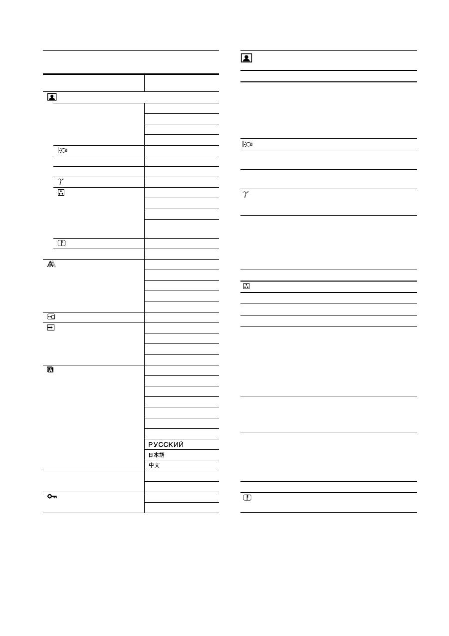
Navigating the menu
1
Display the main menu.
Press the MENU button to display the main menu on your
screen.
2
Select the menu you want to adjust.
Press the
m
/
M
buttons to display the desired menu. Press the
OK button to select the menu item.
3
Adjust the item.
Press the
m
/
M
buttons to make an adjustment, then press the
OK button.
When you press the OK button, the setting is stored, then the
display returns to the previous menu.
4
Close the menu.
Press the MENU button once to return to normal viewing. If
no buttons are pressed, the menu closes automatically after
about 45 seconds.
x
Resetting the adjustments to the default
settings
You can reset the adjustments using the RESET menu. For more
information about resetting the adjustments, see
0
(RESET) on
page 15.
Before making adjustments
Connect the display and the computer, and turn them on.
For the best results, wait for at least 30 minutes before making
any adjustments after display is connected to the computer and
turned on.
MENU
INPUT
OK
,
INPUT
OK
,
MENU
14
p y
AEP.fm
Menu options list
1)
When the ECO mode is set to “AUTO,” you cannot adjust
BACKLIGHT and CONTRAST.
2)
CONTRAST, BRIGHTNESS, and GAMMA are not adjustable when
“sRGB” selected.
PICTURE ADJUST menu
Notes
• If you select “sRGB,” you cannot adjust CONTRAST, BRIGHTNESS,
and GAMMA.
• When the ECO mode is set to "AUTO," you cannot adjust
BACKLIGHT and CONTRAST.
1)
If a computer or other equipment connected to the display is not sRGB-
compliant, color cannot be adjusted to the sRGB profile.
When you select “sRGB,” you cannot adjust CONTRAST,
BRIGHTNESS, and GAMMA.
If you have set the ECO mode to “AUTO,” you cannot select “sRGB.”
SDM-X75F/X95F
SDM-X75K/X95K
PICTURE ADJUST menu
MODE (ECO mode)
HIGH
MIDDLE
LOW
AUTO
1)
BACKLIGHT
;
1)
6
CONTRAST
;
1) 2)
8
BRIGHTNESS
;
2)
GAMMA
;
2)
COLOR
9300K
6500K
sRGB
2)
USER (GAIN and
BIAS)
SHARPNESS
;
0
MODE RESET
;
SCREEN
AUTO
PHASE
PITCH
H CENTER
V CENTER
MENU POSITION
;
INPUT SENSING
AUTO ON
INPUT1
INPUT2
AUTO OFF
LANGUAGE
ENGLISH
FRANÇAIS
DEUTSCH
ESPAÑOL
ITALIANO
NEDERLANDS
SVENSKA
0
RESET
OK
CANCEL
MENU LOCK
ON
OFF
Items
Press the
M
button Press the
m
button
MODE
Set the ECO mode.
Select the brightness of your display from
HIGH, MIDDLE, LOW, and AUTO to save
power consumption.
You can set a variety of mode by setting an
input.
HIGH
MIDDLE
LOW
AUTO
BACKLIGHT Brightens the screen. Darkens the screen.
6
CONTRAST
Sharpens the picture
contrasts.
Blurs the picture
contrasts.
8
BRIGHTNESS Brightens the picture
(Black level).
Darkens the picture
(Black level).
GAMMA
Features
You can adjust your pictures on the screen
to the original coloring.
Items
COLOR
Options
Features
9300K
Bluish hue
6500K
Reddish hue
sRGB
1)
When you select “sRGB” your coloring
is adjusted to the sRGB profile. (The
sRGB color setting is an industry-
standard color space protocol designed
for computer products.) When you select
“sRGB,” the color settings of your
computer must be set to the sRGB
profile.
USER
You can make additional adjustments to
lighter areas (GAIN: white level) and
darker areas (BIAS: black level). Also,
you can store the set color in memory.
Items
Press the
m
/
M
buttons
SHARPNESS
Adjust to sharpen the edge of images,
etc.
15
GB
p y
AEP.fm
SCREEN menu (analog RGB
signal only)
x
Automatic picture quality adjustment
function
When the display receives an input signal, it
automatically adjusts the picture’s position and
sharpness (phase/pitch). This ensures that a clear
picture appears on the screen (page 16).
Note
While the automatic picture quality adjustment function is activated, only
the
1
(power) switch is operable.
If the automatic picture quality adjustment function of
this display did not seem to adjust the picture
completely
You can make further automatic adjustment of the picture quality
for the current input signal. (See AUTO below.)
If you still need to make subtle adjustments to your
picture quality
You can manually adjust the picture’s sharpness (phase/pitch) and
position (horizontal/vertical position).
These adjustments are stored in memory and automatically
recalled when the display receives the same input signal. These
settings may have to be repeated if you change the input signal
after reconnecting your computer.
x
Adjust the picture’s sharpness and position
manually (PHASE/PITCH/H CENTER/V CENTER)
You can adjust the picture’s sharpness and position as follows.
1
Set the resolution to 1280 × 1024, on the computer.
2
Load the CD-ROM.
3
Start the CD-ROM and display the test pattern.
For Windows User
When Auto run operates:
1
Click “DISPLAY ADJUSTMENT TOOL (UTILITY).”
2
Click “Adjust” and confirm the resolution and then click
“Next”.
Test pattern for PITCH, PHASE, H CENTER and V
CENTER appears in order.
When Auto run fails to operate:
1
Open “My Computer” and right click the CD-ROM icon.
Go to “Explorer” and open the CD-ROM icon.
2
Open [Utility] and then select [Windows].
3
Start [Win_Utility.exe].
Test pattern appears.
For Macintosh user
1
Open [Utility] and then select [Mac].
2
Start [Mac_Utility.exe]
Test pattern appears.
MENU POSITION menu
INPUT SENSING menu
Those models of digital input search any input signals. You can
switch the signals back and forth automatically.
Items
0
MODE RESET
Options
Features
OK
You can reset BACKLIGHT,
CONTRAST, BRIGHTNESS,
GAMMA, COLOR, and SHARPNESS
to the default setting.
CANCEL
To cancel resetting and return to the
menu.
Items
Features
AUTO
Make the appropriate adjustments of the
screen’s phase, pitch and horizontal/
vertical position for the current input
signal and save them.
Items
Press the
m
/
M
buttons
PHASE
Minimize the horizontal stripes on the
screen.
PITCH
Vertical stripes become vanished.
H CENTER
Adjust the picture position when your
picture does not appear on the center of
the screen.
V CENTER
Items
Press the
m
/
M
buttons
MENU POSITION
You can change the menu displayed
position on the screen. You can choose
one of 9 positions.
Items
Features
AUTO ON
When the selected input has no signal, or
when you select an input with the OK
button and if it has no input signal, an
on-screen message appears (page 18).
Then the display checks the input signal
and switch to other input automatically.
When an input is changed, the selected
input is displayed on the upper left
corner of the screen.
When there still is no input signal, the
display goes into the power saving mode.
INPUT 1
When turning on the display, INPUT1 or
INPUT2 will be displayed as priority
setting (INPUT SENSING will not
function).
INPUT 2
AUTO OFF
The input is not changed automatically.
Press the OK button to change the input.
16
p y
AEP.fm
LANGUAGE menu
0
RESET menu (reset to the
default setting)
MENU LOCK menu
Technical Features
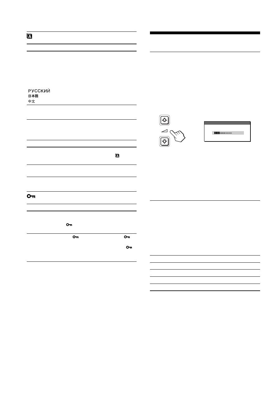
Controlling the volume
Using the display’s speakers or headphones, you can listen to
sound from your computer or other audio equipment connected to
the display’s audio input jacks.
You can control the volume by using a separate “Volume” menu
from the main menu.
1
Press the
m
/
M
buttons when no menu appears on
the screen.
2
Press the
m
/
M
buttons to control the volume.
The menu automatically disappears after about 5 seconds.
Notes
• You cannot adjust the volume when the main menu is displayed on the
screen.
• When your display is in power saving mode, no sound comes out of the
speakers or the headphones.
Power saving function
This display meets the power saving guidelines set by VESA,
E
NERGY
S
TAR, and NUTEK. If the display is connected to a
computer or video graphics board that is DPMS (Display Power
Management Standard) for Analog input / DMPM (DVI Digital
Monitor Power Management) for Digital input compliant, the
display will automatically reduce power consumption as shown
below.
1)
When your computer enters the “active off” mode, the input signal is
cut and NO INPUT SIGNAL appears on the screen. After 5 seconds,
the display enters the power saving mode.
“deep sleep” is the power saving mode defined by the Environmental
Protection Agency.
Items
Press the
m
/
M
buttons
ENGLISH
FRANÇAIS
DEUTSCH
ESPAÑOL
ITALIANO
NEDERLANDS
SVENSKA
French
German
Spanish
Italian
Dutch
Swedish
Russian
Japanese
Chinese
Items
Features
OK
To reset all the adjustment data to the
default setting except for the
(LANGUAGE) menu setting.
CANCEL
To cancel resetting and return to the
menu screen.
Items
Features
ON
Only the
1
(power) switch will operate.
If you attempt any other operation, the
(MENU LOCK) icon appears on the
screen.
OFF
Set
(MENU LOCK) to off. If
(MENU LOCK) has been set to ON,
when you press the MENU button,
(MENU LOCK) is automatically
selected.
Power mode
1
(power) indicator
normal operation
green
active off
1)
(deep sleep)
orange
power off
red
main power off
off
3 0
VO L U M E
,
