Sharp PN-V602: Supplied Components
Supplied Components: Sharp PN-V602
ENGLISH
5
E
Supplied Components
If any component should be missing, please contact your dealer.
Liquid Crystal Display Monitor: 1
Protection cover: 4
Cableclamp:2
Handle screw (short): 4
Power cord: 1
Bezelsheet(long/short):2each
CD-ROM(UtilityDiskforWindows):1
Bezelsheetattachmentinstructions:1
Setup manual (this manual): 1
* Sharp Corporation holds authorship rights to the Utility Disk program. Do not reproduce it without permission.
* For environmental protection!
Do not dispose of batteries in household waste. Follow the disposal instructions for your area.
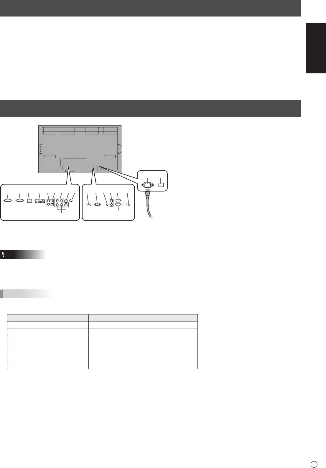
Connections
1. PC/AV HDMI input terminal
2. PC D-sub input terminal
3. Audio input terminal
4. Audio output terminals
5. RS-232C output terminal
6. RS-232C input terminal
7. Control kit terminal
8. PC/AV DVI-D input terminal
9. PC/AV DVI-D output terminal
10. LAN terminal
11. External speaker terminals
12. Audio1 input terminals
13. Audio2 input terminals
14. PC RGB input terminals
15. AV component input terminals
16. AV video input terminal
17. AV S-video input terminal
18. AC input terminal
19. Main power switch
20. Power cord (Supplied)
Caution
• Besuretoturnoffthemainpowerswitchanddisconnecttheplugfromthepoweroutletbeforeconnecting/disconnecting
cables. Also, read the manual of the equipment to be connected.
• Becarefulnottoconfusetheinputterminalwiththeoutputterminalwhenconnectingcables.Accidentallyreversingcables
connected to the input and output terminals may cause malfunctions and the other problems.
TIPS
• SettheaudioinputterminalusedforeachinputmodeinAUDIOSELECTontheOPTIONmenu.Thefactorysettingsare
shown below.
Input mode Audio input terminal (Factory setting)
PCD-SUB,PCDVI-D,PCRGB
Audio input terminal
AVDVI-D Audio1 input terminal
AV COMPONENT(BNC),
Audio2inputterminal
AVS-VIDEO, AV VIDEO(BNC)
AV COMPONENT(D-SUB),
Audio input terminal
AV VIDEO(D-SUB)
PC HDMI, AV HDMI PC/AV HDMI input terminal
• Whenconnectingtheexternalspeaker,attachthespeakercablecore(includedintheoptionalPN-ZB02).
• HDMI,theHDMIlogoandHigh-DenitionMultimediaInterfacearetrademarksorregisteredtrademarksofHDMILicensing
LLC.
When the PN-ZB02 (optional)
18 19
is attached
11109812345 712
1413 1716
20
6
15
For power
outlet
E
6
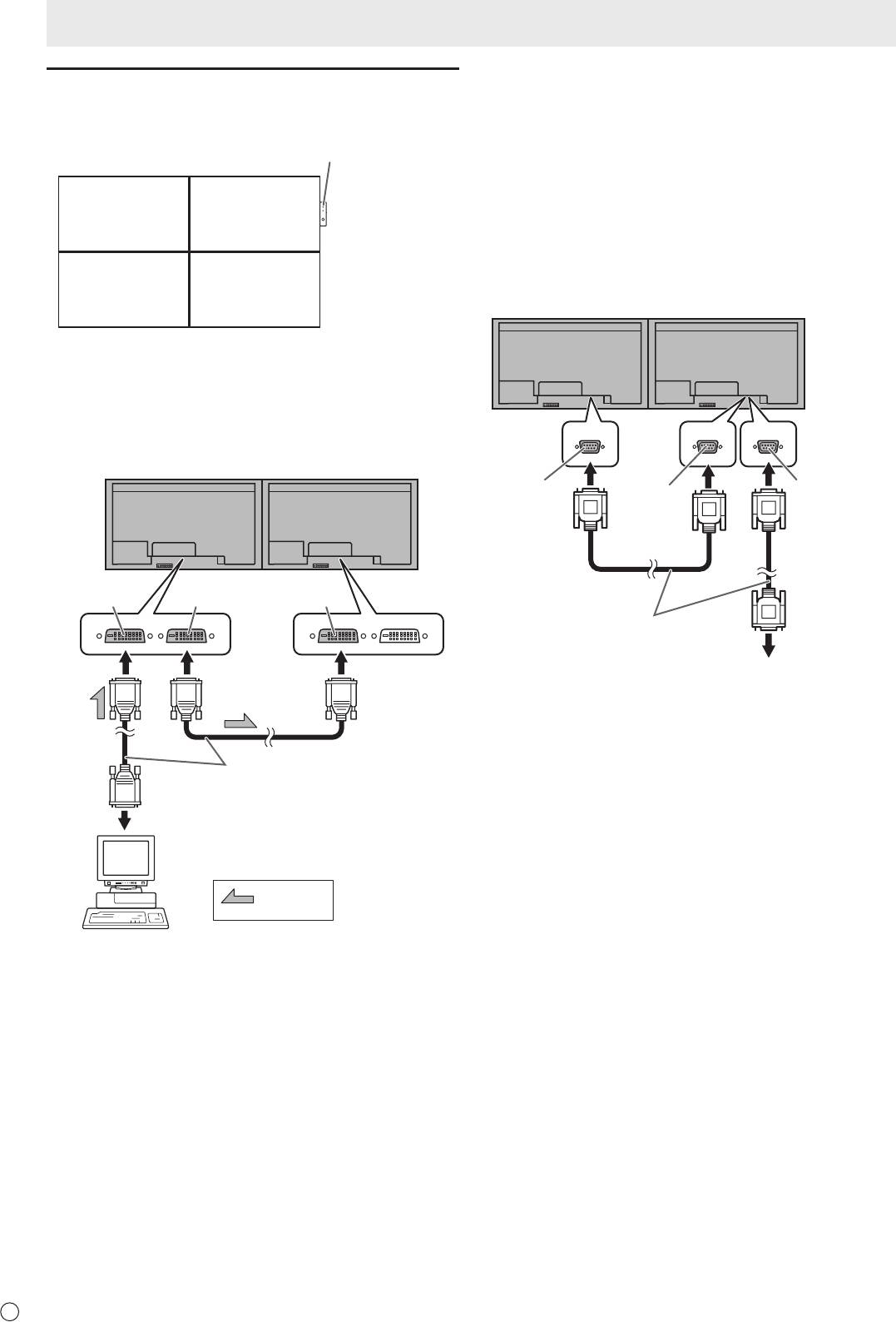
Multiple monitor connection
[Example]
Remote control sensor box
(Supplied with the PN-ZR01 (optional))
Second monitor
First monitor
Secondary
Primary
(Expansion unit)
(Main unit)
ID No.: 2
ID No.: 1
Third monitor
Fourth monitor
Secondary
Secondary
(Expansion unit)
(Expansion unit)
ID No.: 3
ID No.: 4
* Always install the remote control sensor box on the primary
monitor.
■ Connection with video cable
May vary depending on the system being used.
IfusingthePC/AVDVI-Dterminal,upto5monitorscanbe
connectedinadaisychain.(WhenthePN-ZB02isattached)
First monitor
Second monitor
PC/AV DVI-D
PC/AV DVI-D
PC/AV DVI-D
input terminal
output terminal
input terminal
Digital signal (DVI) cables
(commercially available)
To PC digital RGB output terminal
shows the
signal flow
Connections
■ Connection with RS-232 cable
IfyouconnectthemonitorinadaisychainusingRS-232
cable, using the monitor buttons on the primary (main unit),
settings are copied to the secondary (expansion unit) and
operation from the primary can perform operation for all
monitors. Setting each ID No. in the monitor is required.
Therstmonitorwillbesetasprimary(mainunit)andthe
second monitor and beyond will be secondaries (expansion
units).
ConnecttheRS-232Ccablesinorder,startingwiththerst
monitor (primary monitor). If monitors are connected in a
different order they may not be operable.
First monitor: primary
Second monitor: secondary
RS-232C
RS-232C
RS-232C
output terminal
input terminal
output terminal
RS-232 straight cable
(commercially available)
Third monitor: connects to secondary
RS-232C input terminal
Connect the third monitor and other monitors in the same
manner.
Upto25monitorscanbeconnected.(Dependingonthe
length of the cable used and the surrounding environment.)
ID Number is set with the primary monitor’s buttons. If you set
AUTO ASSIGN ID No., located in the menu of the monitor to
ON, the ID No. will be automatically assigned in order from the
primary.
ENGLISH
7
E
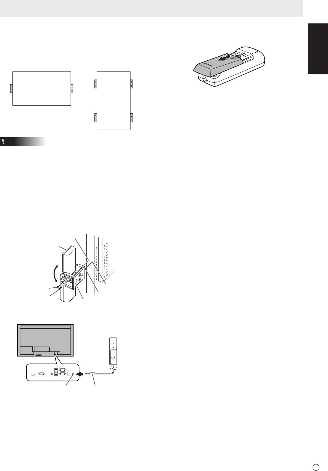
■ Connection with the control kit (optional)
If performing operation of the monitor with the remote control
unit,thePN-ZR01controlkit(optional)isrequired.
Attach the remote control sensor box as shown in the following
illustration. (Right side recommended)
For the monitor in
For the monitor in
landscape orientation
portrait orientation
Caution
• Whenattachingtheremotecontrolsensorbox,turnthe
main power switch OFF.
• ConnectthemonitorstogetherinadaisychainwithRS-232
cable.
1. Insert the anti-rotation protrusion of the mounting
bracket into the anti-rotation hole of the monitor.
2. Secure the stand angling hole of the monitor with the
mounting screw.
3. Adjust the angle of the remote control sensor box, and
secure it with the xing screw, so that it may accurately
receive signals from the remote control unit.
Stand angling hole
Remote control
sensor box
Angle
adjustment
Anti-rotation hole
Fixing screw
Anti-rotation protrusion
Mounting screw (short)
Mounting bracket
4. Insert the remote control sensor box connection cable
into the control kit terminal.
Remote control
sensor box
Connection cableControl kit terminal
Connections
Installing the batteries
1. Press the cover gently and slide it in the direction of the
arrow.
2. Seetheinstructionsinthecompartmentandputinthe
batteries(R-6(“AA”size)x2)(suppliedwiththePN-ZR01
(optional))withtheirplus(+)andminus(-)sidesoriented
correctly.
3. Close the cover.
Оглавление
- Contents
- SAFETY PRECAUTIONS
- SAFETY PRECAUTIONS (Continued)
- MOUNTING PRECAUTIONS
- Supplied Components
- Turning Power On/Off
- Table des matières
- PRÉCAUTIONS DE SÉCURITÉ
- PRÉCAUTIONS DE SÉCURITÉ (Suite)
- PRÉCAUTIONS POUR LE MONTAGE
- Composants fournis
- Mise sous tension et hors tension
- Índice
- PRECAUCIONES DE SEGURIDAD
- PRECAUCIONES DE SEGURIDAD (Continuación)
- PRECAUCIONES DE MONTAJE
- Componentes suministrados
- Encendido/apagado
- Inhalt
- SICHERHEITSVORKEHRUNGEN
- SICHERHEITSVORKEHRUNGEN (Fortsetzung)
- WICHTIGE HINWEISE ZUR BEFESTIGUNG
- Mitgelieferte Komponenten
- Ein- und ausschalten
- Содержание
- ПРАВИЛА ТЕХНИКИ БЕЗОПАСНОСТИ
- ПРАВИЛА ТЕХНИКИ БЕЗОПАСНОСТИ (Продолжение)
- МЕРЫ ПРЕДОСТОРОЖНОСТИ ПРИ КРЕПЛЕНИИ
- Комплектные принадлежности
- Включение/выключение питания


