Dell OptiPlex 320: Mini Tower Computer — Back-Panel Connectors
Mini Tower Computer — Back-Panel Connectors: Dell OptiPlex 320
Table of contents
- Notes, Notices, and Cautions
- Contents
- Finding Information What Are You Looking For? Find It Here
- What Are You Looking For? Find It Here
- What Are You Looking For? Find It Here
- Setting Up Your Computer Set Up Your Keyboard and Mouse
- Set Up Your Monitor
- Power Connections
- System Views Mini Tower Computer — Front View 3 floppy drive Insert a floppy disk into this drive.
- 9 headphone connector Use the headphone connector to attach headphones.
- Mini Tower Computer — Back View
- Mini Tower Computer — Back-Panel Connectors
- 7 microphone connector
- Desktop Computer — Front View
- Desktop Computer — Back View
- Desktop Computer — Back-Panel Connectors
- 9 video connector
- Removing the Computer Cover Before You Begin Before Working Inside Your Computer
- Mini Tower Computer
- 1 security cable slot
- Desktop Computer
- Inside Your Computer Mini Tower Computer
- System Board Components
- Jumper Settings Mini Tower Computer
- Jumper Setting Description Desktop Computer
- System Board Components
- Jumper Settings Desktop Computer
- Jumper Setting Description Solving Problems Dell Diagnostics When to Use the Dell Diagnostics
- Starting the Dell Diagnostics From Your Hard Drive Starting the Dell Diagnostics From the Drivers and Utilities CD
- Dell Diagnostics Main Menu Option Function Tab Function
- System Lights Power Light Problem Description Suggested Resolution
- Diagnostic Lights Light Pattern Problem Description Suggested Resolution
- Light Pattern Problem Description Suggested Resolution
- Light Pattern Problem Description Suggested Resolution
- Beep Codes Code Cause Code Cause
- Resolving Software and Hardware Incompatibilities Using Microsoft Windows XP System Restore Creating a Restore Point Restoring the Computer to an Earlier Operating State
- Undoing the Last System Restore Enabling System Restore Reinstalling Microsoft Windows XP Before You Begin
- Reinstalling Windows XP Booting From the Operating System CD
- Windows XP Setup
- Using the Drivers and Utilities CD Drivers for Your Computer
4 voltage selection switch Your computer is equipped with a manual voltage-selection switch. To avoid
damaging a computer with a manual voltage-selection switch, set the switch for the
voltage that most closely matches the AC power available in your location.
NOTICE: In Japan the voltage-selection switch must be set to the 115-V
position.
Also, ensure that your monitor and attached devices are electrically rated to operate
with the AC power available in your location.
5 back-panel connectors Plug serial, USB, and other devices into the appropriate connector.
See "Mini Tower Computer — Back-Panel Connectors" on page 14.
6 card slots Access connectors for any installed PCI and PCI Express cards.
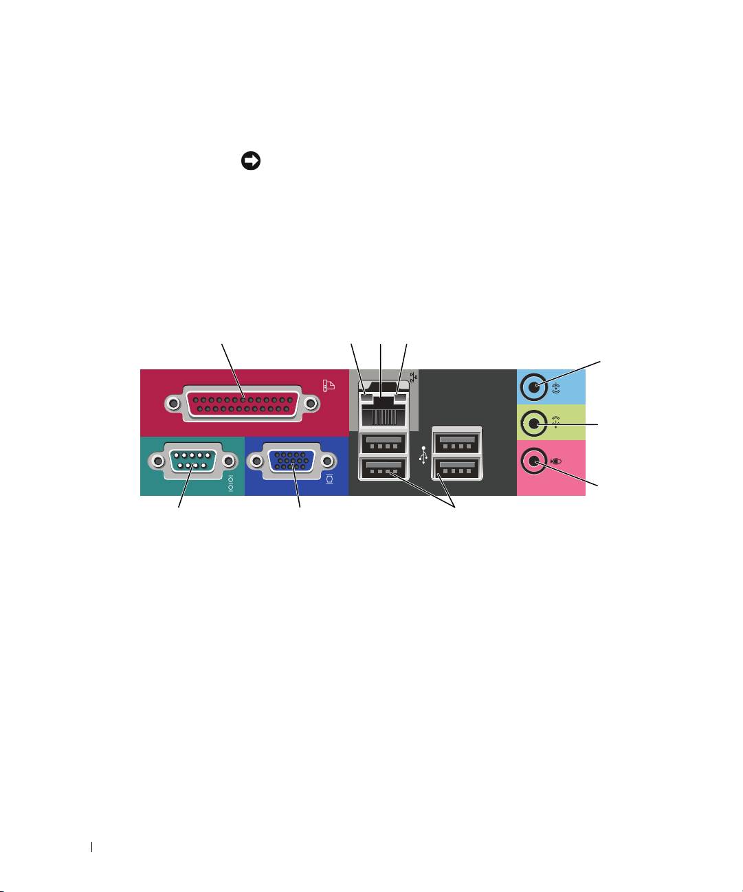
Mini Tower Computer — Back-Panel Connectors
13
24
5
6
7
10 9 8
1
parallel connector
Connect a parallel device, such as a printer, to the parallel connector. If you have a
USB printer, plug it into a USB connector.
NOTE: The integrated parallel connector is automatically disabled if the computer
detects an installed card containing a parallel connector configured to the same
address. For more information, see your online User’s Guide.
2
link integrity light • Green — A good connection exists between a 10-Mbps network and the
computer.
• Orange — A good connection exists between a 100-Mbps network and the
computer.
• Off — The computer is not detecting a physical connection to the network.
14 Quick Reference Guide
