Dell OptiPlex 320 – page 2
Manual for Dell OptiPlex 320
Table of contents
- Notes, Notices, and Cautions
- Contents
- Finding Information What Are You Looking For? Find It Here
- What Are You Looking For? Find It Here
- What Are You Looking For? Find It Here
- Setting Up Your Computer Set Up Your Keyboard and Mouse
- Set Up Your Monitor
- Power Connections
- System Views Mini Tower Computer — Front View 3 floppy drive Insert a floppy disk into this drive.
- 9 headphone connector Use the headphone connector to attach headphones.
- Mini Tower Computer — Back View
- Mini Tower Computer — Back-Panel Connectors
- 7 microphone connector
- Desktop Computer — Front View
- Desktop Computer — Back View
- Desktop Computer — Back-Panel Connectors
- 9 video connector
- Removing the Computer Cover Before You Begin Before Working Inside Your Computer
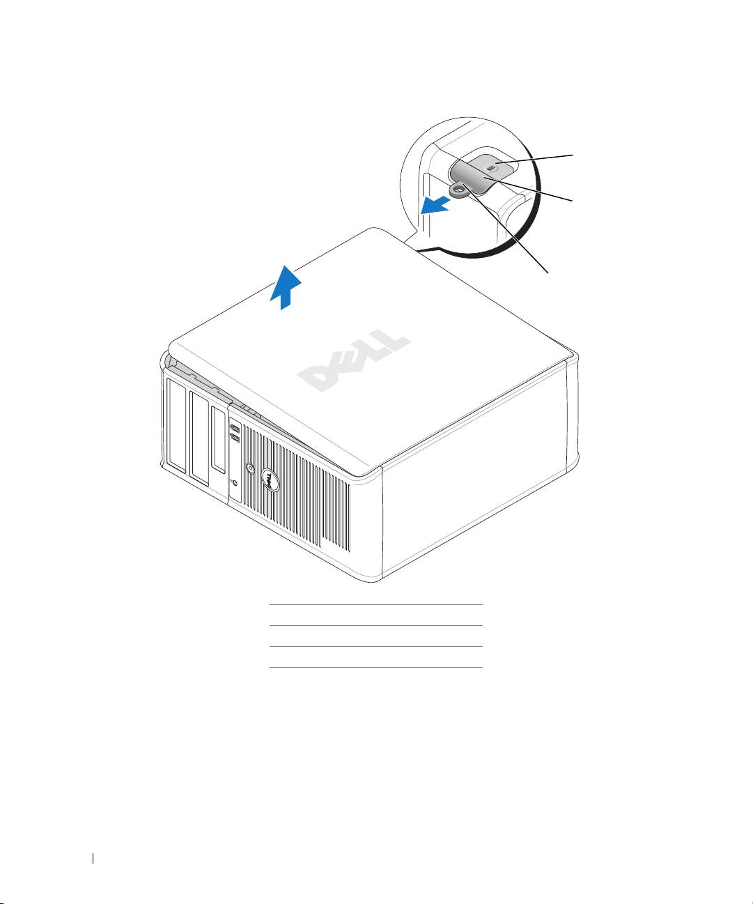
- Mini Tower Computer
- 1 security cable slot
- Desktop Computer
- Inside Your Computer Mini Tower Computer
- System Board Components
- Jumper Settings Mini Tower Computer
- Jumper Setting Description Desktop Computer
- System Board Components
- Jumper Settings Desktop Computer
- Jumper Setting Description Solving Problems Dell Diagnostics When to Use the Dell Diagnostics
- Starting the Dell Diagnostics From Your Hard Drive Starting the Dell Diagnostics From the Drivers and Utilities CD
- Dell Diagnostics Main Menu Option Function Tab Function
- System Lights Power Light Problem Description Suggested Resolution
- Diagnostic Lights Light Pattern Problem Description Suggested Resolution
- Light Pattern Problem Description Suggested Resolution
- Light Pattern Problem Description Suggested Resolution
- Beep Codes Code Cause Code Cause
- Resolving Software and Hardware Incompatibilities Using Microsoft Windows XP System Restore Creating a Restore Point Restoring the Computer to an Earlier Operating State
- Undoing the Last System Restore Enabling System Restore Reinstalling Microsoft Windows XP Before You Begin
- Reinstalling Windows XP Booting From the Operating System CD
- Windows XP Setup
- Using the Drivers and Utilities CD Drivers for Your Computer

2
Disconnect any telephone or telecommunication lines from the computer.
3
Disconnect your computer and all attached devices from their electrical outlets, and then press the
power button to ground the system board.
4
If applicable, remove the computer stand (for instructions, see the documentation that came with the
stand).
CAUTION: To guard against electrical shock, always unplug your computer from the electrical outlet before
removing the cover.
5
Remove the computer cover:
• Remove the mini tower computer cover (see "Mini Tower Computer" on page 21).
• Remove the desktop computer cover (see "Desktop Computer" on page 27).
NOTICE: Before touching anything inside your computer, ground yourself by touching an unpainted metal surface,
such as the metal at the back of the computer. While you work, periodically touch an unpainted metal surface to
dissipate any static electricity that could harm internal components.
Mini Tower Computer
CAUTION: Before you begin any of the procedures in this section, follow the safety instructions in the Product
Information Guide.
CAUTION: To guard against electrical shock, always unplug your computer from the electrical outlet before
removing the computer cover.
1
Follow the procedures in "Before You Begin" on page 20.
2
If you have installed a padlock through the padlock ring on the back panel, remove the padlock.
3
Lay the computer on its side.
4
Slide the cover release latch back as you lift the cover.
5
Grip the sides of the computer cover and pivot the cover up using the hinge tabs as leverage points.
6
Remove the cover from the hinge tabs and set it aside on a soft nonabrasive surface.
Quick Reference Guide 21
1
2
3
1 security cable slot
2 cover release latch
3 padlock ring
22 Quick Reference Guide
Desktop Computer
CAUTION: Before you begin any of the procedures in this section, follow the safety instructions in the Product
Information Guide.
CAUTION: To guard against electrical shock, always unplug your computer from the electrical outlet before
removing the computer cover.
1
Follow the procedures in "Before You Begin" on page 20.
2
If you have installed a padlock through the padlock ring on the back panel, remove the padlock.
3
Slide the cover release latch back as you lift the cover.
4
Pivot the cover up using the hinge tabs as leverage points.
5
Remove the cover from the hinge tabs and set it aside on a soft nonabrasive surface.
1
2
3
1
security cable slot
2
cover release latch
3
padlock ring
Quick Reference Guide 23
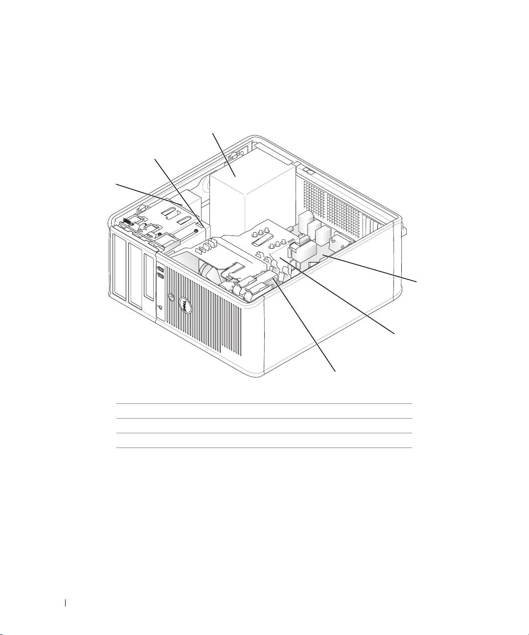
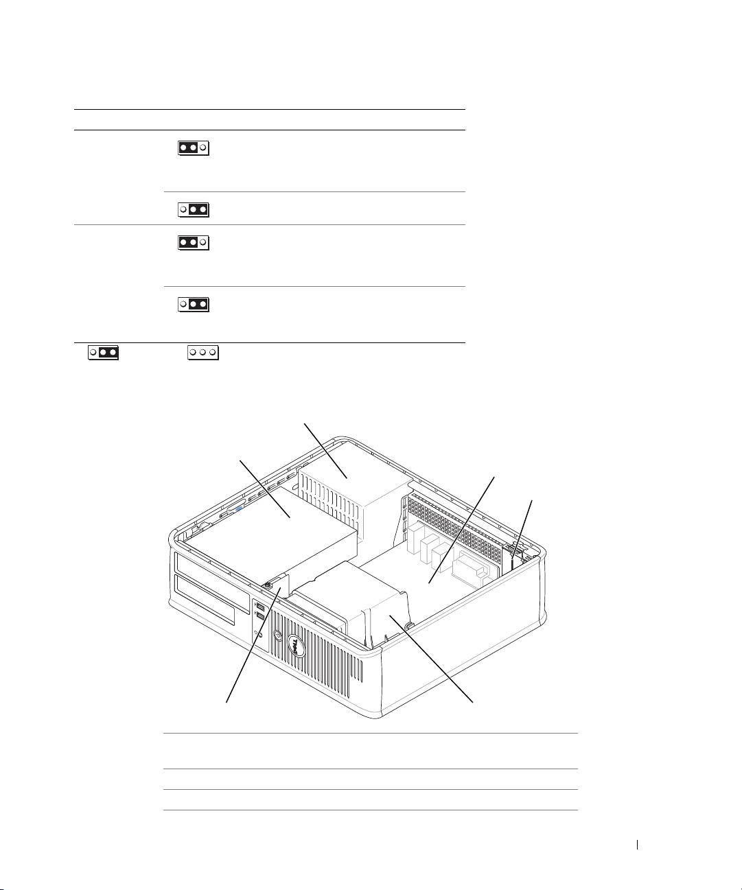
Inside Your Computer
Mini Tower Computer
3
2
1
4
5
6
1 CD/DVD drive 4 system board
2 floppy drive 5 heat sink assembly
3 power supply 6 hard drive
24 Quick Reference Guide
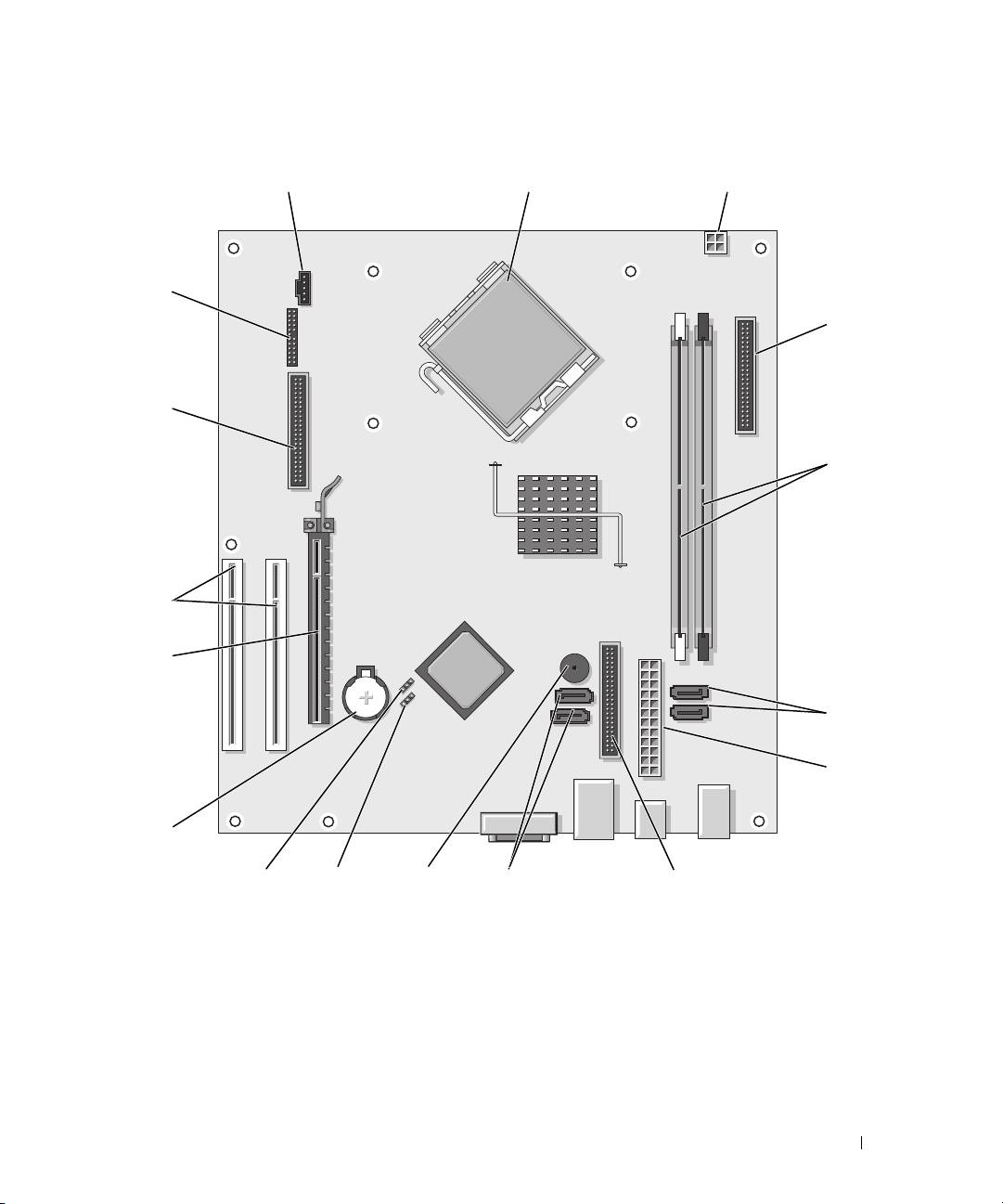
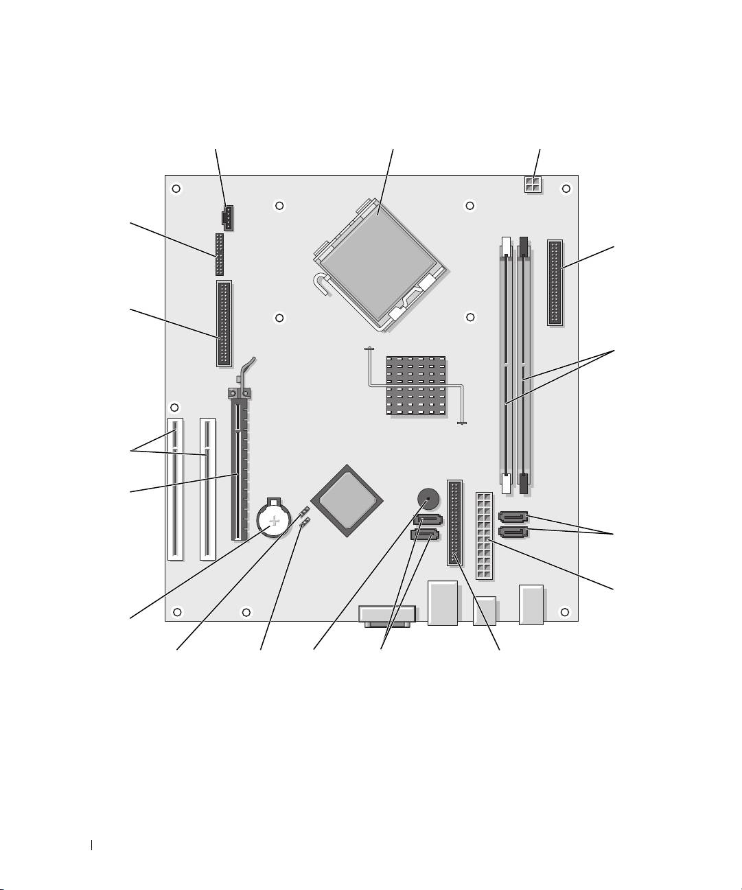
System Board Components
12
3
17
4
16
5
15
14
6
7
13
12
10
911
8
Quick Reference Guide 25
1 fan connector (FAN) 10 internal buzzer (SPKR1)
2 processor connector (CPU) 11 password jumper (PSWD)
3 processor power connector (12VPOWER) 12 real time clock reset jumper (RTCRST)
4 front-panel connector (FNT_PANEL) 13 battery socket (BATT)
5 memory module connectors (DIMM_1,
14 PCI Express x16 card connector
DIMM_2)
6 SATA drive connectors (SATA0, SATA1) 15 PCI card connectors (2)
7 power connector (POWER) 16 floppy drive connector (FLOPPY)
8 CD/DVD drive connector (IDE) 17 serial/ PS/2 connector (PS2/SER2)
9 SATA drive connectors (SATA2, SATA3)
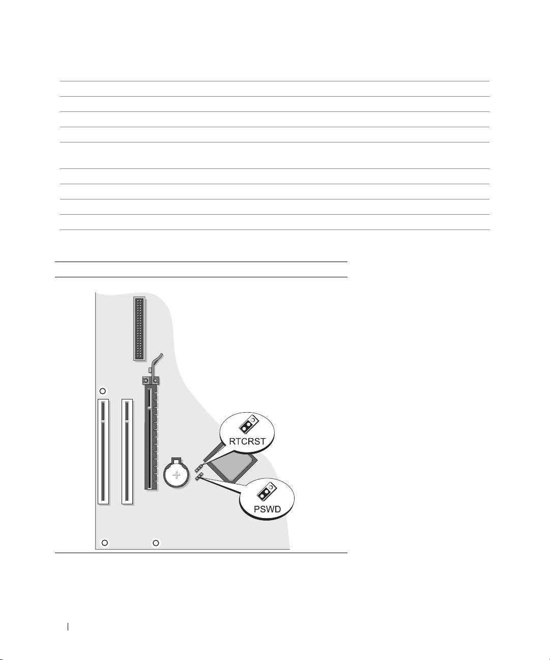
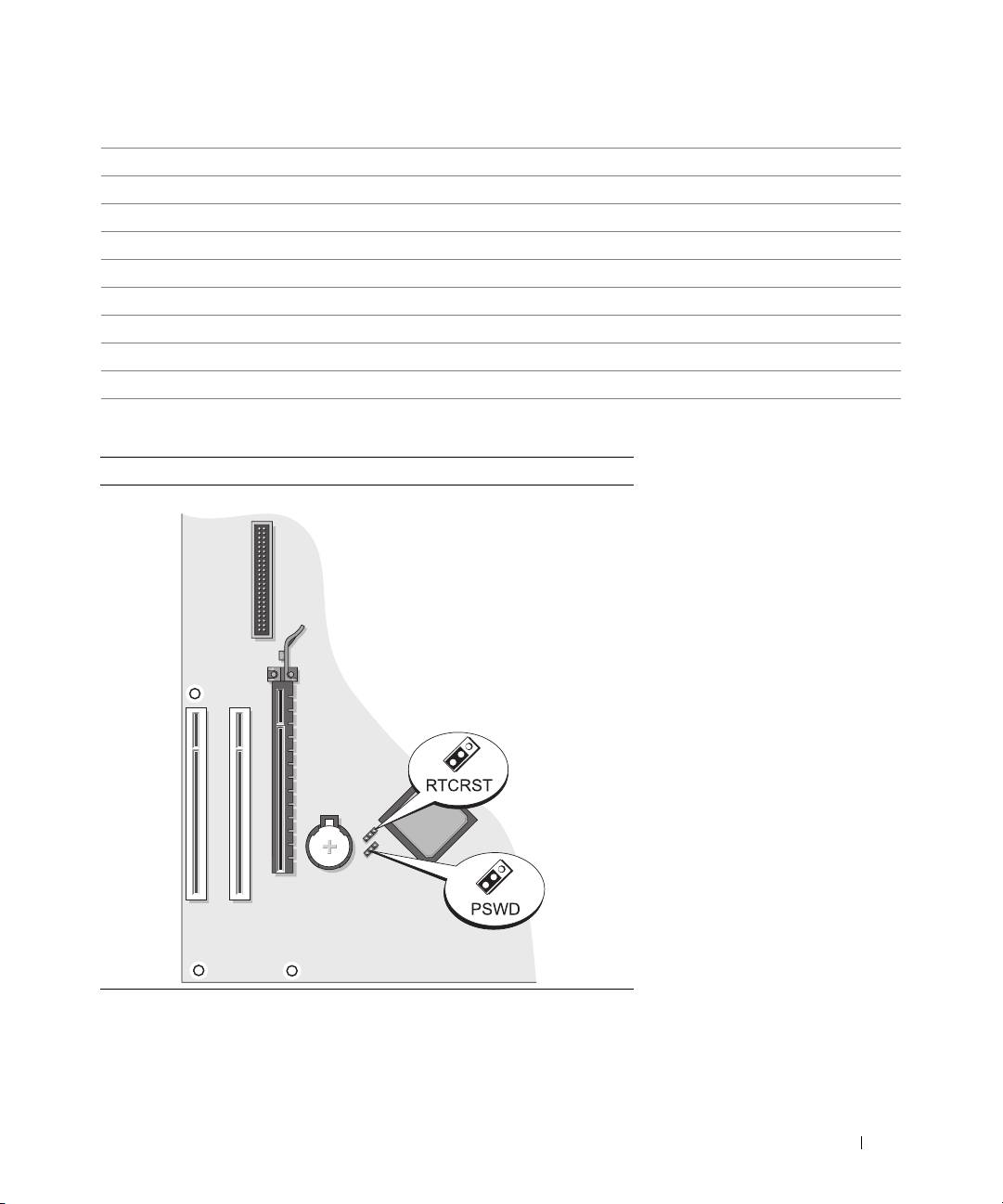
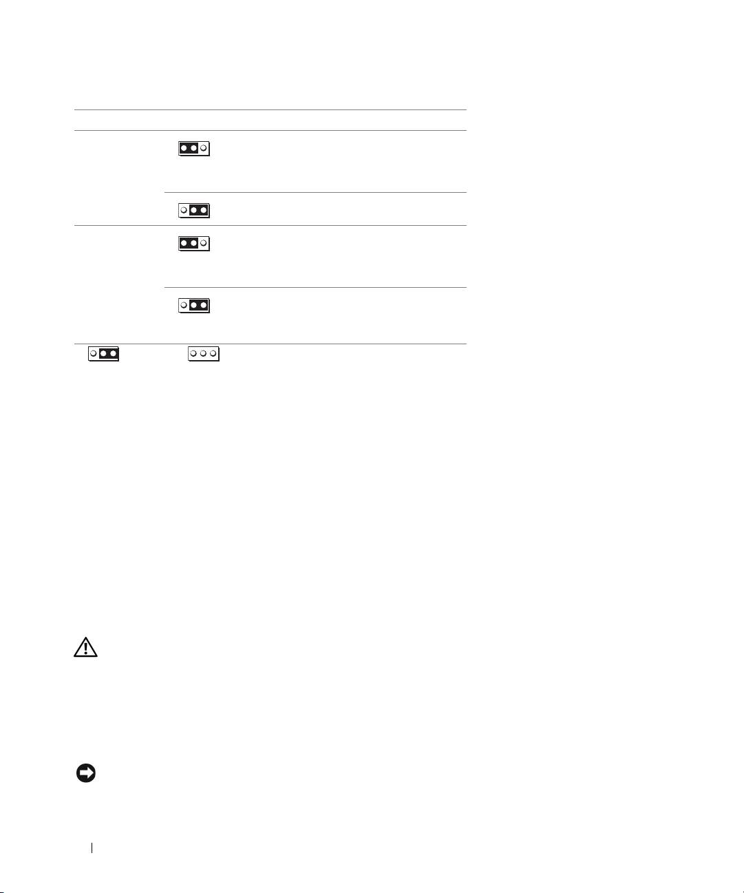
Jumper Settings
Mini Tower Computer
26 Quick Reference Guide
Jumper Setting Description
PSWD Password features are enabled
(default setting).
1
Password features are disabled.
RTCRST
The real-time clock has been
enabled (default setting).
1
The real-time clock is being reset
(jumpered temporarily).
jumpered unjumpered
Desktop Computer
2
1
3
4
6
5
1 drive bay (CD/DVD, floppy,
4 card slots
and hard drive)
2 power supply 5 heat sink assembly
3 system board 6 front I/O panel
Quick Reference Guide 27
System Board Components
12
3
17
4
16
5
15
14
6
7
13
12
11 9
10
8
28 Quick Reference Guide
1 fan connector (FAN) 10 internal buzzer (SPKR1)
2 processor connector (CPU) 11 password jumper (PSWD)
3 processor power connector (12VPOWER) 12 RTC reset jumper (RTCRST)
4 front-panel connector (FNT_PANEL) 13 battery socket (BATT)
5 memory module connectors (DIMM_1, DIMM_2) 14 PCI Express x16 card connector
6 serial ATA drive connectors (SATA0, SATA1) 15 PCI card connector (2)
7 power connector (POWER) 16 floppy drive connector (FLOPPY)
8 CD/DVD drive connector (IDE) 17 serial/ PS/2 connector (PS2/SER2)
9 serial ATA drive connectors (SATA2, SATA3)
Jumper Settings
Desktop Computer
Quick Reference Guide 29
Jumper Setting Description
PSWD Password features are enabled
(default setting).
1
Password features are disabled.
RTCRST
The real-time clock has been
enabled (default setting).
1
The real-time clock is being reset
(jumpered temporarily).
jumpered unjumpered
Solving Problems
Dell provides a number of tools to help you if your computer does not perform as expected. For the latest
troubleshooting information available for your computer, see the Dell Support website at
support.dell.com.
If computer problems occur that require help from Dell, write a detailed description of the error, beep
codes, or diagnostics light patterns, record your Express Service Code and Service Tag below, and then
contact Dell from the same location as your computer. For information on contacting Dell, see your
online User’s Guide.
For an example of the Express Service Code and Service Tag, see "Finding Information" on page 5.
Express Service Code: ___________________________
Service Tag: ___________________________
Dell Diagnostics
CAUTION: Before you begin any of the procedures in this section, follow the safety instructions in the Product
Information Guide.
When to Use the Dell Diagnostics
If you experience a problem with your computer, perform the checks in "Solving Problems" in your online
User’s Guide and run the Dell Diagnostics before you contact Dell for technical assistance. For
information on contacting Dell, see your online User’s Guide.
NOTICE: The Dell Diagnostics works only on Dell™ computers.
30 Quick Reference Guide

Enter system setup (see "System Setup" in your online User’s Guide for instructions), review your
computer’s configuration information, and ensure that the device you want to test displays in system
setup and is active.
Start the Dell Diagnostics from either your hard drive or from the optional Drivers and Utilities CD (also
known as the ResourceCD).
Starting the Dell Diagnostics From Your Hard Drive
1
Turn on (or restart) your computer.
2
When the DELL logo appears, press <F12> immediately.
NOTE: If you see a message stating that no diagnostics utility partition has been found, run the Dell
Diagnostics from the optional Drivers and Utilities CD (see "Starting the Dell Diagnostics From the Drivers and
Utilities CD" on page 31).
If you wait too long and the operating system logo appears, continue to wait until you see the
®
®
Microsoft
Windows
desktop. Then shut down your computer and try again.
3
When the boot device list appears, highlight
Boot to Utility Partition
and press <Enter>.
4
When the Dell Diagnostics
Main Menu
appears, select the test you want to run.
Starting the Dell Diagnostics From the Drivers and Utilities CD
1
Insert the
Drivers and Utilities
CD.
2
Shut down and restart the computer.
When the DELL logo appears, press <F12> immediately.
If you wait too long and the operating system logo appears, continue to wait until you see the
Microsoft Windows desktop. Then shut down your computer and try again.
NOTE: The next steps change the boot sequence for one time only. On the next start-up, the computer boots
according to the devices specified in system setup.
3
When the boot device list appears, highlight the listing for the CD/DVD drive and press <Enter>.
4
Select the listing for the CD/DVD drive option from the CD boot menu.
5
Select the option to boot from the CD/DVD drive from the menu that appears.
6
Ty p e
1
to start the
Drivers and Utilities
CD menu.
7
Ty p e
2
to start the Dell Diagnostics.
8
Select
Run the 32 Bit Dell Diagnostics
from the numbered list. If multiple versions are listed, select
the version appropriate for your computer.
9
When the Dell Diagnostics
Main Menu
appears, select the test you want to run.
Quick Reference Guide 31

Dell Diagnostics Main Menu
1
After the Dell Diagnostics loads and the
Main
Menu
screen appears, click the button for the option
you want.
Option Function
Express Test Performs a quick test of devices. This test typically takes 10 to 20 minutes and requires
no interaction on your part. Run Express Test first to increase the possibility of tracing
the problem quickly.
Extended Test Performs a thorough check of devices. This test typically takes an hour or more and
requires you to answer questions periodically.
Custom Test Tests a specific device. You can customize the tests you want to run.
Symptom Tree Lists the most common symptoms encountered and allows you to select a test based on
the symptom of the problem you are having.
2
If a problem is encountered during a test, a message appears with an error code and a description of the
problem. Write down the error code and problem description and follow the instructions on the
screen.
If you cannot resolve the error condition, contact Dell. For information on contacting Dell, see your
online
User’s Guide
.
NOTE: The Service Tag for your computer is located at the top of each test screen. If you contact Dell,
technical support will ask for your Service Tag.
3
If you run a test from the
Custom Test
or
Symptom Tree
option, click the applicable tab described in
the following table for more information.
Tab Function
Results Displays the results of the test and any error conditions encountered.
Errors Displays error conditions encountered, error codes, and the problem description.
Help Describes the test and may indicate requirements for running the test.
Configuration Displays your hardware configuration for the selected device.
The Dell Diagnostics obtains configuration information for all devices from system
setup, memory, and various internal tests, and it displays the information in the device
list in the left pane of the screen. The device list may not display the names of all the
components installed on your computer or all devices attached to your computer.
Parameters You can customize the test by changing the test settings.
4
When the tests are completed, if you are running the Dell Diagnostics from the
Drivers and Utilities
CD (optional)
,
remove the CD.
5
Close the test screen to return to the
Main
Menu
screen. To exit the Dell Diagnostics and restart the
computer, close the
Main
Menu
screen.
32 Quick Reference Guide

System Lights
Your power light may indicate a computer problem.
Power Light Problem Description Suggested Resolution
Solid green Power is on, and the computer is
No corrective action is required.
operating normally.
Blinking green The computer is in a power-saving
Press the power button, move the mouse, or
mode.
press a key on the keyboard to wake the
computer.
Blinks green several
A configuration error exists. Check Diagnostic Lights to see if the specific
times and then turns off
problem is identified (see "Diagnostic Lights"
on page 34).
Solid yellow The Dell Diagnostics is running a
If the Dell Diagnostics is running, allow the
test, or a device on the system board
testing to complete.
may be faulty or incorrectly installed.
Check Diagnostic Lights to see if the specific
problem is identified (see "Diagnostic Lights"
on page 34).
If the computer does not boot, contact Dell
for technical assistance.
For information on
contacting Dell, see your online
User’s Guide
.
Blinking yellow A power supply or system board
Check Diagnostic Lights to see if the specific
failure has occurred.
problem is identified (see "Diagnostic Lights"
on page 34).
See "Power Problems" in your online User’s
Guide.
Solid green and a beep
A problem was detected while the
For instructions on diagnosing the beep code
code during POST
BIOS was executing.
see "Beep Codes" on page 37. Also, check
Diagnostic Lights to see if the specific
problem is identified.
Solid green power light,
The monitor or the graphics card may
Check Diagnostic Lights to see if the specific
no beep code and no
be faulty or incorrectly installed.
problem is identified.
video during POST
Solid green power light
An integrated system board device
Check Diagnostic Lights to see if the specific
and no beep code, but
may be faulty.
problem is identified. If the problem is not
the computer locks up
identified, contact Dell for technical
during POST
assistance.
For information on contacting Dell,
see your online
User’s Guide
.
Quick Reference Guide 33
Diagnostic Lights
CAUTION: Before you begin any of the procedures in this section, follow the safety instructions in the Product
Information Guide.
To help you troubleshoot a problem, your computer has four lights labeled "1," "2," "3," and "4" on the
front or back panel. The lights can be "off" or green. When the computer starts normally, the patterns or
codes on the lights change as the boot process completes. If the POST portion of system boot completes
successfully, all four lights display solid green for a short time, and then turn off.
If the computer malfunctions during the POST process, the pattern displayed on the LEDs may help
identify where in the process the computer halted. If the computer malfunctions after a successful
POST, the diagnostic lights do not indicate the cause of the problem.
NOTE: The orientation of the diagnostic lights may vary depending on the system type. The diagnostic lights can be
either vertically or horizontally oriented.
Light Pattern Problem Description Suggested Resolution
The computer is in a normal "off"
Plug the computer into a working electrical
condition, or a possible pre-BIOS failure
outlet and press the power button.
has occurred.
The diagnostic lights are not lit after the
computer successfully boots to the
operating system.
A possible BIOS failure has occurred; the
Run the BIOS Recovery utility, wait for
computer is in recovery mode.
recovery completion, and then restart the
computer.
A possible processor failure has occurred. Reinstall the processor and restart the
computer.
For information on reinstalling the
processor, see your online
User’s Guide
.
34 Quick Reference Guide

Light Pattern Problem Description Suggested Resolution
Memory modules are detected, but a
• If you have one memory module installed,
memory failure has occurred.
reinstall it and restart the computer. For
information on reinstalling memory
modules, see your online
User’s Guide
.
• If you have two or more memory modules
installed, remove the modules, reinstall one
module, and then restart the computer. If
the computer starts normally, reinstall an
additional module. Continue until you have
identified a faulty module or reinstalled all
modules without error.
• If available, install properly working
memory of the same type into your
computer.
• If the problem persists,
contact Dell
. For
information on contacting Dell, see your
online
User’s Guide
.
A possible graphics card failure has
• If the computer has a graphics card, remove
occurred.
the card, reinstall it, and then restart the
computer.
• If the problem still exists, install a graphics
card that you know works and restart the
computer.
• If the problem persists or the computer has
integrated graphics,
contact Dell
. For
information on contacting Dell, see your
online
User’s Guide
.
A possible floppy or hard drive failure has
Reseat all power and data cables and restart
occurred.
the computer.
A possible USB failure has occurred. Reinstall all USB devices, check cable
connections, and then restart the computer.
Quick Reference Guide 35
Light Pattern Problem Description Suggested Resolution
No memory modules are detected.
• If you have one memory module installed,
reinstall it and restart the computer. For
information on reinstalling memory
modules, see your online
User’s Guide
.
• If you have two or more memory modules
installed, remove the modules, reinstall one
module, and then restart the computer. If
the computer starts normally, reinstall an
additional module. Continue until you have
identified a faulty module or reinstalled all
modules without error.
• If available, install properly working
memory of the same type into your
computer.
• If the problem persists,
contact Dell
. For
information on contacting Dell, see your
online
User’s Guide
.
Memory modules are detected, but a
• Ensure that no
special memory
memory configuration or compatibility
module/memory connector placement
error exists.
requirements
exist.
• Verify that the
memory modules
that you
are installing are compatible with your
computer.
• If the problem persists,
contact Dell
. For
information on contacting Dell, see your
online
User’s Guide
.
A failure has occurred.
• Ensure that the cables are properly
connected to the system board from the
hard drive, CD drive, and DVD drive.
This pattern also displays when you enter
• Check the computer message that appears
system setup and may not indicate a
on your monitor screen.
problem.
• If the problem persists,
contact Dell
. For
information on contacting Dell, see your
online
User’s Guide
.
After POST is complete, all four
None.
diagnostic lights turn green briefly before
turning off to indicate a normal operating
condition.
36 Quick Reference Guide

Beep Codes
Your computer might emit a series of beeps during start-up if the monitor cannot display errors or
problems. This series of beeps, called a beep code, identifies a problem. One possible beep code
(code 1-3-1) consists of one beep, a burst of three beeps, and then one beep. This beep code tells you
that the computer encountered a memory problem.
If your computer beeps during start-up:
1
Write down the beep code.
2
See "Dell Diagnostics" on page 30 to identify a more serious cause.
3
Contact Dell for technical assistance. For information on contacting Dell, see your online
User’s
Guide
.
Code Cause Code Cause
1-1-2 Microprocessor register failure 3-1-4 Slave interrupt mask register failure
1-1-3 NVRAM read/write failure 3-2-2 Interrupt vector loading failure
1-1-4 ROM BIOS checksum failure 3-2-4 Keyboard Controller test failure
1-2-1 Programmable interval timer failure 3-3-1 NVRAM power loss
1-2-2 DMA initialization failure 3-3-2 Invalid NVRAM configuration
1-2-3 DMA page register read/write
3-3-4 Video Memory test failure
failure
1-3 Video Memory test failure 3-4-1 Screen initialization failure
1-3-1 through 2-4-4 Memory not being properly
3-4-2 Screen retrace failure
identified or used
3-1-1 Slave DMA register failure 3-4-3 Search for video ROM failure
3-1-2 Master DMA register failure 4-2-1 No timer tick
3-1-3 Master interrupt mask register
4-2-2 Shutdown failure
failure
4-2-3 Gate A20 failure 4-4-1 Serial or parallel port test failure
4-2-4 Unexpected interrupt in protected
4-4-2 Failure to decompress code to
mode
shadowed memory
4-3-1 Memory failure above address
4-4-3 Math-coprocessor test failure
0FFFFh
4-3-3 Timer-chip counter 2 failure 4-4-4 Cache test failure
4-3-4 Time-of-day clock stopped
Quick Reference Guide 37

Resolving Software and Hardware Incompatibilities
If a device is either not detected during the operating system setup or is detected but incorrectly
configured, you can use the Hardware Troubleshooter to resolve the incompatibility.
1
Click the
Start
button and click
Help and Support
.
2
Ty p e
hardware troubleshooter
in the
Search
field and click the arrow to start the search.
3
Click
Hardware Troubleshooter
in the
Search Results
list.
4
In the
Hardware Troubleshooter
list, click
I need to resolve a hardware conflict on my computer
, and
click
Next
.
Using Microsoft Windows XP System Restore
The Microsoft Windows XP operating system provides System Restore to allow you to return your
computer to an earlier operating state (without affecting data files) if changes to the hardware, software,
or other system settings have left the computer in an undesirable operating state. See the Windows Help
and Support Center for information on using System Restore. To access the Windows Help and Support
Center, see "Windows Help and Support Center" on page 7.
NOTICE: Make regular backups of your data files. System Restore does not monitor your data files or recover them.
Creating a Restore Point
1
Click the
Start
button and click
Help and Support
.
2
Click
System Restore
.
3
Follow the instructions on the screen.
Restoring the Computer to an Earlier Operating State
NOTICE: Before you restore the computer to an earlier operating state, save and close any open files and exit any
open programs. Do not alter, open, or delete any files or programs until the system restoration is complete.
1
Click the
Start
button, point to
All Programs
→
Accessories
→
System Tools
, and then click
System
Restore
.
2
Ensure that
Restore my computer to an earlier time
is selected, and click
Next
.
3
Click a calendar date to which you want to restore your computer.
The
Select a Restore Point
screen provides a calendar that allows you to see and select restore points.
All calendar dates with available restore points appear in boldface type.
4
Select a restore point and click
Next
.
If a calendar date has only one restore point, then that restore point is automatically selected. If two or
more restore points are available, click the restore point that you prefer.
38 Quick Reference Guide

5
Click
Next
.
The
Restoration Complete
screen appears after System Restore finishes collecting data and then the
computer restarts.
6
After the computer restarts, click
OK
.
To change the restore point, you can either repeat the steps using a different restore point, or you can
undo the restoration.
Undoing the Last System Restore
NOTICE: Before you undo the last system restore, save and close all open files and exit any open programs. Do not
alter, open, or delete any files or programs until the system restoration is complete.
1
Click the
Start
button, point to
All Programs
→
Accessories
→
System Tools
, and then click
System
Restore
.
2
Click
Undo my last restoration
and click
Next
.
3
Click
Next
.
The
System Restore
screen appears and the computer restarts.
4
After the computer restarts, click
OK
.
Enabling System Restore
If you reinstall Windows XP with less than 200 MB of free hard-disk space available, System Restore is
automatically disabled. To verify that System Restore is enabled:
1
Click the
Start
button and click
Control
Panel
.
2
Click
Performance and Maintenance
.
3
Click
System
.
4
Click the
System Restore
tab.
5
Ensure that
Turn off System Restore
is unchecked.
Reinstalling Microsoft Windows XP
Before You Begin
NOTE: The procedures in this document were written for the Windows default view in Windows XP Home Edition,
so the steps will differ if you set your Dell computer to the Windows Classic view or are using Windows XP
Professional.
If you are considering reinstalling the Windows XP operating system to correct a problem with a newly
installed driver, first try using Windows XP Device Driver Rollback.
1
Click the
Start
button and click
Control Pane
l.
2
Under
Pick a Category
, click
Performance and Maintenance
.
Quick Reference Guide 39

3
Click
System
.
4
In the
System Properties
window, click the
Hardware
tab.
5
Click
Device Manager
.
6
Right-click the device for which the new driver was installed and click
Properties
.
7
Click the
Drivers
tab.
8
Click
Roll Back Driver
.
If Device Driver Rollback does not resolve the problem, then use System Restore to return your operating
system to the operating state it was in before you installed the new device driver (see "Using Microsoft
Windows XP System Restore" on page 38).
NOTE: The Drivers and Utilities CD contains drivers that were installed during assembly of the computer. Use the
Drivers and Utilities CD to load any required drivers, including the drivers required if your computer has a RAID
controller.
Reinstalling Windows XP
NOTICE: You must use Windows XP Service Pack 1 or later when you reinstall Windows XP.
NOTICE: Before performing the installation, back up all data files on your primary hard drive. For conventional hard
drive configurations, the primary hard drive is the first drive detected by the computer.
To reinstall Windows XP, you need the following items:
•Dell
Operating System
CD
•Dell
Drivers and Utilities
CD
To reinstall Windows XP, perform all the steps in the following sections in the order in which they are
listed.
The reinstallation process can take 1 to 2 hours to complete. After you reinstall the operating system, you
must also reinstall the device drivers, virus protection program, and other software.
NOTICE: The Operating System CD provides options for reinstalling Windows XP. The options can overwrite files
and possibly affect programs installed on your hard drive. Therefore, do not reinstall Windows XP unless a Dell
technical support representative instructs you to do so.
NOTICE: To prevent conflicts with Windows XP, disable any virus protection software installed on your computer
before you reinstall Windows XP. See the documentation that came with the software for instructions.
Booting From the Operating System CD
1
Save and close any open files and exit any open programs.
2
Insert the
Operating System
CD. Click
Exit
if the
Install Windows XP
message appears.
3
Restart the computer.
40 Quick Reference Guide
