Dell Inspiron 14z N411z: Display
Display: Dell Inspiron 14z N411z

11
Display
WARNING: Before working inside your computer, read the safety information
that shipped with your computer. For additional safety best practices information,
see the Regulatory Compliance Homepage at dell.com/regulatory_compliance.
CAUTION: Only a certified service technician should perform repairs on your
computer. Damage due to servicing that is not authorized by Dell is not covered by
your warranty.
CAUTION: To avoid electrostatic discharge, ground yourself by using a wrist
grounding strap or by periodically touching an unpainted metal surface (such as a
connector on your computer).
CAUTION: To help prevent damage to the system board, remove the main battery
(see "Removing the Battery" on page 13) before working inside the computer.
Display Assembly
Removing the Display Assembly
1
Follow the instructions in "Before You Begin" on page 9.
2
Remove the battery. See "Removing the Battery" on page 13.
3
Remove the module cover. See "Removing the Module Cover" on page 15.
4
Follow the instructions in step 4 to step 5 of "Removing the Optical Drive"
on page 23.
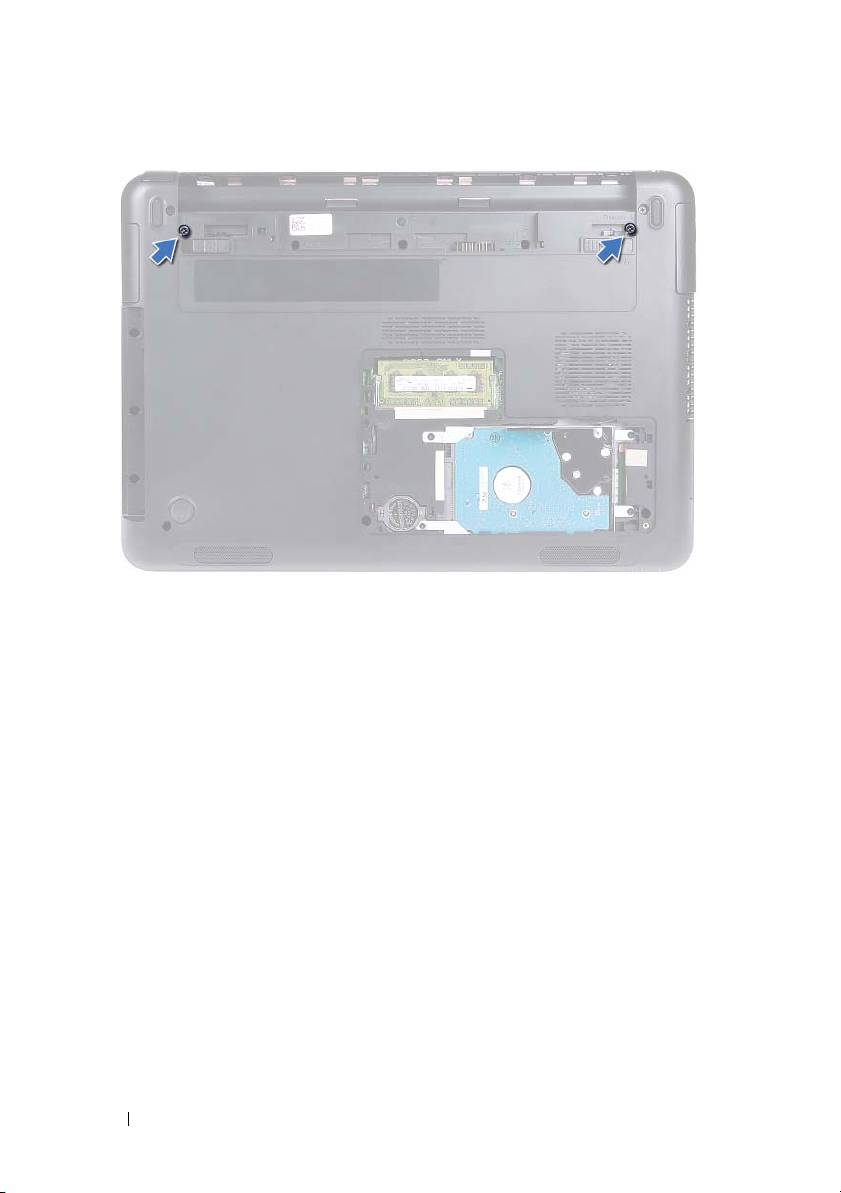
5
Remove the two screws that secure the display assembly to the computer
base.
Display 45
6
Turn the computer over.
7
Remove the keyboard. See "Removing the Keyboard" on page 31.
8
Remove the palm-rest assembly. See "Removing the Palm-Rest Assembly"
on page 35.
9
Turn the computer over and open the display as far as possible.
10
Disconnect the antenna cables from the mini-card. See "Removing the
Mini-Card" on page 41.
11
Lift the connector latch and disconnect the display cable from the
connector on the system board.
12
Disconnect the camera cable. See "Removing the Camera Module" on
page 65.
13
Note the routing of the display, camera, and mini-card antenna cables, and
remove the cables from their routing guides.
14
Remove the two screws that secure the display assembly to the computer
base.
46 Display
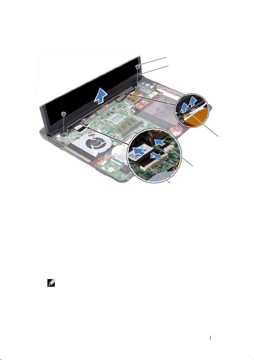
1 screws (2) 2 display assembly
3 mini-card antenna cables 4 camera-cable connector
5 display-cable connector
15
Lift the display assembly off the computer base.
Replacing the Display Assembly
1
Follow the instructions in "Before You Begin" on page 9.
2
Place the display assembly in position and replace the two screws that
secure the display assembly to the computer base.
NOTE: Ensure that no cables are caught between the display assembly and
the computer base.
3
Route the display, camera, and mini-card antenna cables through their
routing guides.
Display 47
1
2
3
4
5

4
Connect the camera cable. See "Replacing the Camera Module" on
page 67.
5
Slide the display cable in the connector on the system board and press
down the latch to secure the cable.
6
Connect the antenna cables to the mini-card. See "Replacing the
Mini-Card" on page 42.
7
Replace the palm-rest assembly. See "Replacing the Palm-Rest Assembly"
on page 38.
8
Replace the keyboard. See "Replacing the Keyboard" on page 33.
9
Turn the computer over.
10
Replace the two screws that secure the display assembly to the computer
base.
11
Follow the instructions from step 5 to step 6 in "Replacing the Optical
Drive" on page 25.
12
Replace the module cover. See "Replacing the Module Cover" on page 16.
13
Replace the battery. See "Replacing the Battery" on page 14.
CAUTION: Before turning on the computer, replace all screws and ensure that no
stray screws remain inside the computer. Failure to do so may result in damage to
the computer.
Hinge Cover
Removing the Hinge Cover
CAUTION: The hinge caps are extremely fragile. Be careful when removing the
hinge caps to prevent damaging them.
1
Follow the instructions in "Before You Begin" on page 9.
2
Remove the battery. See "Removing the Battery" on page 13.
3
Remove the module cover. See "Removing the Module Cover" on page 15.
4
Remove the optical-drive assembly. See "Removing the Optical Drive" on
page 23.
5
Remove the keyboard. See "Removing the Keyboard" on page 31.
48 Display

6
Remove the palm-rest assembly. See "Removing the Palm-Rest Assembly"
on page 35.
7
Remove the display assembly. See "Removing the Display Assembly" on
page 45.
8
Remove the two screws that secure the hinge cover to the computer base.
9
Pry out the six tabs that secure the hinge cover to the computer base and
remove the hinge cover from the computer base.
1 screws (2) 2 tabs (6)
Replacing the Hinge Cover
1
Follow the instructions in "Before You Begin" on page 9.
2
Align the tabs on the hinge cover to the slots on the computer base and
snap the hinge cover to the computer base.
3
Replace the two screws that secure the hinge cover in place.
Display 49
1
2

4
Replace the display assembly. See "Replacing the Display Assembly" on
page 47.
5
Replace the palm-rest assembly. See "Replacing the Palm-Rest Assembly"
on page 38.
6
Replace the keyboard. See "Replacing the Keyboard" on page 33.
7
Replace the optical-drive assembly. See "Replacing the Optical Drive" on
page 25.
8
Replace the module cover. See "Replacing the Module Cover" on page 16.
9
Replace the battery. See "Replacing the Battery" on page 14.
CAUTION: Before turning on the computer, replace all screws and ensure that no
stray screws remain inside the computer. Failure to do so may result in damage to
the computer.
Display Bezel
Removing the Display Bezel
1
Follow the instructions in "Before You Begin" on page 9.
2
Remove the display assembly. See "Removing the Display Assembly" on
page 45.
CAUTION: The display bezel is extremely fragile. Be careful when removing the
bezel to prevent damage.
3
Using your fingertips, carefully pry up the inside edges of the display bezel.
4
Lift the display bezel off the display assembly.
50 Display
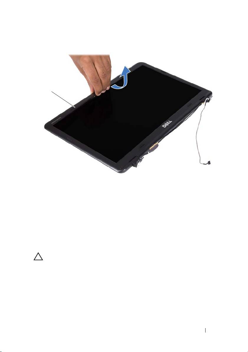
1 display bezel
Replacing the Display Bezel
1
Follow the instructions in "Before You Begin" on page 9.
2
Align the display bezel with the display cover and snap the display bezel
into place.
3
Replace the display assembly. See "Replacing the Display Assembly" on
page 47.
CAUTION: Before turning on the computer, replace all screws and ensure that no
stray screws remain inside the computer. Failure to do so may result in damage to
the computer.
Display Panel
Removing the Display Panel
1
Follow the instructions in "Before You Begin" on page 9.
Display 51
1
2
Remove the display assembly. See "Removing the Display Assembly" on
page 45.
3
Remove the display bezel. See "Removing the Display Bezel" on page 50.
4
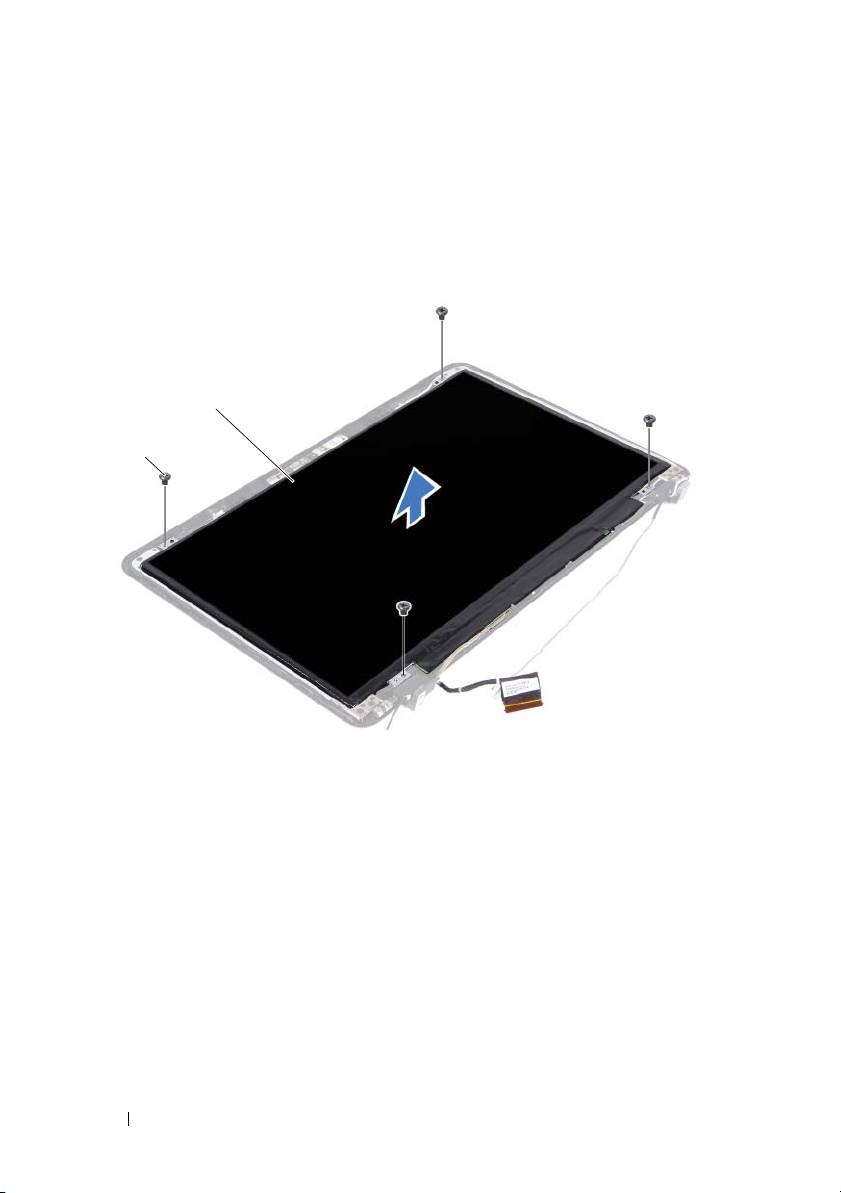
Remove the four screws that secure the display panel to the display cover.
1 screws (4) 2 display panel
5
Lift the display panel off the display cover.
6
Turn the display panel over and place the panel on a clean surface.
7
Lift the tape that secures the display cable to the display panel and
disconnect the display cable from the connector on the display panel.
52 Display
2
1
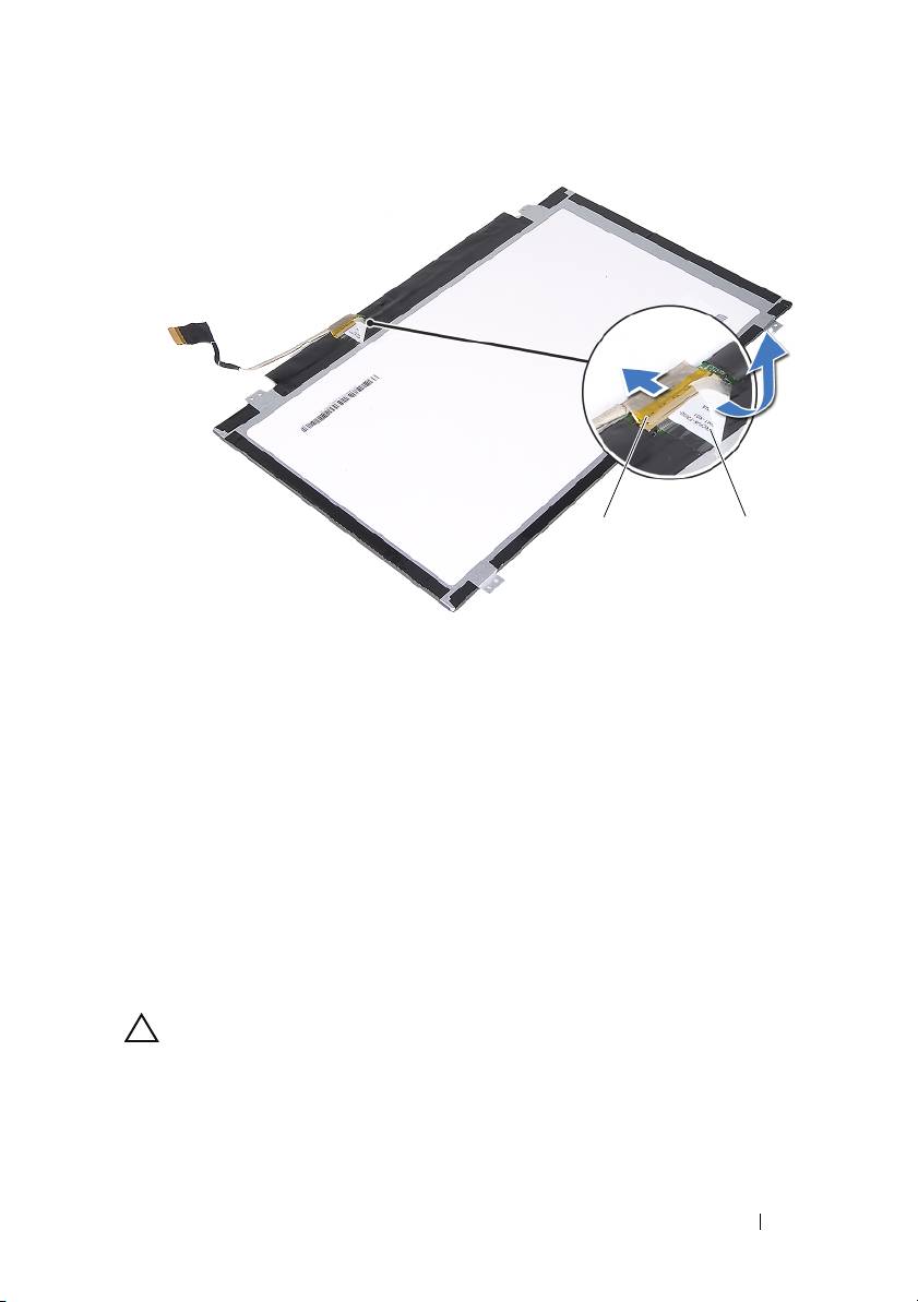
1 display-cable connector 2 tape
Replacing the Display Panel
1
Follow the instructions in "Before You Begin" on page 9.
2
Connect the display cable to the display-board connector and adhere the
display cable with the tape.
3
Align the display panel on the display cover.
4
Replace the four screws that secure the display panel to the display cover.
5
Replace the display bezel. See "Replacing the Display Bezel" on page 51.
6
Replace the display assembly. See "Replacing the Display Assembly" on
page 47.
CAUTION: Before turning on the computer, replace all screws and ensure that no
stray screws remain inside the computer. Failure to do so may result in damage to
the computer.
Display 53
12
Hinge Assembly
Removing the Hinge Assembly
1
Follow the instructions in "Before You Begin" on page 9.
2
Remove the display assembly. See "Removing the Display Assembly" on
page 45.
3
Remove the display bezel. See "Removing the Display Bezel" on page 50.
4
Follow the instructions from step 4 to step 5 in "Removing the Display
Panel" on page 51.
5
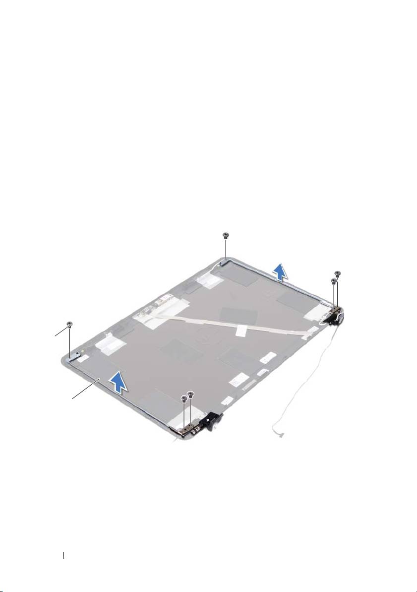
Remove the six screws that secure the hinge assembly to the display cover.
1 screws (6) 2 hinge assembly
6
Lift the hinge assembly away from the display cover.
Replacing the Hinge Assembly
1
Follow the instructions in "Before You Begin" on page 9.
54 Display
1
2

2
Place the hinge assembly on the display cover.
3
Replace the six screws that secure the hinge assembly to the display cover.
4
Follow the instructions from step 3 and step 4 in "Replacing the Display
Panel" on page 53.
5
Replace the display bezel. See "Replacing the Display Bezel" on page 51.
6
Replace the display assembly. See "Replacing the Display Assembly" on
page 47.
CAUTION: Before turning on the computer, replace all screws and ensure that no
stray screws remain inside the computer. Failure to do so may result in damage to
the computer.
Display 55

56 Display
Оглавление
- Contents
- Before You Begin
- Battery
- Module Cover
- Coin-Cell Battery
- Hard-Drive Assembly
- Optical Drive
- Memory Module(s)
- Keyboard
- Palm-Rest Assembly
- Wireless Mini-Card
- Display
- DC-in Connector Assembly
- USB Board
- Camera Module
- Thermal Fan
- System Board
- Heat-Sink Assembly
- Media-Card Reader Board
- Speakers
- System Setup
- Flashing the BIOS
