Hama EWS-170: g Operating Instruction
g Operating Instruction: Hama EWS-170
g Operating Instruction
Congratulations on your of purchasing this new In-Out Thermo Clock. This unique product is
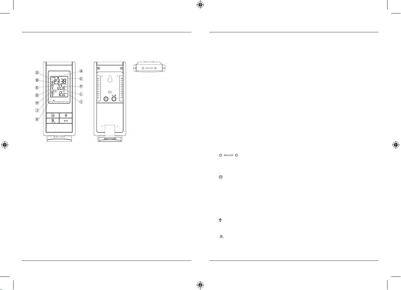
G. Indoor temperature alert
designed for everydayuse for the home or office and is a definite asset of great use. To fully
Set the upper or lower temperature limit for indoor temperature, the unit will beep
benefit from all the features and understand thecorrect operation of this product, please read
5 seconds every minute to alertthe user while the indoor temperature rises or falls beyond
this instruction manual thoroughly.
the pre-defined range.
H. Outdoor temperature indicator
Indicates the current outdoor remote sensor signal received. It can display up to 3 different
remote sensors
I. Outdoor maximum /minimum temperature indicator
Indicates the maximum/minimum outdoor temperature is displayed
J. Outdoor temperature alert
Set the upper or lower temperature limit for 3 remote thermo sensors. The unit will beep
5 seconds every minuteto alert the user while the remote thermo sensor’s temperature rises
or falls beyond the pre-defined range.
K. Auto scroll indicator
The animated rolling arrow icon is shown to indicate the auto scroll of 3 different remote
channels.
L. Remote sensor battery low indicator
Appears when the batteries of the remote sensor are running dry and the temperature mea-
sured by this sensor isno longer reliable. The user must change the batteries at once.
DESCRIPTION OF BUTTONS
FUNCTIONS OF THE IN-OUT THERMO CLOCK
The model has 7 major function buttons on top, front and back.
This In-Out thermo clock measures temperature of the environment of its surrounding
1. (
) [LIGHT-SNOOZE]
area and receives up to threeoutdoor thermometer for temperature.
Press once to turn backlight on for 5 seconds. Stop alarm sound temporary for 8 minutes
The data is continuously updated to bring you the latest weather informationdisplayed
when alarm sounds.
on the LCD of the receiving unit.
2. (
) [CLOCK]
FEATURES: MAIN UNIT
Toggle for clock, calendar or alarm display mode;
A. Clock window
Clock HR:MIN « Calendar Day-MON « Alarm HR:MIN
Displays DCF radio controlled clock, calendar or alarm time
(unit auto returns to clock display mode after viewing either calendar or alarm display for 10
B. Radio reception signal
seconds)
Indicates the condition of DCF77 radio controlled time reception.
Press 2s to activate setting mode for corresponding displayed mode – clock/calendar/
C. Alarm on icon
alarm
Appears when alarm is activated.
D. Low Battery Indicator
3. (
) [MEM]
Shown to indicate the battery in the main unit is low and all displayed information in LCD
Toggle for max or min temperature memory reading for both IN & OUT thermometers Press
is no longer reliable. Theuser needs to change the batteries at once.
and hold 2 seconds to clear both IN/OUT temperature memory.
E. Indoor temperature indicator
4. (
) [CH]
Indicates the indoor temperature is displayed.
Toggle to display remote thermo channel from channel 1, channel 2, channel 3 to Auto-scroll
F. Indoor maximum /minimum temperature indicator
mode which alternately display 3 channels;Press and hold 2 seconds to activate searching
Indicates the maximum/minimum indoor temperature is displayed.
mode for remote sensor;
10
11
00092654man_bg_de_en_fr_nl_pl_ro_ru.indd 10-11 12.01.12 16:02
5. ( ) [ALERT]
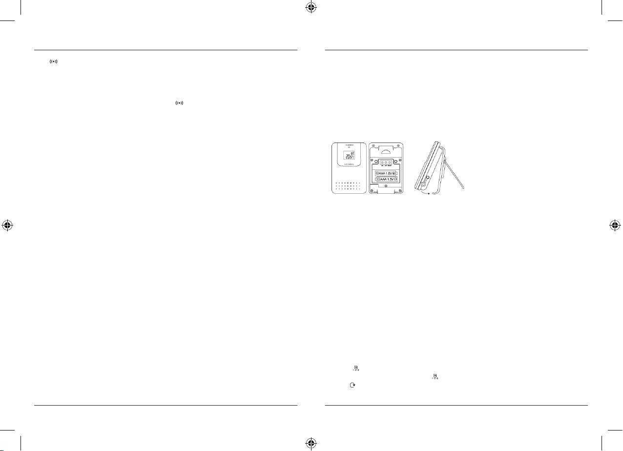
BATTERY INSTALLATION FOR REMOTE SENSOR UNIT
Toggle to display high temperature alert and then low temperature alert for indoor
1. Lift off the bracket stand of the remote sensor unit by releasing the 2 fixing snaps at the
thermometer, channel 1, 2, 3remote thermometers respectively and then return to normal
bottom;
thermo display mode;
Press & hold for 2 seconds at the desired alert temperature display to enter its setting mode,
2. Use a small type screwdriver to remove the battery cover screws;
use [+] / [-] keys to change the settings, press [
] again to confirm the setting or press on
key for 5 seconds to auto-exit to normal thermo display and confirm the setting;
3. Insert 2 pieces of AAA size batteries according to the “+” and “-” polarity marks shown in
the battery compartment and then close the battery door.
6. + [UP]
Increase the setting
Remote Sonsor
Press and hold 2 seconds to manually activate radio controlled function; press once again
deactivate radio controlled function;
7. - [DOWN]
Decrease the setting
Toggle Daily Alarm on/off when display shows Alarm mode;
Toggle Alert on/off when display shows corresponding Temperature Alert mode.
Bracket Stand
And 2 buttons inside battery compartment
Lift of this part
8. [°C/°F]
Toggle the temperature unit °C <- -> °F
WIRELESS REMOTE SENSOR REGISTRATION PROCEDURE
1. Insert 2 AAA batteries first to the main unit. The temperature display shows - - . – while
9. [Reset]
the wave icon will keep blinking for 2 minutes indicate the main unit is in sensor searching
To activate system reset to the main unit during abnormal condition which will reset all
mode.
settings back to factory values.
2. In a second step, insert the 2 AAA batteries into the sensor unit. The LED on the front panel
will start flashing at a rate of one time per around 2 seconds indicates channel-1 is in use.
GETTING STARTED
3. While the LED is flashing, press once the [CH] key will change the sensor channel setting
This In-Out thermo clock was designed for easy set up. For best operation, the following steps
to 2. Keep toggle on [CH] key can change channel setting up to 3. The LED is blinking at a
are required to be donein the proper sequence.
frequency to indicate the channel setting. i.e. continuous blinks 2 times indicate channel-2 is
1. Insert batteries for main unit before doing so for the sensor units.
selected.
2. Receiving unit cannot be programmed manually until the wireless remote sensor unit regis-
Note: If user does not press any key for 10 seconds, it will exit the channel setting mode
tration procedure has been completed.
and transmit the RF signal. The main unit will register the temperature reading.
3. Position the remote unit and main unit within effective transmission range, which, in usual
circumstances, is 50 m. Although the remote unit is weather resistant, it should be placed
REMOTE CHANNEL AUTO-SCROLLING
away from direct sunlight, rain or snow.
This device is equipped with an auto-scroll function. While the auto-scroll function is set, the
unit will automatically cycle to display the temperature of each remote sensor for 6 seconds.
BATTERY INSTALLATION FOR MAIN UNIT
1. Remove the battery door;
1. To retrieve manually the specific sensor temperature and humidity reading,
2. Insert 2 pieces AAA size 1.5V alkaline battery as indicate by the polarity;
press
key until desired channel number is displayed.
3. Close the battery door.
2. To enable auto-scroll function, use
button to toggle channel 1,2,... until auto scroll
Note: Replace the batteries when the low battery indicator appears on the
icon appears beside the channel indicator.
top-right corner of the LCD.
12
13
00092654man_bg_de_en_fr_nl_pl_ro_ru.indd 12-13 12.01.12 16:02
DCF 77 RADIO CONTROLLED CLOCK
6. D and M icons will flash. Press [ + ] or [ - ] to select D M (Date Month) or M D (Month Date)
The radio-controlled time is calculated by the Cesium Atomic clock of Braunschweig
format. Press [
] button to confirm.
(official clock of Germany). Then the time is coded and transmitted from Mainflingen – near
Frankfurt – via a signal on DCF-77 (77.5 kHz). The transmitting range of the signal is 1500 km,
7. Month digits will flash. Press [ + ] or [ - ] button to set your desired month. Press [ ] button
which means that most of Western and Central Europe is covered by this signal.
to confirm. Do the same to set Date.
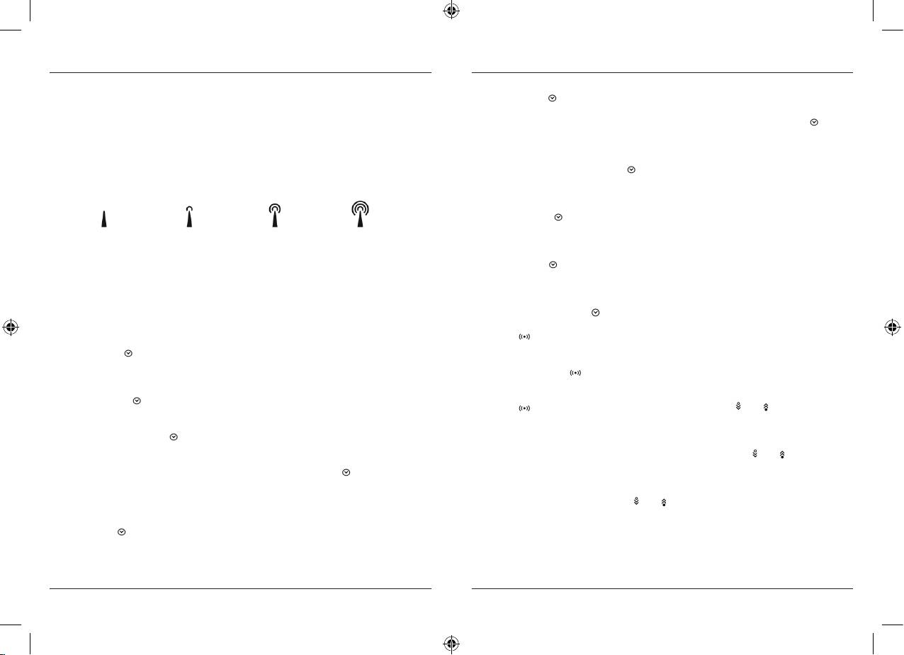
Within this range the received time is completely accurate. Once sensor signal(s) are
received, the wave icon will flash to indicate that the receiving unit starts to receive
TO SET DAILY ALARM
the DCF radio controlled time signal. Radio Controlled wave icon can indicate 4 levels
1. In clock time display mode, press [ ] button twice to display alarm time for 10 seconds.
of signal status:
2. Press [-] button in alarm display mode to arm or disarm the daily alarm.
3. Press and hold [ ] for 2 seconds to enter the alarm setting mode.
4. The hour digit will flash, use [ + ] button to increase by one hour or [ - ] button to decrease by
Very weak Weak Medium Strong
one hour to your desired hours. Hold down the button will change the increment
rapidly. Press [ ] button to confirm.
Once the time signal is received, the wave icon will stay on the LCD, and time and calendar will
automatically be updated.
5. The minute digits will flash. Use [ + ] button to increase by one minute or [ - ] button to
decrease by one minute to your desired minutes. Hold down the button will change the
Note: During the 10-minute time signal reception, all manual settings will be suspended.
increment rapidly. Press [ ] button to confirm and finish the setting.
If setting is desired, press once [ + ] key to deactivate the reception. You can also press
HOW TO SET TEMPERATURE ALERT
and hold the same key for 2 seconds to manually activate the reception in normal mode.
1. Press [ ] key to your desire Hi or Lo temperature limit for designated IN or REMOTE
SET THE CLOCK & CALENDAR
thermo at the desirable channel;
1. Press & hold [ ] button for 2 seconds to enter clock setting mode.
Flashing 24 hours will appear.
2. Press and hold the [ ] key for 2 seconds, the corresponding display digits start blinking;
3. Use the [ + ] & [ - ] keys to change for your desired setting;
2. Press [ + ] or [ - ] button to switch between 24 hours and 12 hours format,
and then press [ ] button to confirm.
4. Press [ ] key to confirm setting and exit the setting mode. (“ ” or “ ” icon appears to
3. The hour digits will flash. Use the [ + ] button to increase by one hour or [ - ] button to
indicate the lower or upper alert is armed)
decrease by one hour to your desired hours. Holding down either button will change the
increment rapidly. Press [ ] button to confirm.
5. Auto-exit the temperature alert display and returns to current temperature display mode
after 5 seconds. (Hi-Lo temperature limit icon disappears; leaving “ ” or “ ” icon to
4. The minute digits will flash. Use the [ + ] button or [ - ] button to set your desired minutes.
indicator alert is armed.)
Holding down either button will change the increment rapidly. Press [ ] button to
confirm.
6. To disarm the temperature alert – go to the desired temperature alert display mode, press [
Note: Every change of minute digit will automatically reset the seconds to zero.
- ] key once to disable the alert, the “ ” or “ ” icon disappears.
5. The year digit will flash and Yr icon appears. Press [ + ] or [ - ] button to set your desired
year. Press [ ] button to confirm.
Note: Year range is from 2000 to 2099.
14
15
00092654man_bg_de_en_fr_nl_pl_ro_ru.indd 14-15 12.01.12 16:02
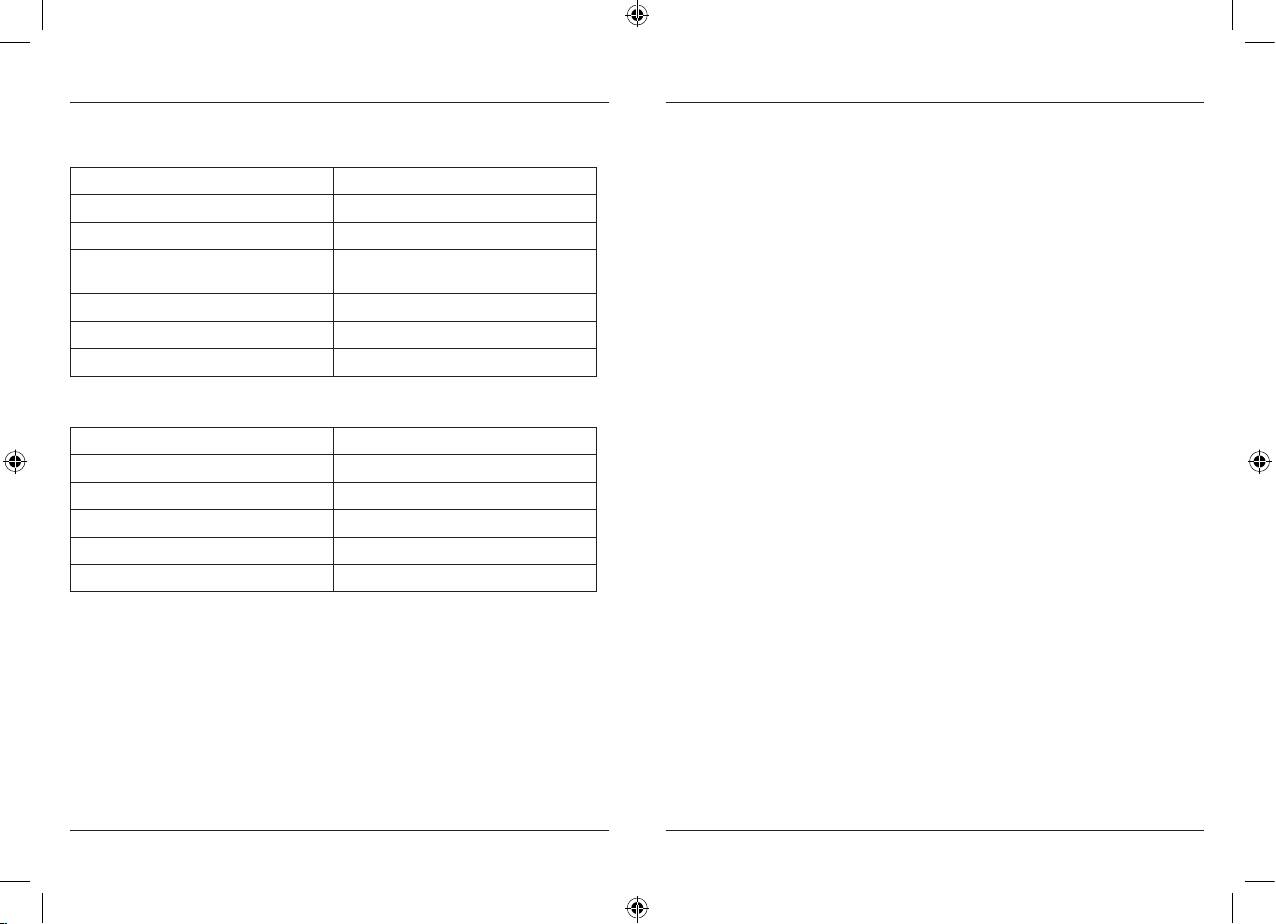
SPECIFICATIONS
Registration and Safety Certification/General Information
This device bears the CE symbol as specified by the provisions of Directive R & TTE (1999/5/EC).
Main Unit
Hama GmbH & Co. KG hereby declares that this device is in compliance with the basic
requirements and other relevant guidelines and regulations of the 1999/5/EC guideline.
Displayed IN temperature range: -10 °C to +60,0 °C (14 °F to 140,0 °F)
You will find the declaration of compliance and declaration of conformity in the Internet at
Proposed operating range: 0 °C to +50,0 °C (32,0 °F to 122,0 °F)
http://www.hama.com
Temperature resolution: 0,1 °C (0,2 °F)
Remote Temperature measurement
-50,0 °C to +70,0 °C (-58,0 °F to 158,0 °F)
Displayed OUT temperature range:
Temperature resolution: 0.1°C (0.2°F)
Battery: DC 3 V, 2 x AAA size
Snooze: 8 minutes
Remote Unit
Sensor with LCD Display: 0 °C to +50,0 °C (+32,0 °F to 122,0 °F)
Temperature resolution: 0,1 °C (0,2 °F)
RF Transmission Frequency: 433 MHz
Transmission Range: 30 meters/100 feet, open area
Temperature sensing cycle: 60 - 75 seconds
Battery: DC 3V, 2 x AAA size
The information in this document has been viewed and is believed to be accurate. However,
neither the manufacturer nor its affiliates assume any responsibility for inaccuracies, errors
or omissions that may be contained herein. In no event will the manufacturer or its affiliates
be liable for direct, indirect, special, incidental or consequential damages arisen by using this
product or resulting from any defect/omission in this document, even if advised of the possibility
of such damages.
The manufacturer and its affiliates reserve the right to make improvements or changes to this
document and the products and services described at any time, without notice or obligation.
16
17
00092654man_bg_de_en_fr_nl_pl_ro_ru.indd 16-17 12.01.12 16:02
