Hama VMPL: инструкция
Раздел: Аксессуары для телевизоров
Тип:
Инструкция к Hama VMPL
ENGLISH
ESPAÑOL DEUTSCH FRANÇAIS ITALIANO PYCCKO
Spanish German French Italian Russian Japanese Mandarin
International Assembly Instructions for model VMPL
中文
Sanus Systems 2221 Hwy 36 West, Saint Paul, MN 55113 7.05.05
Customer Service: (800) 359-5520 • (651) 484-7988 • fax (651) 636-0367
Customer Service Europe: 31 (0)20 5708938 • fax 31 (0)20 5708989
See complementary Sanus products at www.sanus.com

ENGLISH
Assembly Instructions for VMPL Flat Panel Wall Mount
Thank you for choosing a Sanus Systems Vision Mount Wall Mount. This product is designed to mount flat panel televisions weighing
up to 175 lb. to a vertical wall. It allows you to tilt your new television up to 15º without the use of tools.
Safety Warning: If you do not understand these directions, or have any doubts about the safety of the installation, please call a qualified
contractor or contact Sanus at 800.359.5520 (US) or 31 (0)20 5708938 (Europe). You can also visit our web site at www.sanus.com. We
can quickly assist you with installation questions and missing or damaged parts. Replacement parts for Sanus products purchased through
authorized dealers will be shipped directly to you. Check carefully to make sure there are no missing or defective parts. Never use defective
parts. Improper installation may cause damage or serious injury. Do not use this product for any purpose that is not explicitly specified by
Sanus Systems. Sanus Systems can not be liable for damage or injury caused by incorrect mounting, incorrect assembly, or incorrect use.
Note: The supplied wall mounting hardware is not for steel stud walls or old cinder block walls. If you are uncertain about the nature of
your wall, consult an installation contractor. Sanus makes every effort to assure all necessary television mounting hardware is included.
If the hardware you need is not included please consult your local hardware store or call Sanus Systems.
Required Tools: 3/16 drill bit, 1/2” Masonry Bit for brick concrete or concrete block installations, wrench or socket, Phillips screw driver.
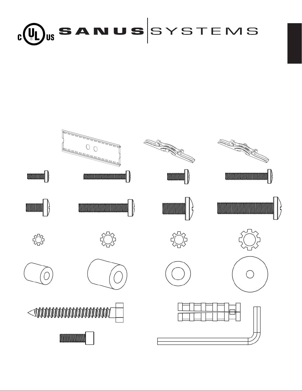
Supplied Parts:
(1) Wall Plate - a (1) Left Monitor Bracket - b (1) Right Monitor Bracket - c
(4) M4 x 12 Bolt - d (4) M4 x 30 Bolt - e (4) M5 x 12 Bolt - f (4) M5 x 30 Bolt - g
(4) M6 x 12 Bolt - h (4) M6 x 35 Bolt - i (4) M8 x 16 Bolt - j (4) M8 x 40 Bolt - k
(4) M4 Lock Washer - l (4) M5 Lock Washer - m (4) M6 Lock Washer - n (4) M8 Lock Washer - o
(4) M4/M5 Spacer - p (4) M6/M8 Spacer - q (6) Lag Bolt Washer - r (8) M4/M5 Washer - s
(6) Lag Bolt - t (6) Conrete Anchor - u
(2) Safety Bolt - v (1) Allen Key - w
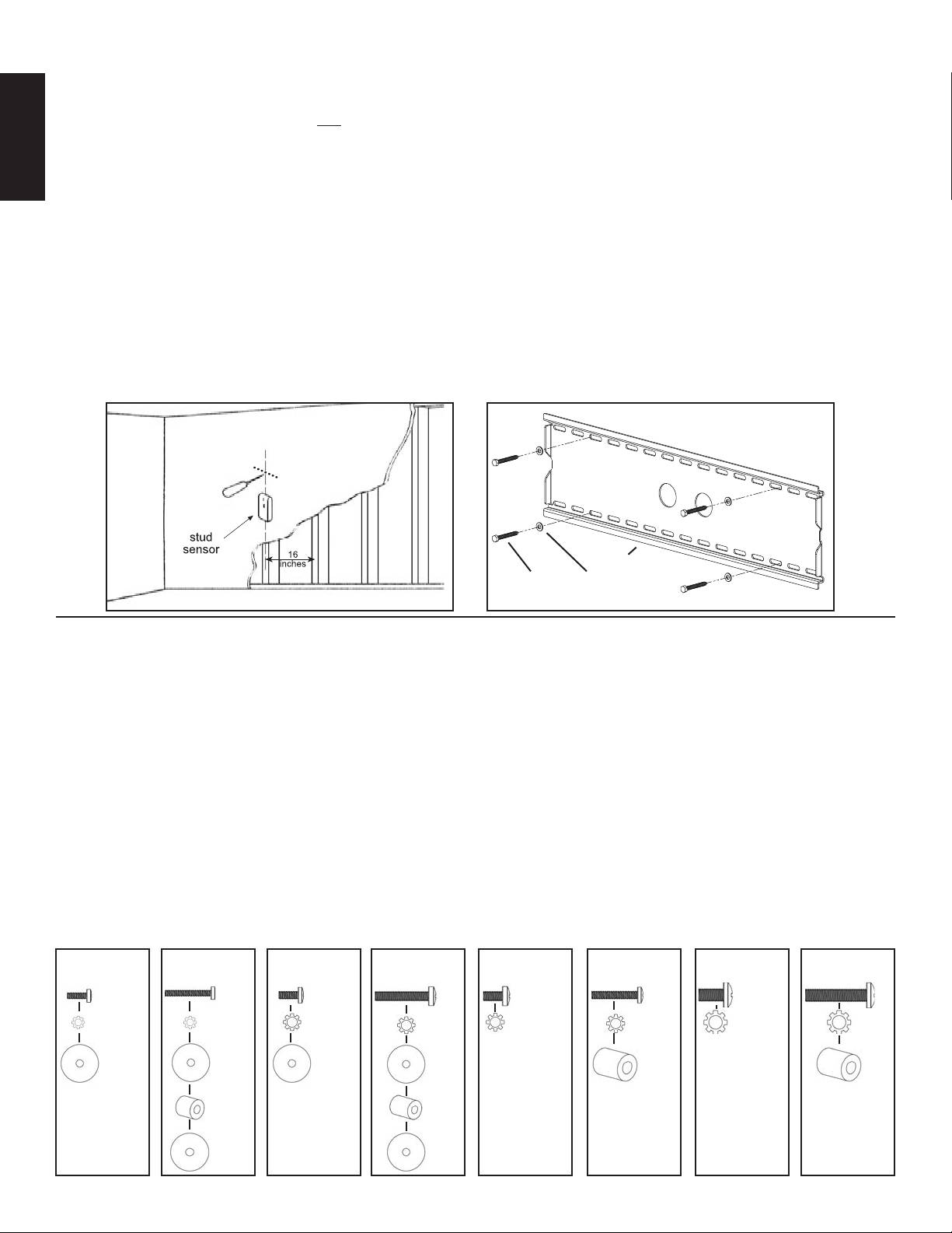
Step 1: Mounting the Wall Plate: Wood Stud, Brick, Solid Concrete, and Concrete Block mounting options are provided.
Wood Stud mounting:
The Wall Plate (a) must be mounted to two wood studs at least 12" apart. Use a high quality stud sensor to locate two adjacent
studs. It is a good idea to verify where the studs are located with an awl or thin nail shown in Diagram 1a. Pre-drill a 2.5" deep hole at
the desired height in each stud using a 3/16" drill bit. Make sure these holes are in the center area of the studs and level with each other.
Use the Wall Plate as a template to mark the location of the second hole in each stud. Drill 2.5" deep holes using the 3/16" drill bit in the
ENGLISH
marked location. Attach the Wall Plate to the wall using the four 1/4 x 2.5” Lag Bolts (t) and four Lag Bolt Washers (r). Make sure the
Wall Plate is oriented so the flat surface in the center of the plate is against the wall and that a set of Lag Bolts is on each side of the two
large holes in the center as shown in Diagram 1b.
Brick, Solid Concrete and Concrete Block mounting:
Use the Wall Plate (a) as a template to mark 6 hole locations on the wall. The outer holes must fall to left and right of the two large holes
in the middle of the plate. Three in the top row of slots and three more in the bottom row. Make sure these holes are level and there is at
least 6" between any two holes. Pre-Drill these holes with a 1/2" masonry bit to at least 2.5" in depth. Insert a Concrete Anchor (u) into
each of these holes. Make sure the anchor is seated completely flush with the concrete surface even if there is a layer of drywall or other
material in front. Attach the Wall Plate to the wall using 6 Lag Bolts (t) and 6 Lag Bolt Washers (r).
Diagram 1a Diagram 1b
a
t r
Step 2: Select the Appropriate Hardware for your television
Always make sure the television is unplugged before threading any bolt into the back panel!
Thread bolts carefully into your television by hand before tightening. If you feel resistance, remove the bolt immediately! If you
are unable to find appropriate hardware for your television, consult a local hardware store or call Sanus Systems.
Locate the threaded inserts on the back of your flat panel television and determine which of the provided Bolts is the correct diameter.
To test each diameter, thread the Bolts carefully into your television by hand until you find the diameter that correctly fits.
Next, determine the correct length of the required Bolt. Televisions with a flat back will require one of the shorter Bolts without a spacer.
Some televisions have a curved back or have recessed threaded inserts. This may require a longer Bolt along with a Spacer placed be-
tween the television and the Monitor Bracket.
Once you have the correct bolt picked out, you can follow the diagrams below to see what additional hardware you will need to mount
the Monitor Brackets (b,c) to your television. For a television with a flat back, see Step 3 for installation instructions. For a television
with a curved back see Step 4. For a television that has a back with recessed threaded inserts see Step 5.
Hardware Diagrams:
M4 x 12
M4 x 30
M5 x 12
M5 x 30
M6 x 12
M6 x 35
M8 x 16
M8 x 40
d e f g h i j k
l l m m n n o o
s s s s q q
p p
s s
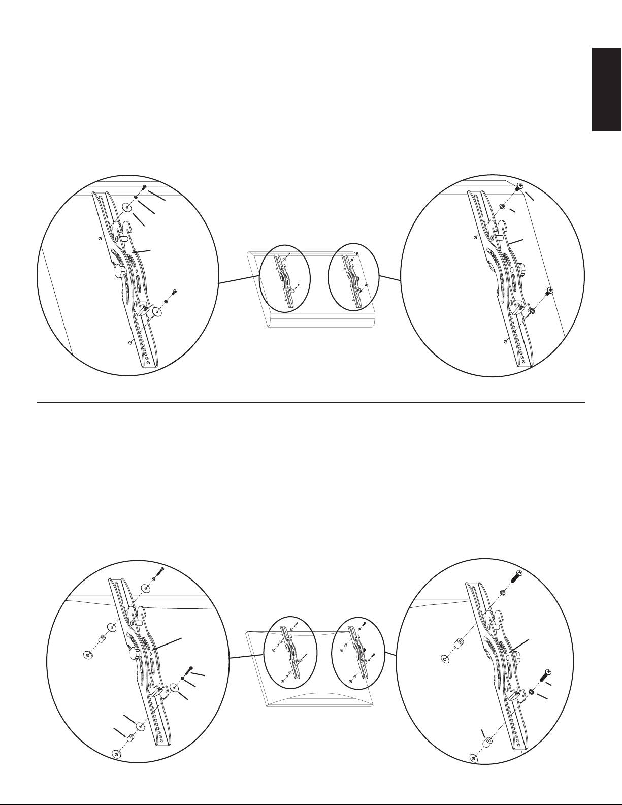
Step 3: Attaching the Monitor Brackets to a TV with a flat back
ENGLISH
WARNING: DO NOT LAY THE TELEVISION FACE DOWN ON THE GLASS, lean it up against a wall or other solid surface!
Laying the television down on the glass may cause permanent damage.
The Monitor Brackets (b,c) should be placed as vertically close to center of the television as possible before installation. For a flat back
TV that requires the M4 or M5 diameter Bolt, thread a M4 x 12 (d) or a M5 x 12 (f) Bolt through the appropriate Lock Washer (l,m), an
M4/M5 Washer (s), the Monitor Bracket and finally into the TV. See Detailed View A of Diagram 3 for assistance. If your TV requires
the M6 or M8 diameter Bolt thread a M6 x 12 (h) or a M8 x 16 (j) Bolt through the appropriate Lock Washer (n,o), through the Moni-
tor Bracket and into the TV. See Detailed View B of Diagram 3 for assistance. Proceed to tighten the Bolts firmly with a phillips screw
driver.
Detailed View A Detailed View B
d,f h,j
l,m n,o
s Diagram 3
c
b
Step 4: Attaching the Monitor Brackets to a television with a curved back
WARNING: DO NOT LAY THE TELEVISION FACE DOWN ON THE GLASS, lean it up against a wall or other solid surface!
Laying the television down on the glass may cause permanent damage.
The Monitor Brackets (b,c) should be placed as vertically close to center of the television as possible before installation. If your TV has
a curved back and requires either a M4 or M5 diameter bolt, thread a M4 x 30 (e) or a M5 x 30 (g) Bolt through the appropriate Lock
Washer (l,m), an M4/M5 Washer (s), the Monitor Bracket, an M4/M5 Washer, a M4/M5 Spacer (p) and into the TV as seen in Detailed
View A of Diagram 4. If you determined that your TV requires a Bolt with a M6 or M8 Diameter, thread a M6 x 35 (i) or a M8 x 40 (k)
Bolt through the appropriate Lock Washer (n,o), the Monitor Bracket, a M6/M8 Spacer (q) and into the TV as seen in Detailed View B
of Diagram 4. Proceed to tighten the Bolts firmly with a phillips screw driver.
Detailed View A Detailed View B
Diagram 4
b c
e,g
l,m i,k
s n,o
s
p q
Step 5: Attaching the Monitor Brackets to a television with recessed threaded inserts.
WARNING: DO NOT LAY THE TELEVISION FACE DOWN ON THE GLASS, lean it up against a wall or other solid surface!
Laying the television down on the glass may cause permanent damage.
The Monitor Brackets (b,c) should be placed as vertically close to center of the television as possible before installation. If your TV has
threaded inserts that are recessed and requires either a M4 or M5 diameter bolt, thread a M4 x 30 (e) or a M5 x 30 (g) Bolt through the
ENGLISH
appropriate Lock Washer (l,m), an M4/M5 Washer (s), the Monitor Bracket, an M4/M5 Washer, a M4/M5 Spacer (p) and into the TV as
seen in Detailed View A of Diagram 5. If you determined that your TV requires a Bolt with a M6 or M8 Diameter, thread a M6 x 35 (i)
or a M8 x 40 (k) Bolt through the appropriate Lock Washer (n,o), the Monitor Bracket, a M6/M8 Spacer (q) and into the TV as seen in
Detailed View B of Diagram 5. Proceed to tighten the Bolts firmly with a phillips screw driver.
Detailed View A Detailed View B
Diagram 5
b c
e,g i,k
l,m n,o
s
s q
p
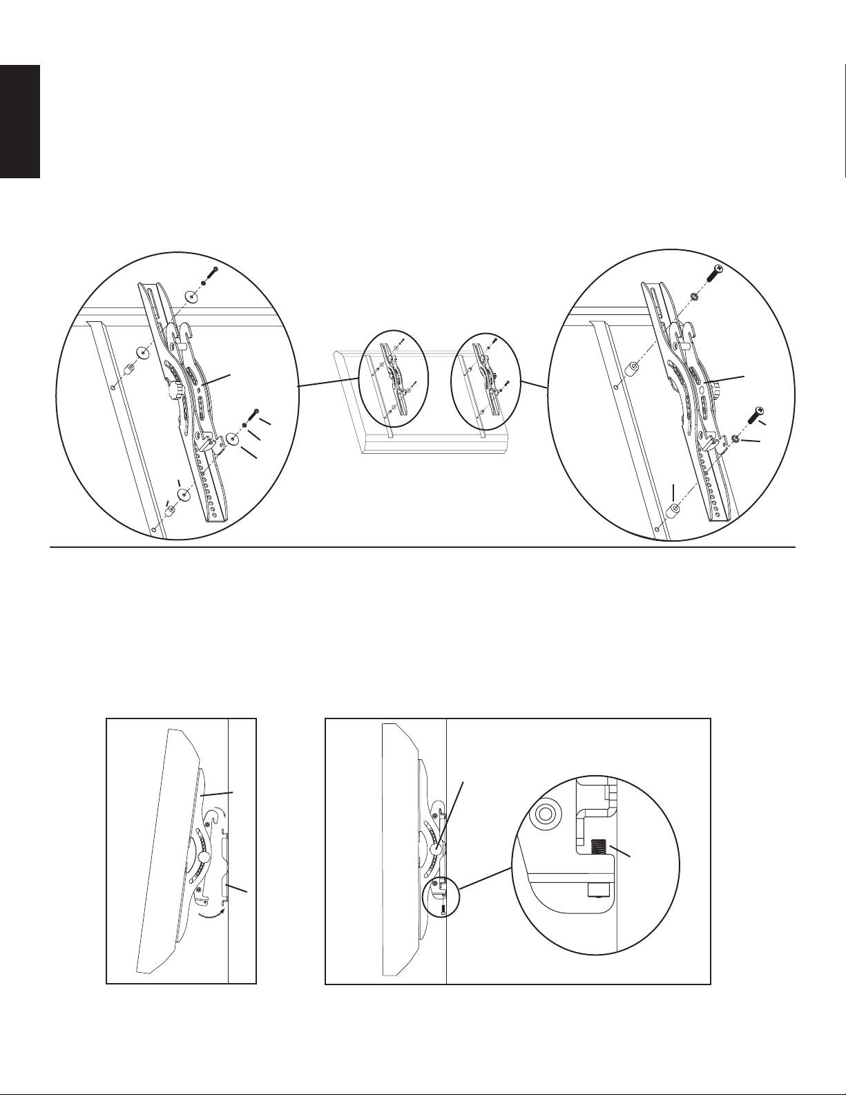
Step 6: Attaching Monitor to Wall Plate and adding Safety Bolts
Warning: Some televisions may require 2 people to lift! Sanus is not responsible for personal injury or product damage.
First hook the Monitor Brackets (b,c) over the top of the Wall Plate (a), then let the bottom of the Monitor Brackets rotate in under the
bottom of the Wall Plate as shown in diagram 6a. Insert the Safety Bolts (v) into the threaded holes in the bottom of the Monitor Brackets.
Tighten them with the Allen Key (w) so that they sit behind the bottom tab on the Wall Plate as shown in the Detailed View of Diagram
6b. Finally loosen the knobs and you are free to adjust your new flat panel TV.
Diagram 6a Diagram 6b
Detailed View
Knob
b,c
v
a
Оглавление
- ENGLISH ESPAÑOL DEUTSCH FRANÇAIS ITALIANO PYCCKO Spanish German French Italian Russian Japanese Mandarin
- ENGLISH
- ESPAÑOL
- DEUTSCH
- FRANÇAIS
- ITALIANO
- PYCCKO
- M4 x 12 M4 x 30 M5 x 12 M5 x 30 M6 x 12 M6 x 35 M8 x 16 M8 x 40
- 中文
- M4 x 12 M4 x 30 M5 x 12 M5 x 30 M6 x 12 M6 x 35 M8 x 16 M8 x 40
- 中文
