Hama VM200: инструкция
Раздел: Аксессуары для телевизоров
Тип:
Инструкция к Hama VM200
ENGLISH
ESPAÑOL DEUTSCH FRANÇAIS ITALIANO PYCCKO
Spanish German French Italian Russian Japanese Mandarin
International Assembly Instructions for model VM200
中文
Sanus Systems 2221 Hwy 36 West, Saint Paul, MN 55113 7.05.05
Customer Service: (800) 359-5520 • (651) 484-7988 • fax (651) 636-0367
Customer Service Europe: 31 (0)20 5708938 • fax 31 (0)20 5708989
See complementary Sanus products at www.sanus.com

ENGLISH
Assembly Instructions for Model: VM200
Thank you for choosing a Sanus Systems VisionMount™ wall mount. The VM200 is designed to mount up to 40” LCD TVs weighing less than 80 lbs
to a vertical wall. It will allow you to effortlessly tilt the TV ±20°.
Safety Warning: If you do not understand these directions, or have any doubts about the safety of the installation, please call a qualied contractor
or contact Sanus at 800.359.5520 or www.sanus.com. Check carefully to make sure that there are no missing or defective parts. Our customer service
representatives can quickly assist you with installation questions and missing or damaged parts. Replacement parts for products purchased through
authorized dealers will be shipped directly to you. Never use defective parts. Improper installation may cause damage or serious injury. Do not use this
product for any purpose that is not explicitly specied by Sanus Systems. Sanus Systems can not be liable for damage or injury caused by incorrect
mounting, incorrect assembly, or incorrect use. Please call Sanus Systems before returning products to the point of purchase.
Note: The supplied wall mounting hardware is not for metal stud or old cinder block walls. If you are uncertain about the nature of your wall, consult
an installation contractor. Sanus makes every effort to assure all necessary television mounting hardware is included. If the hardware you need is not
included please consult your local hardware store or call Sanus Systems.
Required Tools: Drill, 3/16” drill bit, (1/2” masonry bit for brick, concrete, or concrete block installations), socket set and a Phillips screw driver
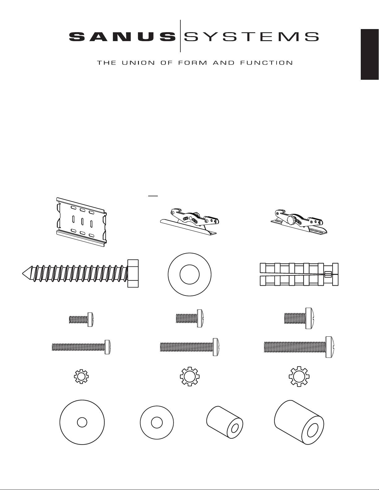
Supplied Parts and Hardware: Some parts not shown as actual size*
(1) Left Monitor Bracket - b* (1) Right Monitor Bracket - c*
(1) Wall Plate - a*
(3) Lag Bolt - d (3) Concrete Anchor - f
(3) Lag Bolt Washer - e
TV Mounting Hardware:
(4) M4 x 10 mm Bolt - g (4) M5 x 12 mm Bolt - h (4) M6 x 12 mm Bolt - i
(4) M4 x 30 mm Bolt - j (4) M5 x 30 mm Bolt - k (4) M6 x 35 mm Bolt - l
(4) M4 Lock Washer - m (4) M5 Lock Washer - n (4) M6 Lock Washer - o
(4) M4/M5 Washer - p (4) M6 Washer - q (4) M4/M5 Spacer - r (4) M6 Spacer - s
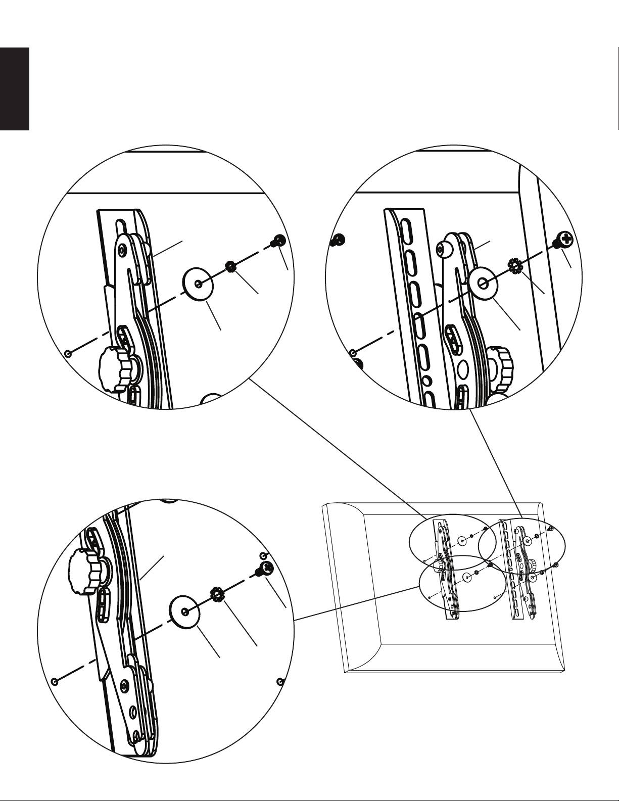
Step 1: Mount Monitor Brackets to a television with a at back
First, determine the diameter of the Bolt (g,h,i) your TV requires by hand threading them into the threaded insert on the back of the TV. If
you encounter any resistance stop immediately! Once you have determined the correct diameter, see the appropriate Diagram below. You
will thread the Bolt through the appropriate Lock Washer (m,n,o), the corresponding Washer (p,q), the Monitor Bracket (b,c), and nally
into the TV. Make sure the Monitor Brackets are vertically centered and level with each other. See the appropriate Diagram below.
ENGLISH
Note: For televisions with a curved back, or an obstruction near the threaded insert see Step 2.
M4 Diameter Bolt M6 Diameter Bolt
c b
g i
m o
p q
M5 Diameter Bolt Diagram 1
c
h
n
p
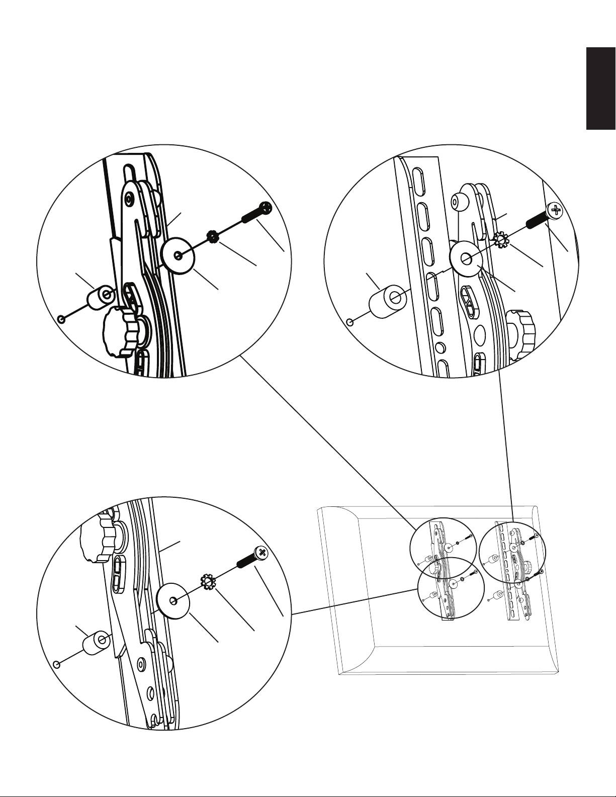
Step 2: Mount Monitor Brackets to a television with a curved back or an obstruction near the threaded insert
ENGLISH
First, determine the diameter of the Bolt (j,k,l) your TV requires by hand threading them into the threaded insert on the back of the TV.
If you encounter any resistance stop immediately! Once you have determined the correct diameter, see the appropriate Diagram below.
You will thread the Bolt through the appropriate Lock Washer (m,n,o), the corresponding Washer (p,q), the Monitor Bracket (b,c), a
Spacer (r,s), and nally into the TV. Make sure the Monitor Brackets are vertically centered and level with each other. See the appropriate
Diagram below.
M4 Diameter Bolt M6 Diameter Bolt
c b
j l
r m s o
p q
M5 Diameter Bolt Diagram 2
c
r k
n
p
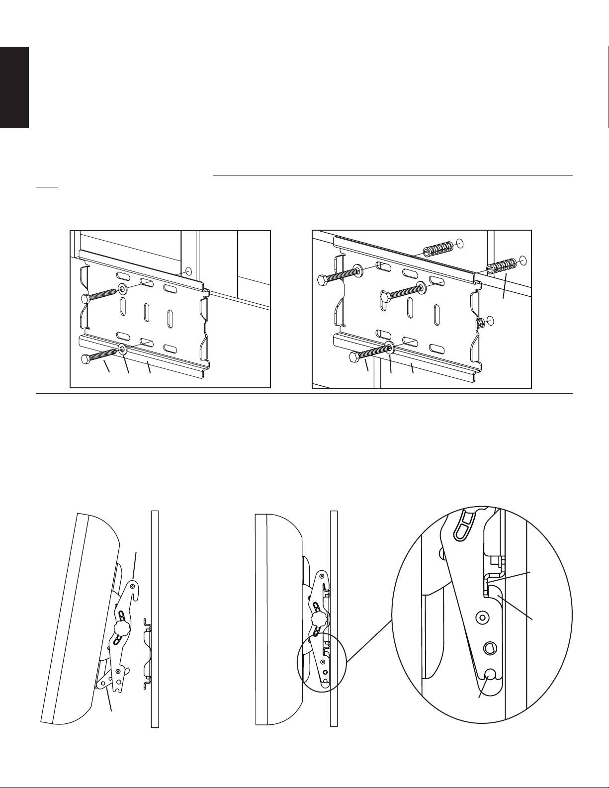
Step 3: Mounting the Wall Plate - wood stud, brick, solid concrete and concrete block mounting options are provided
Wood Stud Installation:
The Wall Plate (a) must be installed into a single wood stud. Use the Wall Plate as a template mark a location on the wall, one in the top
row of slots and the other in the corresponding slot in the bottom row. Pre drill a 2.5” deep hole into the wood stud by using a 3/16” drill
bit. Make sure wall the Wall Plate is oriented to the at surface is against the wall. Attach the Wall Plate to the wall using two Lag Bolts
(d) and two Lag Bolt Washers (e). See Diagram 3a for assistance.
ENGLISH
Brick, solid concrete and concrete block installation:
Use the Wall Plate (a) as a template to mark 3 locations on the wall. Two in the top row of slots and one more centered in the bottom row.
Carefully pre-drill a 2.5” deep hole with a 1/2” masonry drill bit. Never drill into the mortar between blocks! Insert a Concrete
Anchor (f) into each pre-drilled hole so it is ush with the concrete/brick surface even if there is a layer of drywall or other material in
front. Attach the Wall Plate to the wall using three Lag Bolts (d) and three Lag Bolt Washers (e). See Diagram 3b for assistance.
Warning: Do not overtighten the Lag Bolts! Tighten Lag Bolts only until the Lag Bolt Washer is pulled rmly against
the Wall Plate.
Diagram 3a Diagram 3b
f
d e a d e a
Step 4: Attach Monitor to Wall Plate
Rotate the latch handle into its most open position and hang the hooks of the Left and Right Monitor Brackets (b,c) over the tab on the
top of the Wall Plate (a) as shown in Diagram 4a. Once the Monitor Brackets are attached to the Wall Plate, rotate the latch handles on
each Monitor Bracket until they click into place. The tip of the latch handle should now be tucked up behind the tab on the bottom of the
Wall Plate as shown in the Detailed View of Diagram 4b. You may place a pad lock through the hole in the bottom of the latch handle if
you wish to add security to the installation.
Diagram 4a Diagram 4b Detailed View
b,c
bottom
tab
tip of
latch
handle
hole for
latch padlock
handle
Оглавление
- International Assembly Instructions for model VM200
- Assembly Instructions for Model: VM200
- Instrucciones de armado del modelo: VM200
- Montageanweisungen für das Modell: VM200
- Instructions d’assemblage pour le modèle : VM200
- Istruzioni di montaggio per il modello: VM200
- Инструкция по сборке крепления модели VM200
- VM200 モデルの組み立て説明書
- VM200 型号装配说明
