Hama MF110: инструкция
Раздел: Аксессуары для телевизоров
Тип:
Инструкция к Hama MF110
ENGLISH
ESPAÑOL DEUTSCH FRANÇAIS ITALIANO PYCCKO
Spanish German French Italian Russian Japanese Mandarin
International Assembly Instructions for model MF110
中文
Sanus Systems 2221 Hwy 36 West, Saint Paul, MN 55113 5.10.06
Customer Service: (800) 359-5520 • (651) 484-7988 • fax (651) 636-0367
Customer Service Europe: 31 (0)20 5708938 • fax 31 (0)20 5708989
See complementary Sanus products at www.sanus.com

ENGLISH
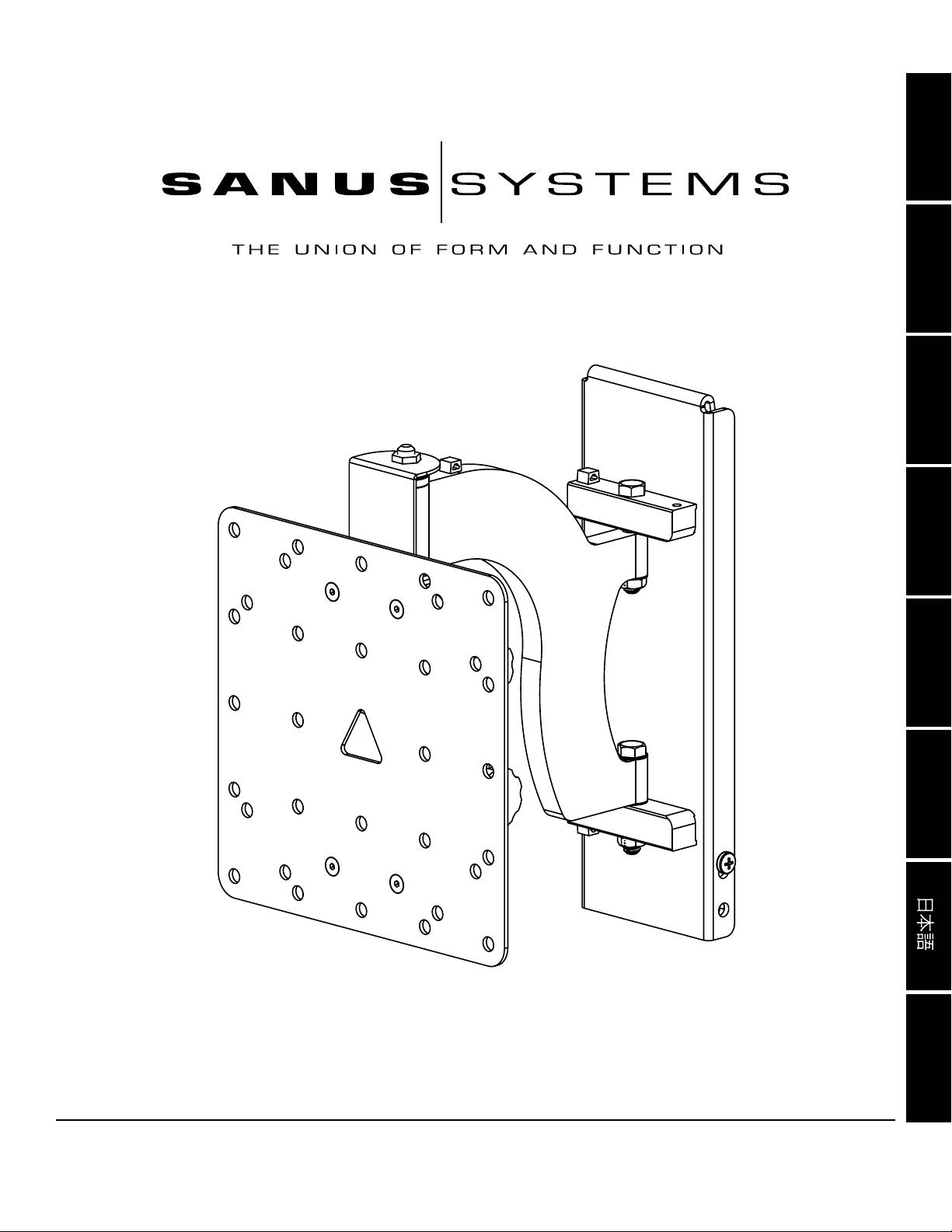
Assembly Instructions for Model: MF110
Thank you for choosing a Sanus Systems VisionMount™ wall mount. The MF110 is designed to mount LCD at panels with VESA
(Video Electronics Standards Association) hole pattern up to 200mm x 200mm and weighing up to 100 lb [45.5 Kg] to a vertical wall. It will
allow the television to be pulled out 9.5” [241.3 mm] from of the wall. It will allow you to swivel the television ±30° (may vary with size of
television), tilt +5° to -15°, and have a ±6° roll control.
WARNING: If you do not understand these directions, or have any doubts about the safety of the installation, please call a qualied
contractor or contact Sanus at 800.359.5520 or www.sanus.com. Check carefully to make sure that there are no missing or defective
parts. Our customer service representatives can quickly assist you with installation questions and missing or damaged parts. Replacement
parts for products purchased through authorized dealers will be shipped directly to you. Never use defective parts. Improper installation
may cause damage or serious injury. Do not use this product for any purpose that is not explicitly specied by Sanus Systems. Sanus
Systems can not be liable for damage or injury caused by incorrect mounting, incorrect assembly, or incorrect use. Please call Sanus
Systems before returning products to the point of purchase.
Required Tools: Drill, 3/16” drill bit, wrench set, philips screw driver
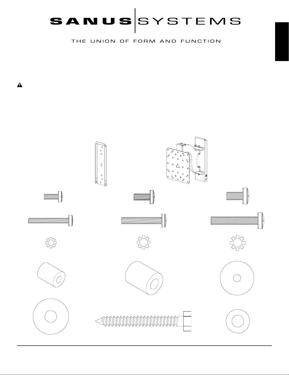
Supplied Parts and Hardware: Some parts not shown as actual size*
(1) Arm Assembly - B*
(1) Wall Plate - A*
(4) M4 x 12 mm Bolt - C
(4) M5 x 12 mm Bolt - D
(4) M6 x 12 mm Bolt - E
(4) M4 x 30 mm Bolt - F
(4) M5 x 30 mm Bolt - G
(4) M6 x 35 mm Bolt - H
(4) M4 Lock Washer - I
(4) M5 Lock Washer - J (4) M6 Lock Washer - K
(4) M4/M5 Spacer - L
(4) M6 Spacer - M
(4) M4/M5 Washer - N
(3) Lag Bolt - P
(4) M6 Washer - O
(3) Lag Bolt Washer- Q
Sanus Systems 2221 Hwy 36 West, Saint Paul, MN 55113 05.10.06 (100044)
Customer Service: 800.359.5520. See complementary Sanus products at www.sanus.com
ENGLISH
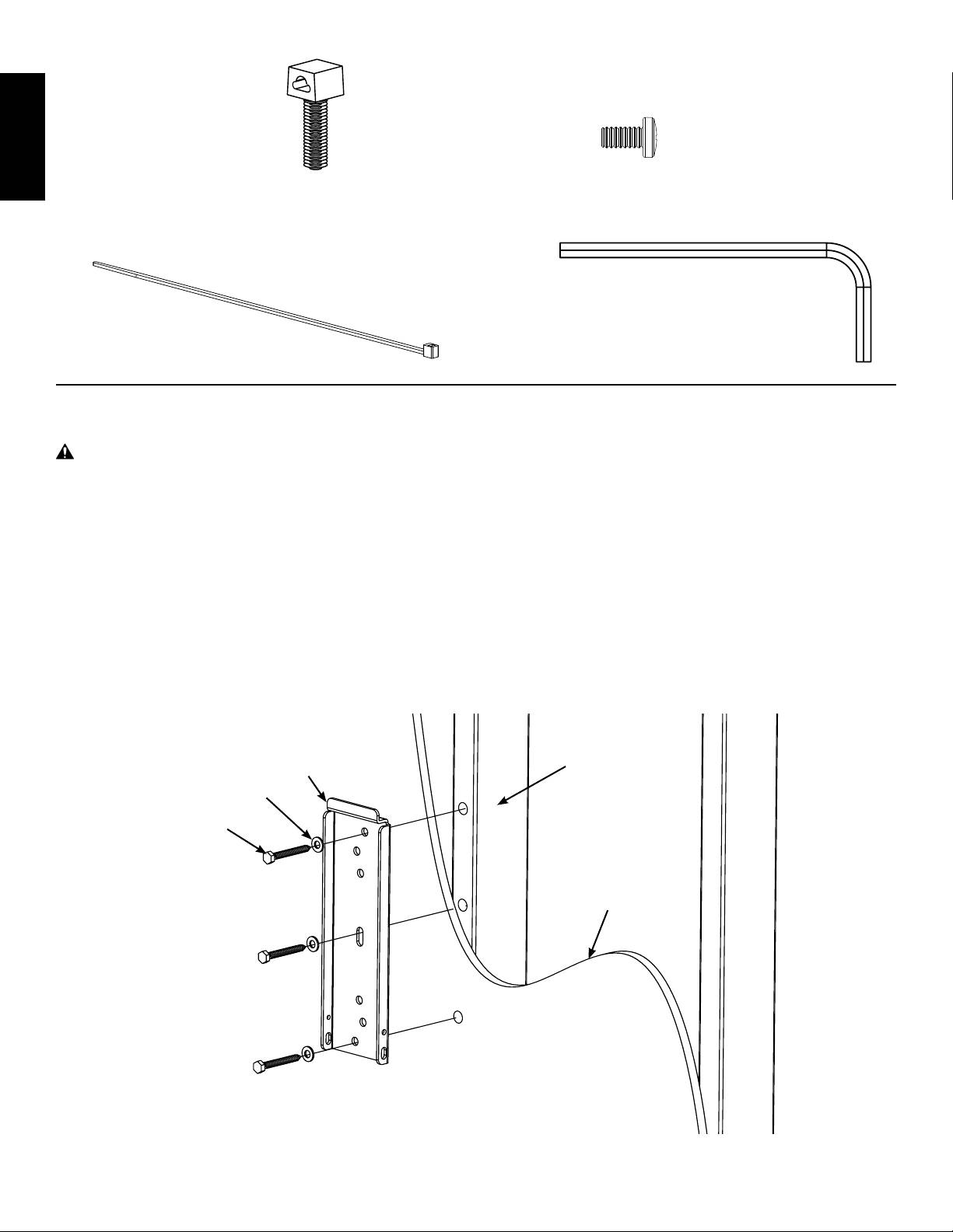
(3) Wire Tie Clip - R
(2) Safety Bolt - S
(3) Wire Tie - T
(1) Allen Key - U
Step 1: Mount the Wall Plate: Wood Stud installation only
WARNING: Do not overtighten the Lag Bolts. Overtightening the Lag Bolts may damage or weaken them.
Tighten lag Bolts only until Lag Bolt Washer is pulled rmly against the Wall Plate
Wood Stud Mounting: The Wall Plate (A) must be mounted to a wood stud. Use a high quality stud sensor to locate a stud.
It is a good idea to verify where the stud is located with an awl or thin nail. Pre-drill a 2.5” [63.5 mm] deep hole at the desired
height in the stud using a 3/16” drill bit. Make sure the hole is in the center area of the stud. Use this location for the middle
hole in the Wall Plate. Use the Wall Plate as a template to mark the location of the top and bottom holes. Make sure the Wall
Plate is level and drill a 2.5” [63.5 mm] deep hole using the 3/16” drill bit in the marked locations. Attach the Wall Plate to
the wall using three Lag Bolts (P) and three Lag Bolt Washers (Q). Make sure the Wall Plate is oriented so the at surface
in the center of the plate is against the wall. See Diagram 1 below.
NOTE: The TV will be vertically centered on the Wall Plate once it is mounted.
Diagram 1
Stud
A
Q
P
Drywall cutaway
to show studs.
Step 2: Add Arm Assembly to a television with a at back
ENGLISH
NOTE: If your television has a curved back, or any other obstruction, proceed directly to Step 3.
First, determine the diameter of the Bolt (C,D,E) your TV requires by hand threading them into the threaded insert on the
back of the TV. If you encounter any resistance stop immediately! Once you have determined the correct diameter, see the
appropriate Diagram below. You will thread the Bolt through the appropriate Lock Washer (I,J,K), a Washer (N, O), the Moni-
tor Plate, and nally thread it into the TV. Proceed to tighten all 4 Bolts until tight with a phillips screw driver.
NOTE: Arm has been cutaway in this Step to show critical parts.
M5 Diameter Bolt
N
M6 Diameter Bolt
J
D
O
K
E
M4 Diameter Bolt
N
I
C
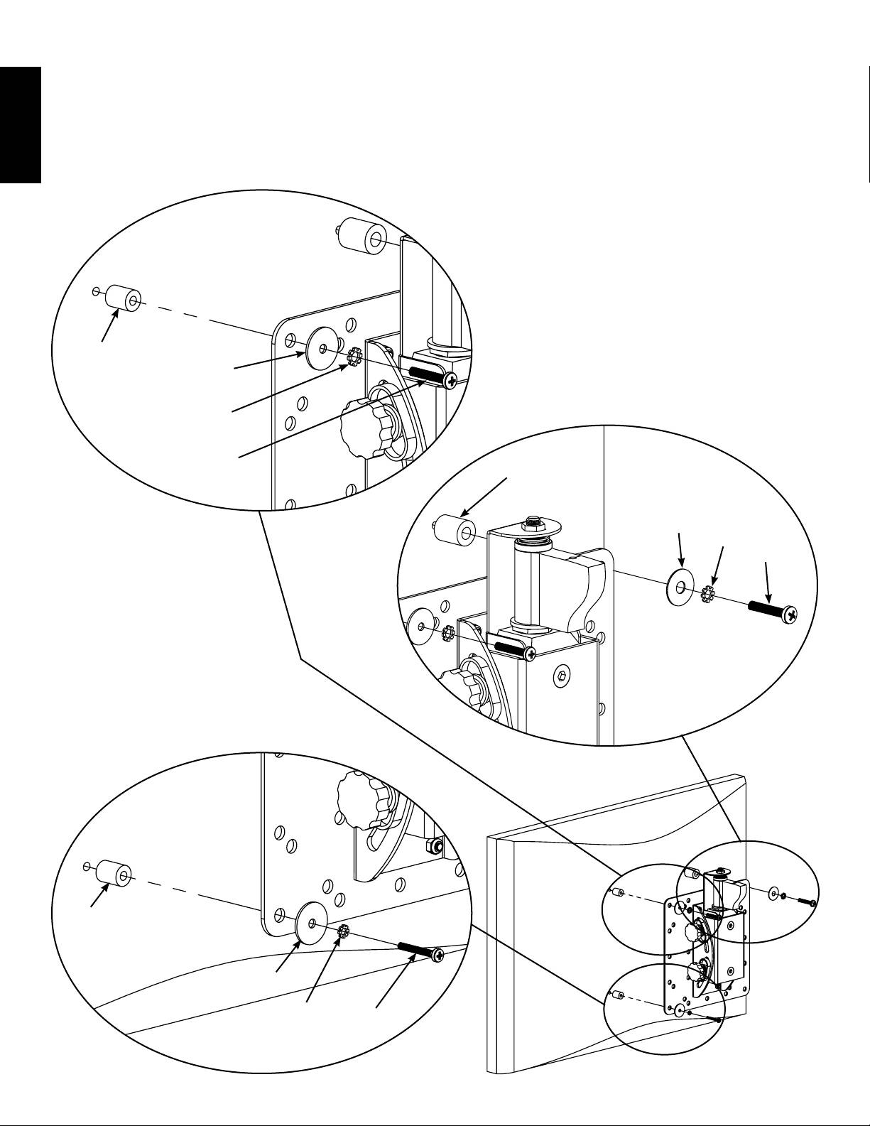
Step 3: Add Arm Assembly to a television with a curved back, recessed area around the threaded inserts or any
other obstruction.
First, determine the diameter of the Bolt (F,G,H) your TV requires by hand threading them into the threaded insert on the
back of the TV. If you encounter any resistance stop immediately! Once you have determined the correct diameter, see
the appropriate Diagram below. You will thread the Bolt through the appropriate Lock Washer (I,J,K), a Washer (N, O), the
Monitor Plate, the appropriate Spacer (L,M) and nally thread it into the TV.
ENGLISH
M5 Diameter Bolt
L
N
J
M6 Diameter Bolt
G
M
O
K
H
M4 Diameter Bolt
L
N
I
F
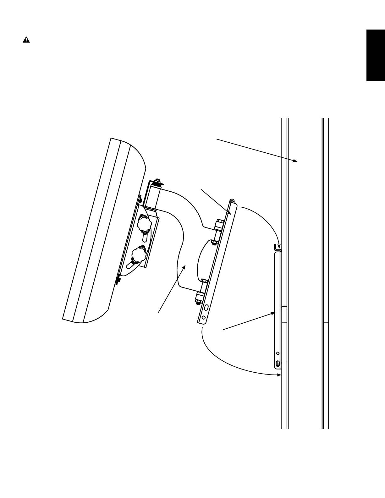
Step 4: Hang Arm Assembly on Wall Plate
ENGLISH
WARNING: This step may require 2 people to lift the assembly onto the Wall Plate! Sanus Systems is not respon-
sible for injury or damage.
Orient the Arm Assembly (B) so that the arm extends directly away from the television and the transfer bracket is parallel
with the television. Some televisions will require 2 people to lift! Lift up the assembly and hook the transfer bracket onto
the tab on the top of the Wall Plate (A) as shown in Diagram 4.
Diagram 4
Wall
Transfer Bracket
B
A
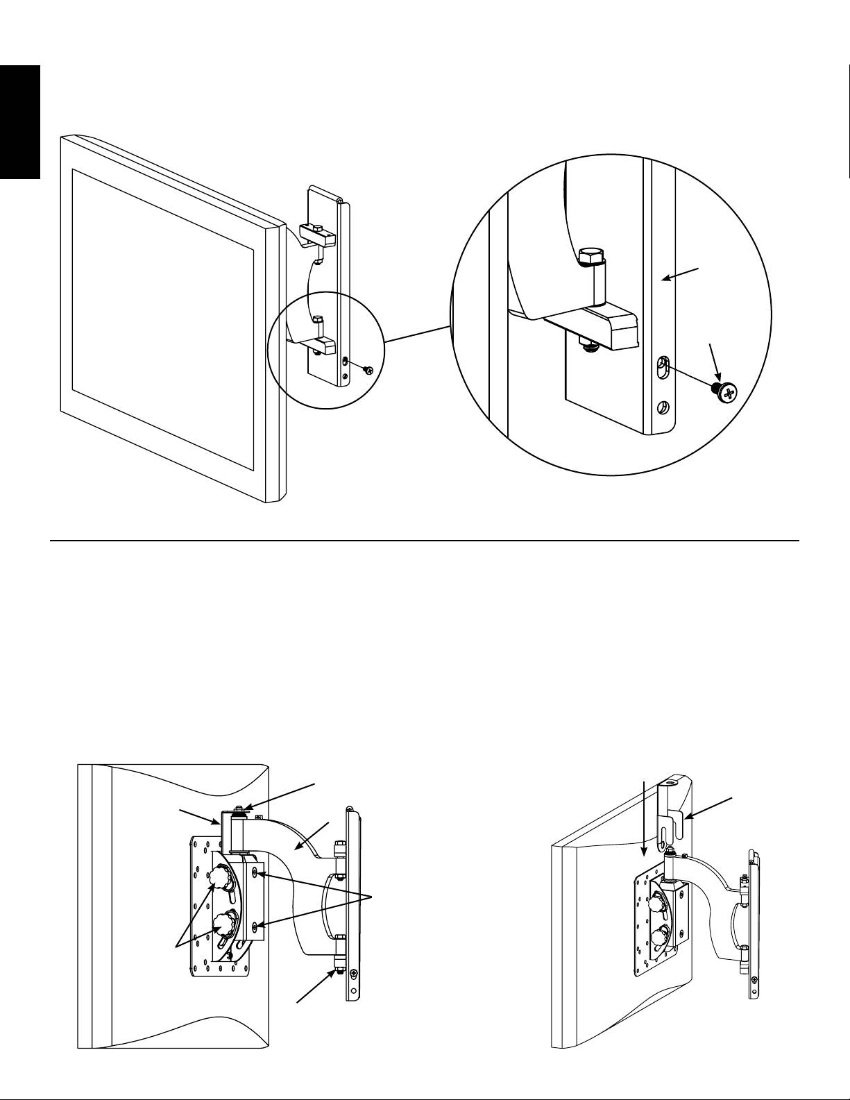
Step 5: Add Safety Bolts
Thread a Safety bolt (S) into the threaded hole on each side of the Transfer Bracket and tighten them with a phillips screw-
driver until they are tight. See the detailed View of Diagram 5 for assistance.
Detailed View
Diagram 5
ENGLISH
Transfer
Bracket
S
NOTE: Lower Hole on transfer bracket may be used to add a padlock for added security.
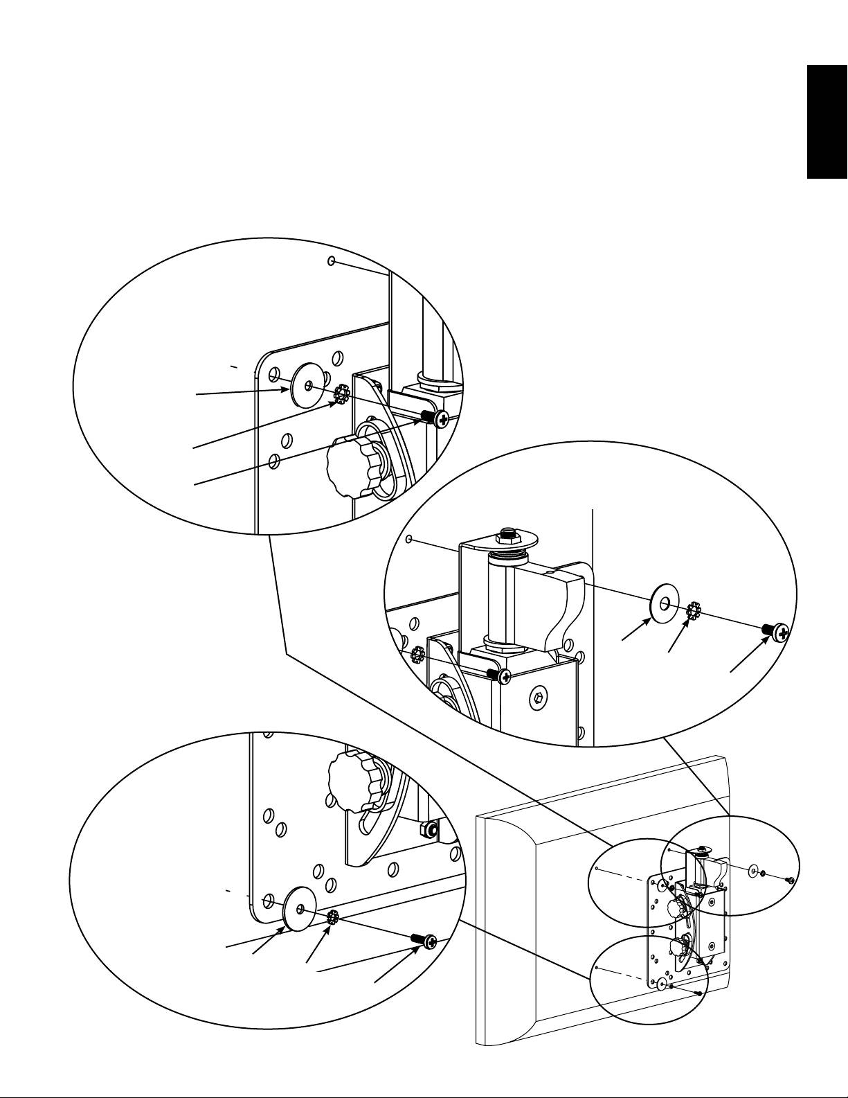
Step 6: Leveling and Adjusting Tension on the Monitor
CAUTION: Do not remove the Tension Nuts labeled in Diagram 6a.
Once the television is mounted onto the Wall Plate (A), and the Safety Bolts (S) are tight, it can be adjusted to level. Slightly
loosen the two Allen Bolts on the back of the Arm Assembly (B). Once those two bolts are loosened, the television can be
adjusted ±6º until level. When the television is level retighten the two Allen Bolts. The tilt can be adjusted by simply tilting
the television. If you need to adjust the tension of the tilt, you can do so with the Tension Knobs. The Tension Nuts labeled
in Diagram 6a can be slightly loosened or tightened to adjust the tension of the Arm Assembly. If you need to adjust the
Tension Nut closest to the TV, you must remove the Safety Bracket, adjust the tension and re-install the Safety Bracket as
shown in the Safety Bracket installation view of Diagram 6b.
Diagram 6a
Diagram 6b
Tension
Nut
Safety
Safety
Bracket
Bracket
B
Allen
Bolts
Tension
Knobs
Tension
Nut
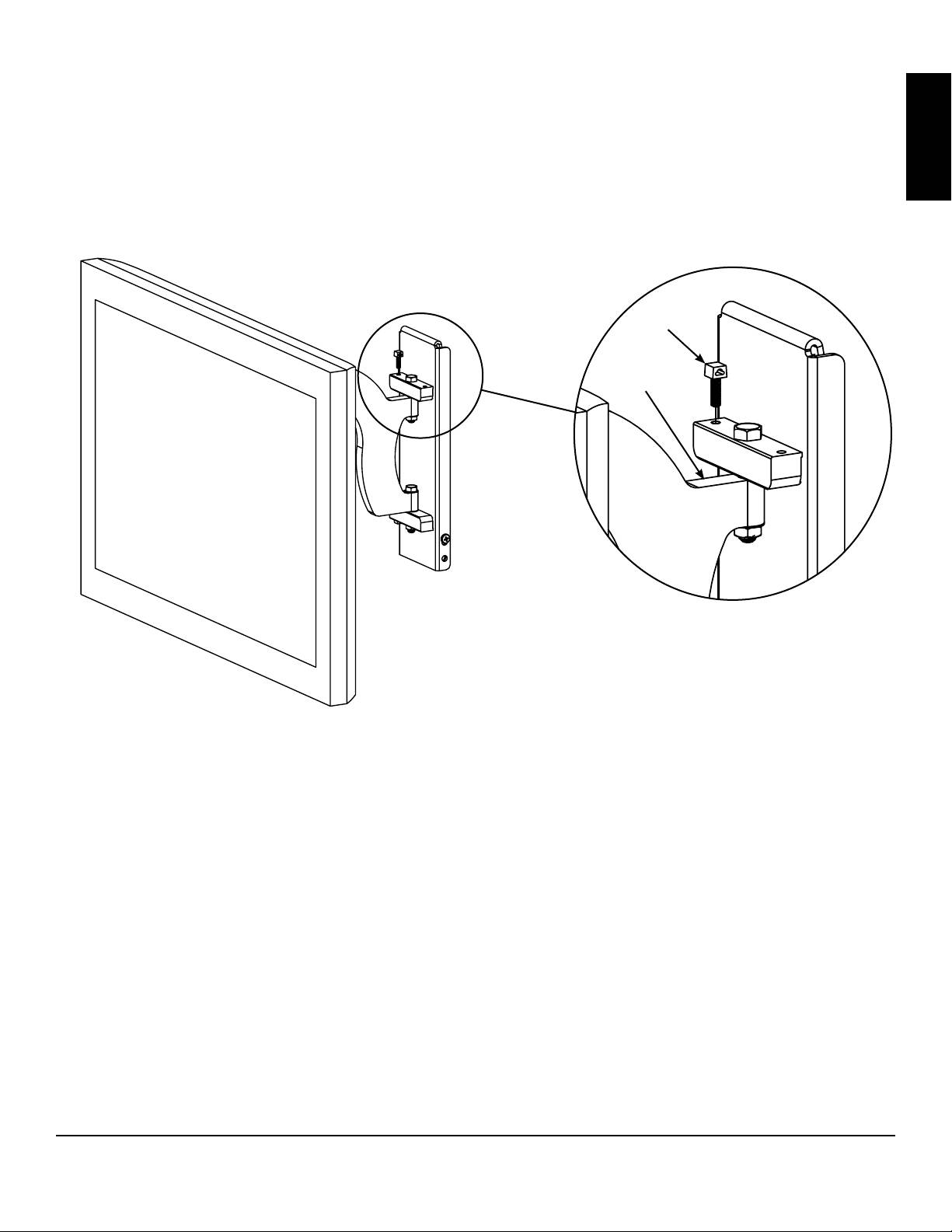
Step 7: Cable/Wire Management
ENGLISH
CAUTION: Do not run cables through a pinch point.
Before beginning cable management pull the television into the position as far from the wall as possible. Leave some slack
in the cables so that during motion so there is no added tension on the connectors. Wire Tie Clips (R) can be attached to the
holes in the top and the bottom of the Arm Assembly (B) by simply pressing them into place as shown in the Detailed View
of Diagram 7. Wire Ties (T) can then be added to the Wire Tie Clips.
Diagram 7 Detailed View
R
B
Sanus Systems 2221 Hwy 36 West, Saint Paul, MN 55113 05.10.06 (100044)
Customer Service: 800.359.5520. See complementary Sanus products at www.sanus.com
Оглавление
- International Assembly Instructions for model MF110
- Assembly Instructions for Model: MF110
- Instrucciones de ensamblaje del modelo: MF110
- Montageanleitung für Modell: MF110
- Instructions de montage pour le modèle : MF110
- Istruzioni di montaggio per il modello MF110
- Инструкция по сборке крепления модели MF110
- MF110 モデルの組み立て説明書: MF110
- MF110 型号装配说明
