Hama SFV49b: инструкция
Раздел: Аксессуары для телевизоров
Тип:
Инструкция к Hama SFV49b
ENGLISH
ESPAÑOL DEUTSCH FRANÇAIS ITALIANO Русский
Spanish German French Italian Russian Japanese Mandarin
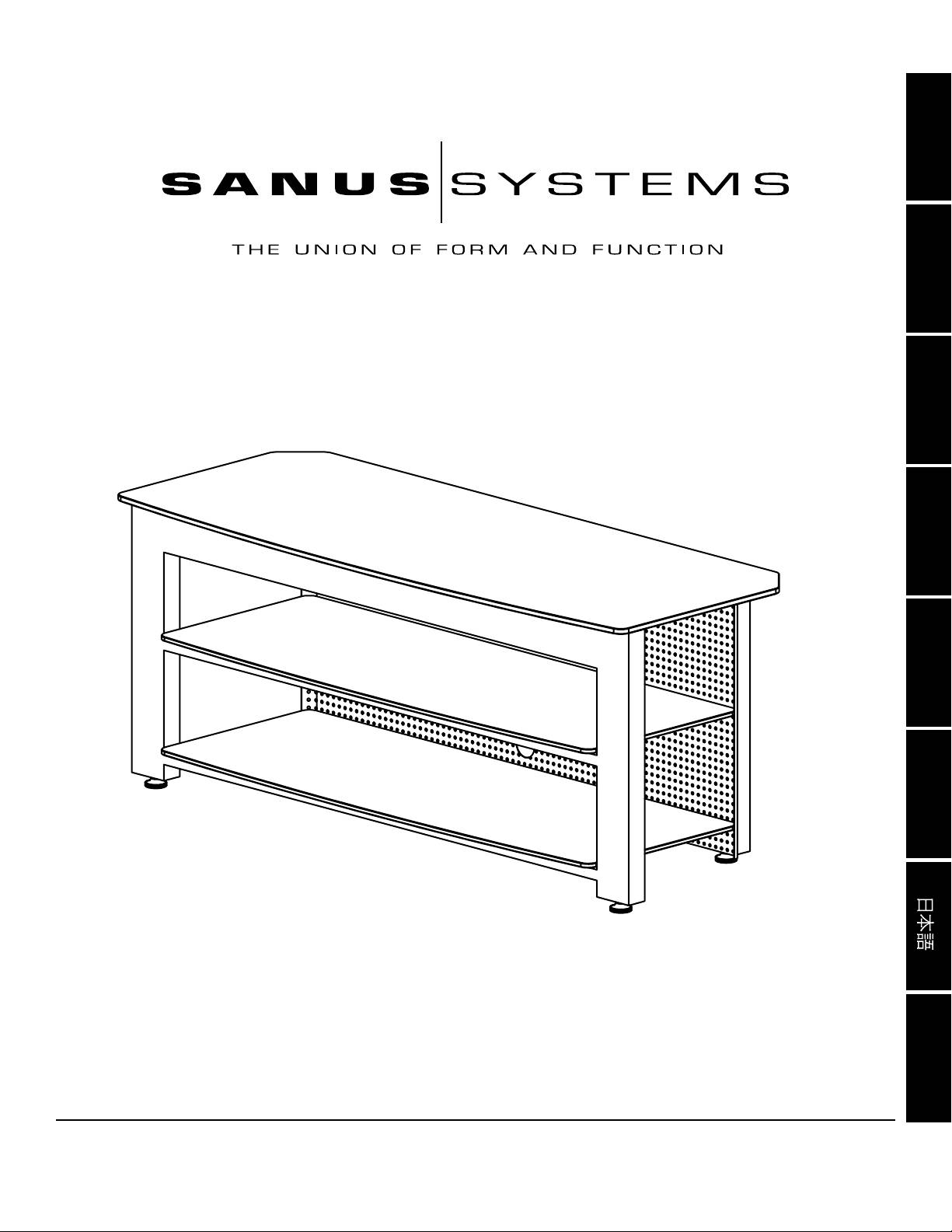
International Assembly Instructions for model SFV49
中文
Sanus Systems 2221 Hwy 36 West, Saint Paul, MN 55113 USA 8.06.04
Customer Service: (800) 359-5520 • (651) 484-7988 • fax (651) 636-0367
Customer Service Europe: +31 - (0)40 26 68 619 • fax +31 - (0)40 26 68 615
See complementary Sanus products at www.sanus.com

ENGLISH
Assembly Instructions for SFV49
Thank you for choosing the Steel Furniture line from Sanus Systems. If you have any questions regarding this or any other Sanus
Systems product, please contact us at 800.359.5520 or visit us at www.sanus.com. Our customer service representatives can assist you
quickly with any issues regarding assembly or missing parts. Check carefully to make sure none of the parts are missing or defective.
Never use defective parts. Replacement parts for products purchased from an authorized dealer will be shipped directly to you. Please
call Sanus Systems before returning products to retail stores.
Required Tools: Phillips screw driver
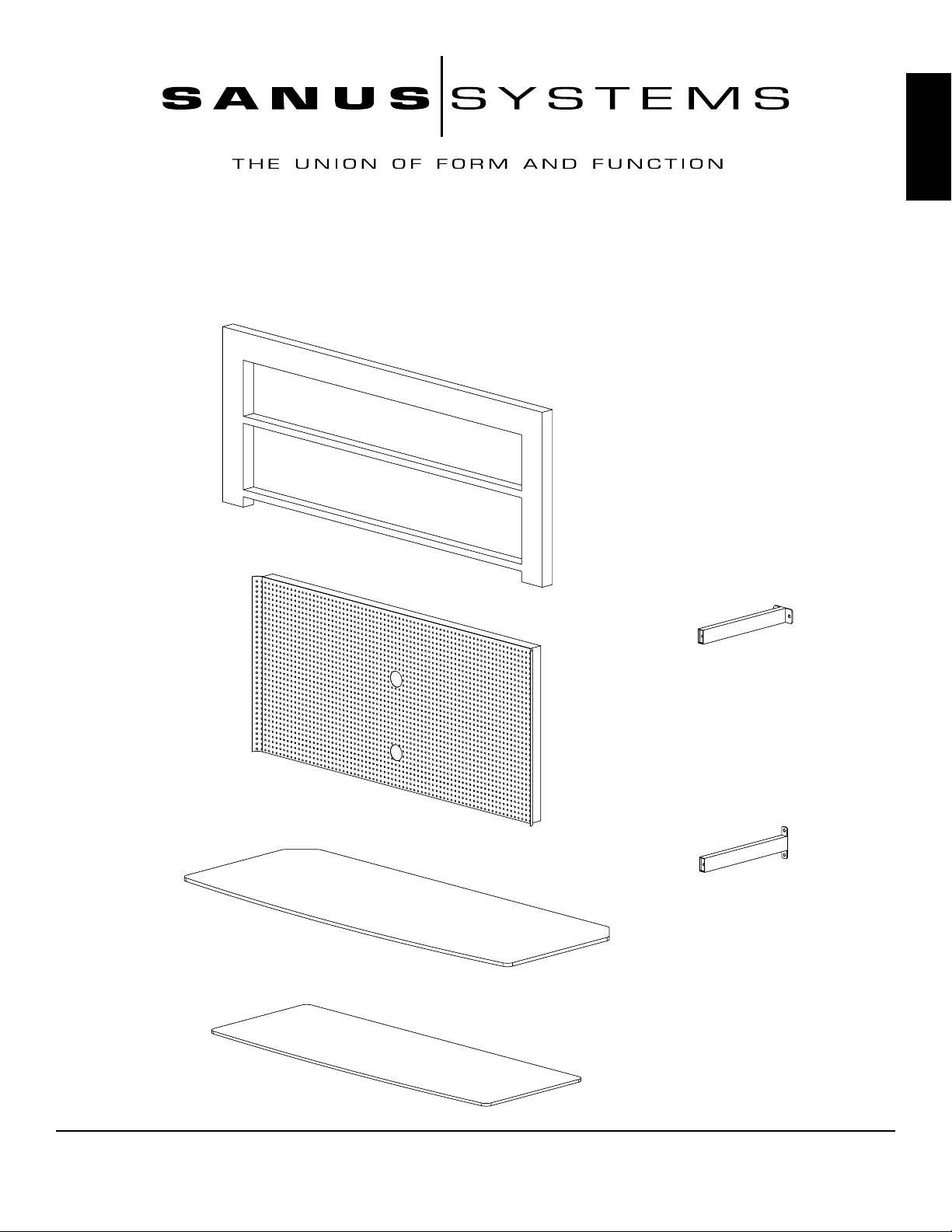
Parts and Hardware:
(1) Front Frame - a
(1) Upper Brace Bar - e
(1) Back Frame - b
(4) Lower Brace Bar - f
(1) Top Glass Shelf - c
(2) Glass Shelf - d
Sanus Systems 2221 Hwy 36 West, St. Paul, MN 55113 USA
800.359.5520 www.sanus.com
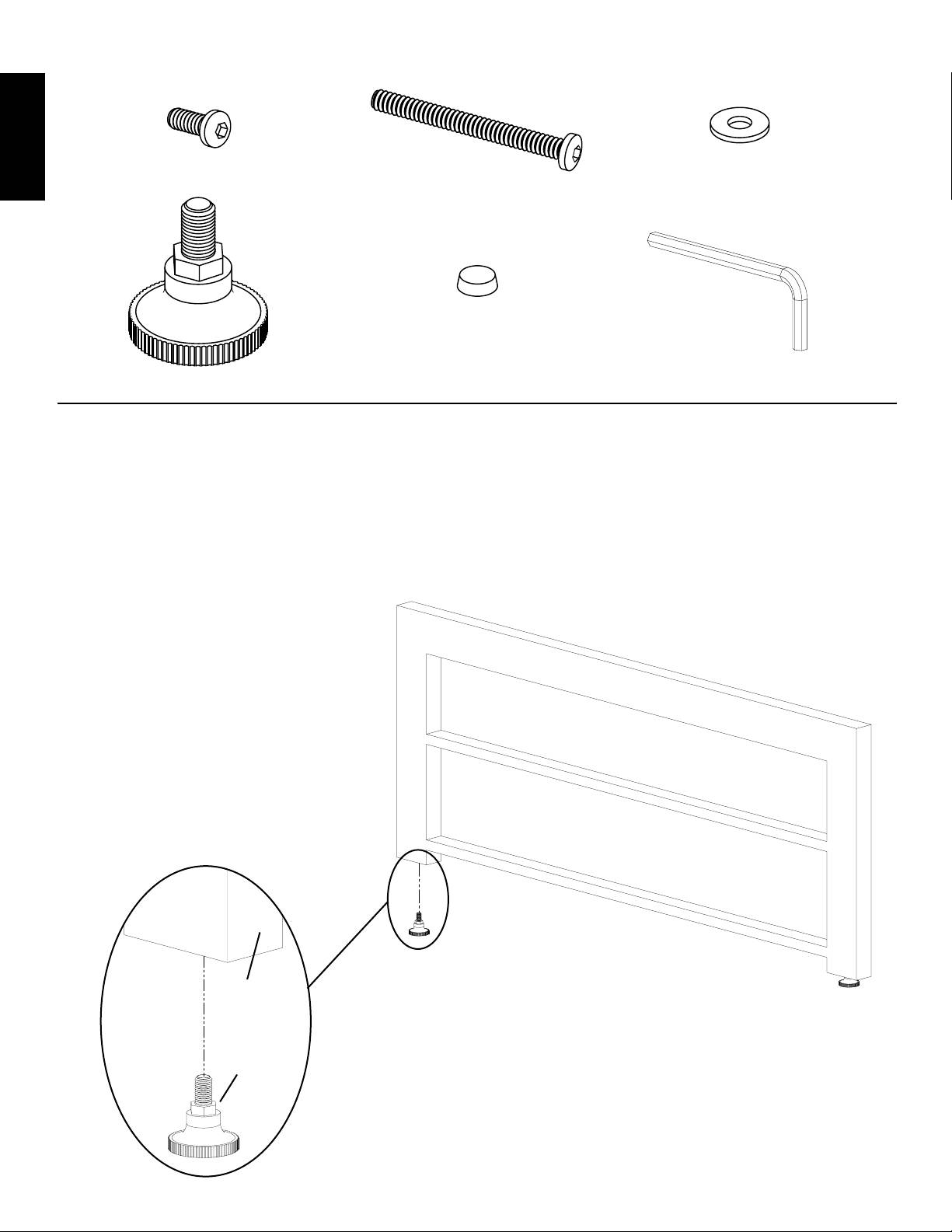
Hardware: Shown at actual size
ENGLISH
(10) Short Allen Bolt - g (5) Long Allen Bolt - h (5) Washer - i
(4) Foot - j (18) Glass Protector - k (1) Allen Key - l
Step 1: Install Feet
Thread 2 Feet (j) into the bottom of the Front Frame (a) as shown in Diagram 1. Thread the remaining two Feet into the bottom of the
Back Frame (b). Thread all 4 feet in until they bottom out in the frame.
Note: Once the stand is assembled, the Feet can be adjusted to level the stand if needed
Diagram 1
Detailed View
a
j
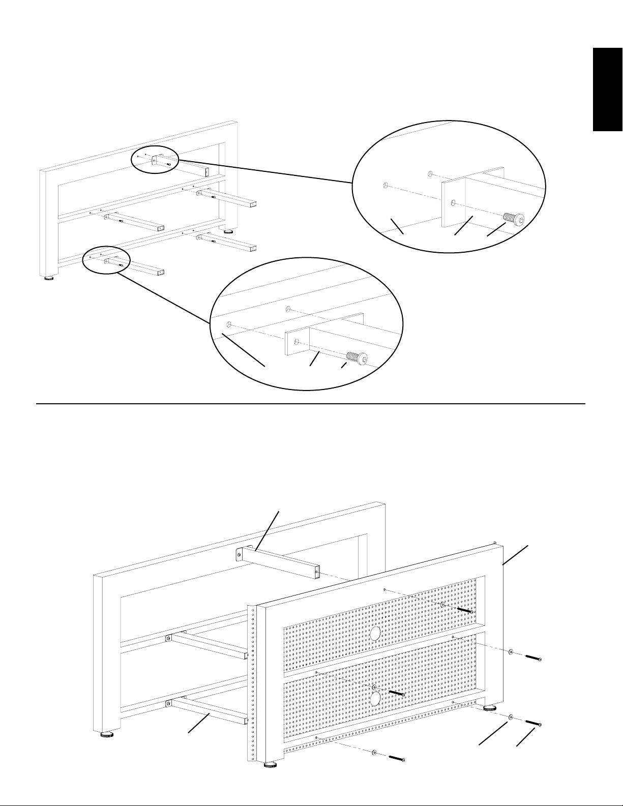
Step 2: Attach Brace Bars to Front Frame
ENGLISH
Thread a Short Allen Bolt (g) through each hole in the Upper Brace Bar (e) until the bar is secured to the Front Frame (a). See Detailed
View A of Diagram 2 for assistance. Proceed to thread a Short Allen Bolt through each hole in the Lower Brace Bars (f) so each bar is
secured to the Front Frame. See Detailed View B of Diagram 2 for assistance. Do not fully tighten the Short Allen Bolts at this time.
Detailed View A
Diagram 2
a e g
Detailed View B
a f g
Step 3: Attach Back Frame
Thread a Long Allen Bolt (h) through a Washer (i), the Back Frame (b), and into the back of the Brace Bar (e,f) as seen in Diagram 3. Repeat
process for each of the four remaining Long Allen Bolts. Make sure the stand is square and level. Once everything is positioned correctly,
proceed to tighten all of the Long Allen Bolts as well as the Short Allen Bolts (g) from Step 2 with the Allen Key (l) until they are tight.
e
Diagram 3
b
f
i h
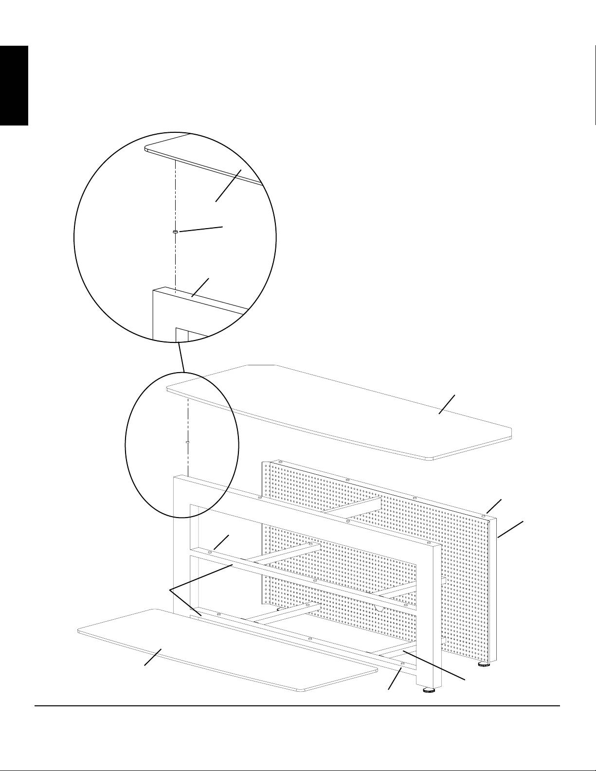
Step 4: Installing Glass Shelves
Evenly place 4 Glass Protectors (k) along the top, 3 along the middle crossbar and 3 more along the bottom of the Front Frame (a) as shown
in the Detailed View ofDiagram 4. Next, place a Glass protector on the back of each Lower Brace Bars (f). Then, evenly place 4 Glass
protectors on the top of the Back Frame (b). Next, place the Top Glass Shelf (c) on the top of the Front and Back Frame. Finally, place the
two Glass Shelves (d) so they rest on the Lower Brace Bars and the crossbars on the Front Frame. See Diagram 4 for assistance.
ENGLISH
Detailed View
c
k
a
Diagram 4
c
k
b
k
crossbar
d
f
k
