Hama VM3: инструкция
Раздел: Аксессуары для телевизоров
Тип:
Инструкция к Hama VM3
ENGLISH
ESPAÑOL DEUTSCH FRANÇAIS ITALIANO PYCCKO
Spanish German French Italian Russian Japanese Mandarin
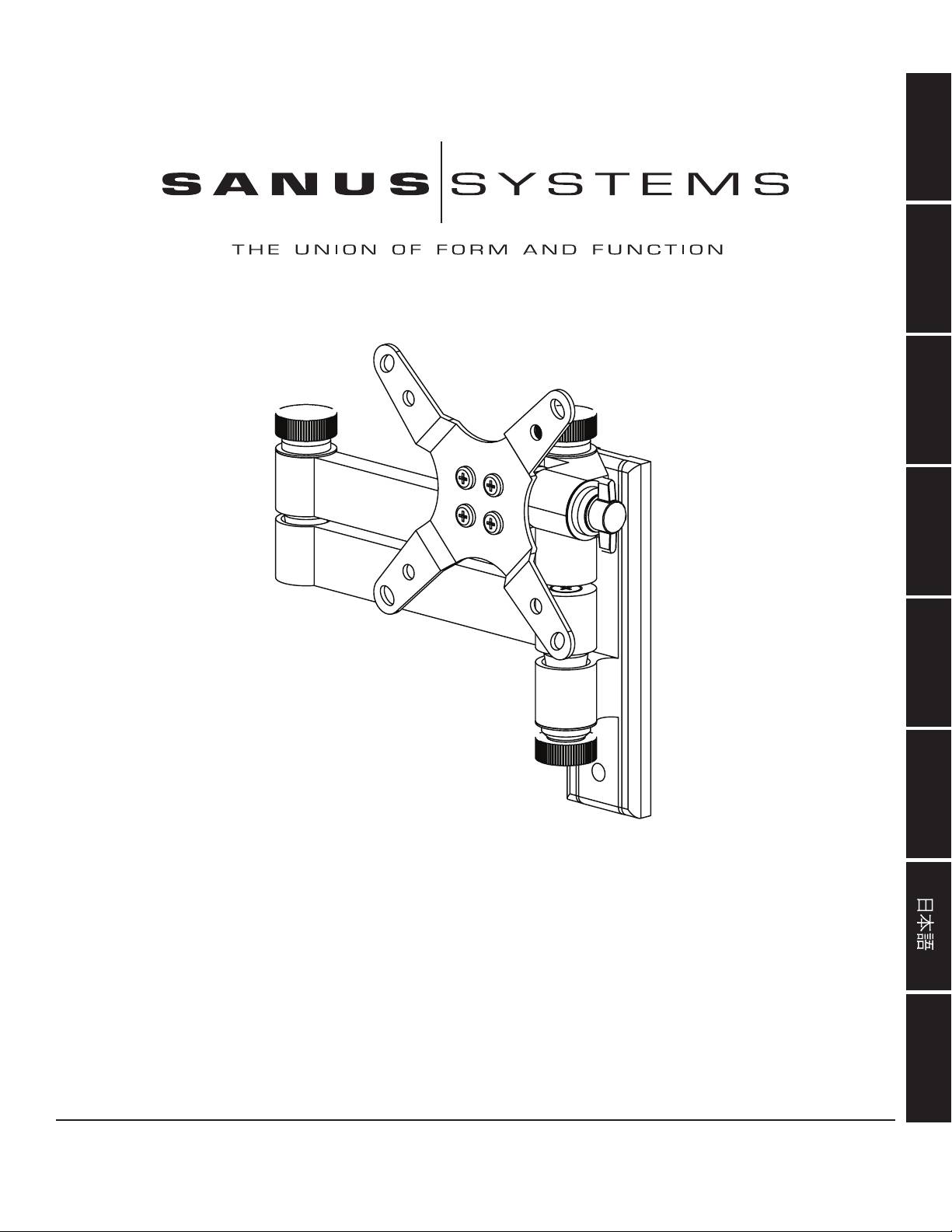
International Assembly Instructions for model VM3
中文
Sanus Systems 2221 Hwy 36 West, Saint Paul, MN 55113 7.05.05
Customer Service: (800) 359-5520 • (651) 484-7988 • fax (651) 636-0367
Customer Service Europe: 31 (0)20 5708938 • fax 31 (0)20 5708989
See complementary Sanus products at www.sanus.com

ENGLISH
Assembly Instructions for Model: VM3
Thank you for choosing Sanus Systems Vision Mount. This product is designed to
mount VESA 75/100 compatible LCD televisions up to 30 pounds onto a vertical wall.
It allows you to effortlessly tilt and swivel your new television up to 15° in either
direction as well as extend it up to 15” away from the wall without the use of tools.
Check carefully to make sure there are no missing or defective parts. Never use defec-
tive parts. Improper installation may cause damage or serious injury. If you do not
understand these directions, or have any doubts about the safety of the installation,
please call a qualied contractor or contact Sanus at 800.359.5520 or www.sanus.com.
We can quickly assist you with installation questions and missing or damaged parts.
Replacement parts for Sanus products purchased through authorized dealers will be
shipped directly to you.
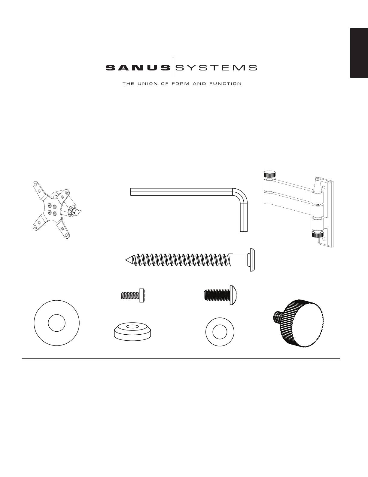
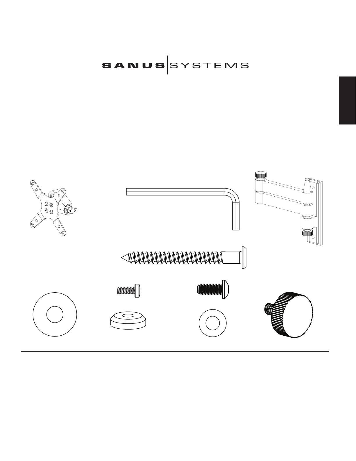
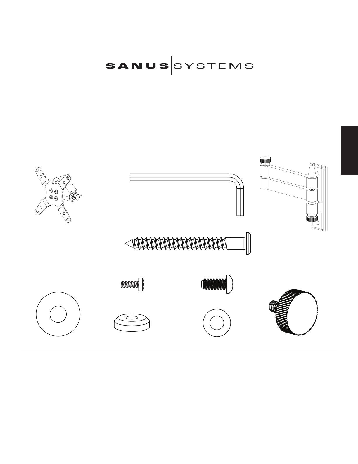
Required Tools: Drill with 3/16” bit, Phillips screw driver
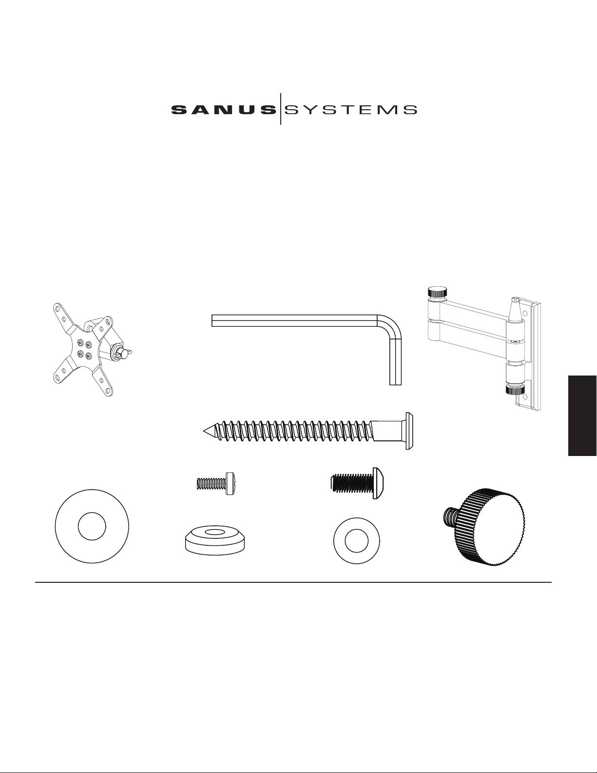
Parts and Hardware: *Not shown as actual size
(1) Allen Key - b
(1) Monitor Mount - a* (1) Wall Plate - c*
(2) Lag Bolt - d
(4) M4 x 10 Bolt - e (4) Knob Replacement Bolt - f
(1) Large Washer - g (1) Cap - h (1) Small Washer - i (1) Knob - j
Step 1 - Attaching to the Television: Attach the Monitor Mount (a) to the back of your LCD television using the M4 x 10 Bolt (e) as shown in Diagram 1. Place 4 bolts through the
Monitor Mount and tighten snugly into the VESA bolt mounting pattern on the back of the television. Make sure the large side of the tapered hole on the Monitor Mount faces toward
the bottom of the television.
Step 2 - Attaching to the Wall: Hardware for wood stud mounting is provided. For all other mounting applications contact a local contractor or hardware store. Use a high quality
stud sensor to locate a stud. It is a good idea to verify the stud location with an awl or thin nail as shown in Diagram 2a. Use the Wall Plate (c) as a template to mark the two hole loca-
tions on the wall. Make sure these holes are aligned vertically and centered over the stud. Pre-drill the two holes to a depth of 2.5” using a 3/16” drill bit. Attach the Wall Plate to the
wall using the two Lag Bolts (d) as shown in Diagram 2b. Tighten the Lag Bolts rmly with the Allen Key (b).
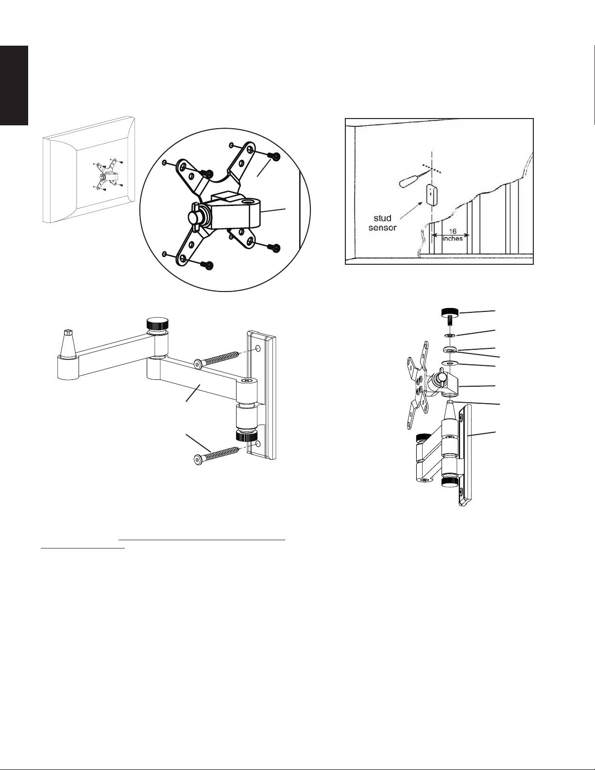
Diagram 1 Diagram 2a
ENGLISH
Detailed View
e
a
Diagram 2b Diagram 3
j
i
h
square cut in cap
g
a
c square end of
bushing
d c
Step 3 - Add Monitor Mount to Wall Plate: Once the LCD TV is attached to the
Monitor Mount (a), and the Wall Plate (c) is properly installed, set the tapered hole in
the Monitor Mount down over the cone shaped bushing on the Wall plate. This process
is shown without the TV in Diagram 3 so that you can see the parts more clearly. Make
sure the Monitor Mount is seated completely onto the Wall Plate. Add the Large Washer
(g). Next add the Cap (h). Make sure the square cut into the cap ts over the square
top of the Wall Plate bushing. Finally place the Knob (j) through the Small Washer (i),
the Cap and into the cone shaped bushing. You can now set each of the knobs to the
desired level of tension.
Note: For institutional or heavy load applications a Knob Replacement
bolt (f) may be used in place of each Knob and tightened with the Allen
Key provided. This will allow you to get greater tension while still being
able to adjust the position of your TV.
ESPAÑOL
Instrucciones de armado del modelo: VM3
Gracias por elegir el soporte Vision Mount de Sanus Systems. Este producto ha sido diseñado para
montar televisores con pantalla de cristal líquido compatibles con el modelo VESA 75/100 con un
peso de hasta 13,6 kg (30 lb) en una pared vertical. El mismo permite inclinar y girar fácilmente
el televisor hasta en 15 ° en cualquier dirección, al igual que extenderlo hasta 38,1 cm (15 pulg.)
de la pared si tener que utilizar herramientas. Revise cuidadosamente para asegurarse de que no
hayan piezas faltantes ni defectuosas. Nunca use piezas que presenten algún defecto. La instalación
incorrecta puede provocar daño o lesiones graves. Si no entiende estas instrucciones o si tiene alguna
duda con respecto a la seguridad de la instalación, llame a un contratista calicado o llámenos al
800.359.5520 (en EE.UU.) o al 31 (0) 20 5708938 (en Europa). También nos puede visitar en nuestro
sitio www.sanus.com. Podemos ayudarle rápidamente a responder sus preguntas sobre la instalación
o con respecto a las piezas faltantes o dañadas. Las piezas de repuesto para los productos Sanus
comprados a través de un distribuidor autorizado se enviarán directamente a usted.
Herramientas necesarias: Taladro con broca de 0,5 cm (3/16 pulg.), destornillador Phillips
Piezas y tornillería: *No es el tamaño real
(1) Llave allen - b
(1) Soporte de monitor - a* (1) Placa de pared - c*
(2) Tirafondo - d
(4) Perno M4 x 10 - e (4) Perno de reemplazo de perilla - f
(1) Arandela grande - g (1) Tapa - h (1) Arandela pequeña - i (1) Perilla - j
Paso 1 - Conexión al televisor: Conectar el soporte de monitor (a) a la parte trasera del televisor con pantalla de cristal líquido utilizando el perno M4 x 10 (e), como se ilustra en
el diagrama 1. Pasar 4 pernos por el soporte de monitor y apretarlos rmemente en la estructura de montaje VESA en la parte trasera del televisor. Asegurarse de que el lado grande del
agujero cónico en el soporte de monitor quede orientado hacia la base del televisor.
Paso 2 - Conexión a la pared: Se suministra la tornillería para el montaje en un pie derecho de madera. Para todas las demás aplicaciones de montaje, ponerse en contacto con
un contratista o una ferretería local. Utilizar un detector de vigas de alta calidad para localizar el pie derecho. Es una buena idea vericar la ubicación del pie derecho con un punzón
o clavo delgado, como se ilustra en el diagrama 2a. Utilizar la placa de pared (c) como una plantilla para marcar las dos posiciones de los agujeros en la pared. Asegurarse de que los
dos agujeros queden alineados verticalmente y centrados en el pie derecho. Perforar con antelación dos agujeros a una profundidad de 6,4 cm (2,5 pulg.) utilizando una broca de 0,5 cm
(3/16 pulg.) Conectar la placa en la pared con los dos tirafondos (d), como se ilustra en el diagrama 2b. Apretar rmemente los tirafondos con una llave allen (b).
L A U N I Ó N D E F O R M A Y F U N C I Ó N
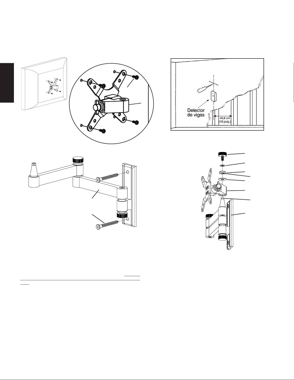
Diagrama 1 Diagrama 2a
Vista detallada
e
ESPAÑOL
a
Diagrama 2b Diagrama 3
j
i
h
corte cuadrado
g en la tapa
a
c extremo
cuadrado de
buje
d c
Paso 3 - Agregar el soporte de monitor a la placa de pared: Una vez que
el televisor con pantalla de cristal líquido se conecta en el soporte de monitor (a), y
la placa de pared (c) se instala correctamente, poner el agujero cónico del soporte de
monitor sobre el buje en forma de cono que se encuentra en la placa de pared. Este
proceso se muestra sin el televisor en el diagrama 3 para que las piezas puedan verse
más claramente. Asegurarse de que el soporte de monitor se asiente completamente en
la placa de pared. Agregar la arandela grande (g). Luego agregar la tapa (h). Asegurarse
de que el corte cuadrado de la tapa encaje en la parte superior del buje de la placa de
pared. Finalmente pasar la perilla (j) a través de la arandela pequeña (i) y la tapa e
insertarla en el buje en forma de cono. Ahora las perillas se pueden ajustar al nivel de
tensión deseado.
Nota: Para aplicaciones de carga pesada o en instituciones se puede
utilizar un perno (f) en reemplazo de cada una de las perillas. Apretar los
pernos con la llave allen suministrada. Esto permite obtener una mayor
resistencia y aún así poder ajustar la posición del televisor.
Montageanweisungen für das Modell: VM3
Wir freuen uns, dass Sie sich für ein Vision Mount-Produkt von Sanus Systems entschieden haben. Dieses Gerät ist für die Montagehalterung
VESA 75/100 und damit kompatible LCD-Fernseher mit einem Gewicht von bis 13,6 kg (30 lb) an einer vertikalen Wand vorgesehen. Mit
diesem Gerät lässt sich der neue Fernseher bis zu 15 ° in beliebiger Richtung neigen und schwenken sowie ohne Einsatz von Werkzeugen
bis zu 38,1 cm (15") von der Wand abziehen. Es dürfen keine Bauteile fehlen oder defekt sein. Verwenden Sie niemals beschädigte Teile!
Unsachgemäße Montage kann Schäden am Gerät und schwere Verletzungen hervorrufen! Wenn Sie diese Anweisungen nicht verstehen
oder Zweifel an der Sicherheit der Montage haben, rufen Sie einen Fachmann an oder kontaktieren Sie Sanus Systems telefonisch unter
+1-800-359-5520 (USA) oder +31-(0)20-570-8938 (Europa). Oder besuchen Sie uns im Internet unter www.sanus.com. Wir können
DEUTSCH
Ihnen bei Fragen zur Montage und zu beschädigten oder fehlenden Teilen schnell helfen. Ersatzteile für bei autorisierten Fachhändlern
gekaufte Sanus-Produkte werden direkt an Ihre Adresse versendet.
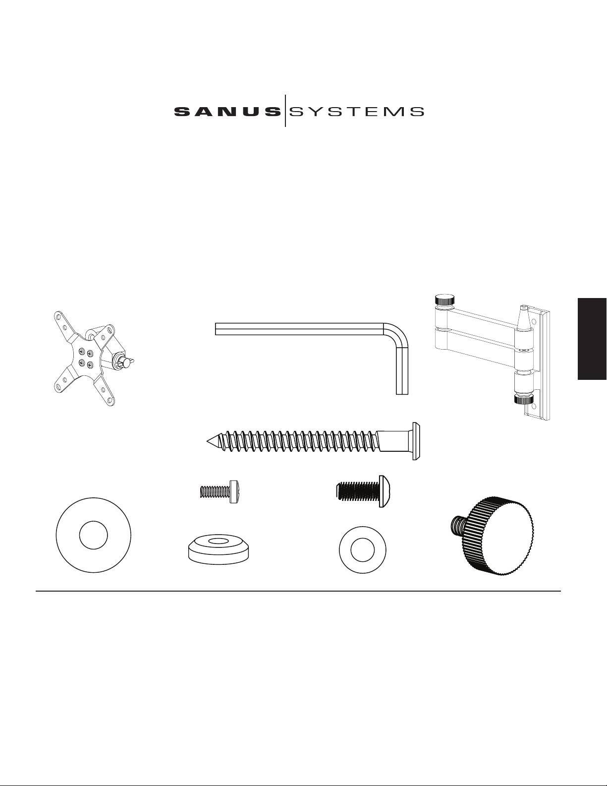
Erforderliche Werkzeuge: Bohrmaschine mit einem Bohrer 0,5 cm (3/16"), Kreuzschlitzschraubendreher
Teile und Zubehör: *Nicht maßstäblich dargestellt.
(1) Inbusschlüssel – b
(1) Monitorhalterung – a* (1) Wandplatte – c*
(2) Holzschraube – d
(4) Schraube M4 x 10 – e (4) Rändelersatzschraube – f
(1) Große Unterlegscheibe – g (1) Kappe – h (1) Kleine Unterlegscheibe – i (1) Rändelschraube – j
Schritt 1 – Anbau am Fernseher: Die Monitorhalterung (a) an der Rückseite des LCD-Fernsehers mit der Schraube M4 x 10 (e) wie in Abbildung 1 anbauen. Vier Schrauben durch
die Monitorhalterung schieben und fest in den VESA-Schraubanschluss an der Rückseite des Fernsehers eindrehen. Die große Seite der konischen Bohrung an der Monitorhalterung muss
zum Fernseherboden zeigen.
Schritt 2 – Anbau an der Wand: Es wird Zubehör für die Montage an einem Holzbalkenträger mitgeliefert. Bei allen anderen Montagevarianten die Teile im Fachhandel oder
beim Vertragshändler erwerben. Einen Träger mit einem hochwertigen Sensor suchen. Die Lage des Trägers kann am besten mit einer Ahle oder einem dünnen Nagel wie in Abbildung
2a überprüft werden. Die Wandplatte (c) als Vorlage zur Markierung der beiden Bohrungen an der Wand verwenden. Die beiden Bohrungen müssen vertikal und mittig auf den Träger
ausgerichtet sein. Die beiden Löcher bis zu einer Tiefe von 6,4 cm (2,5") mit einem Bohrer 0,5 cm (3/16") vorbohren. Die Wandplatte mit den beiden Holzschrauben (d) wie in Abbildung 2b
an der Wand montieren. Die Holzschrauben mit dem Inbusschlüssel (b) festziehen.
D I E E I N H E I T V O N F O R M U N D F U N K T I O N
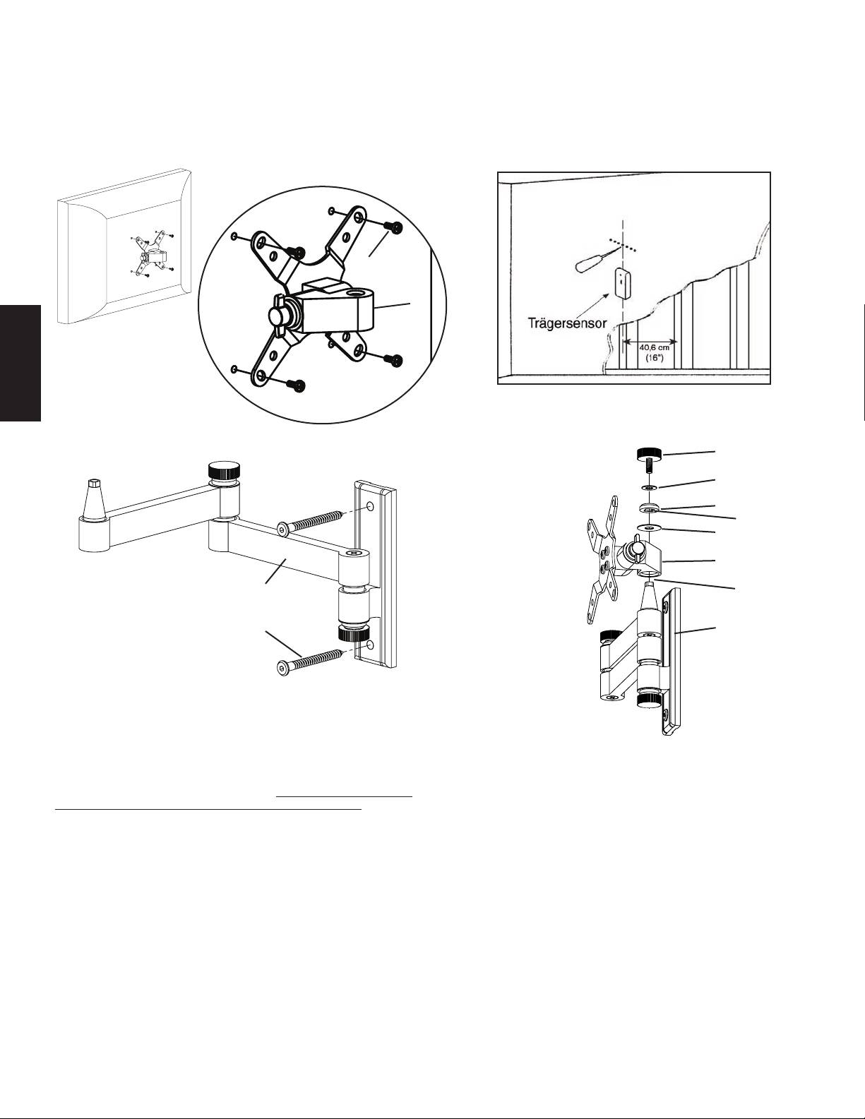
Abbildung 1 Abbildung 2a
Detailansicht
e
a
DEUTSCH
Abbildung 2b Abbildung 3
j
i
h
Vierkant-
g Aussparung
in der Kappe
a
c Vierkant-
Ende der
Buchse
d c
Schritt 3 – Anbau der Monitorhalterung an der Wandplatte: Sobald der
LCD-Fernseher an der Monitorhalterung (a) angebaut ist und die Wandplatte (c)
ordnungsgemäß installiert ist, die konische Bohrung in der Monitorhalterung über der
konischen Buchse der Wandplatte platzieren. In Abbildung 3 ist dieser Arbeitsschritt
ohne Fernseher dargestellt, so dass die Teile besser erkennbar sind. Die gesamte
Monitorhalterung muss sicher auf der Wandplatte sitzen. Die große Unterlegscheibe
(g) hinzufügen. Danach die Kappe (h) hinzufügen. Die Vierkant-Aussparung in der
Kappe muss auf die Vierkant-Oberseite der Wandplattenbuchse passen. Zuletzt die
Rändelschraube (j) durch die kleine Unterlegscheibe (i) und die Kappe in die konische
Buchse eindrehen. Jetzt können die Rändelschrauben wie gewünscht festgezogen
werden.
Hinweis: In öffentlichen Räumen oder bei starker Belastung kann anstelle
der Rändelschrauben eine Rändelersatzschraube (f) verwendet und mit
dem mitgelieferten Inbusschlüssel festgezogen werden. Auf diese Weise
lässt sich der Fernseher stärker festziehen und dennoch die Position
einstellen.
Instructions d’assemblage pour le modèle : VM3
Nous vous remercions d’avoir choisi un montant Vision Mount de Sanus Systems. Ce produit est conçu
pour xer au mur des téléviseurs LCD compatibles à VESA 75/100 d’un poids maximum de 13,6 kg
(30 lb). Il vous permet d’incliner et de faire pivoter sans effort votre nouveau téléviseur jusqu’à 15 °
dans n’importe quelle direction ainsi que de l’espacer de 38,1 cm (15 po) du mur sans utiliser d’outils.
Vériez soigneusement qu’il n’y a aucune pièce manquante ou défectueuse. N’utilisez jamais de
pièces défectueuses. Une installation incorrecte peut entraîner des dommages ou des blessures graves.
Si vous ne comprenez pas ces instructions ou si vous avez un doute quant à la sécurité de cette
installation, veuillez faire appel à un technicien qualié ou communiquez avec Sanus en composant
le 1-800-359-5520 (aux É.-U.), ou le 31 (0) 20 5708938 (pour l’Europe). Vous pouvez aussi allez sur
notre site Web au www.sanus.com. Nous pourrons répondre rapidement à toute question concernant
l’installation ou des pièces manquantes ou endommagées. Les pièces de rechange de produits Sanus
achetés auprès de distributeurs agréés vous seront livrées directement.
Outils nécessaires : Perceuse avec mèche de 0,5 cm (3/16 po), tournevis cruciforme
Les pièces et le matériel : *Non illustré en grandeur réelle
FRANÇAIS
(1) Clé Allen - b
(1) Support d’écran - a* (1) Plaque murale - c*
(2) Tire-fond - d
(4) Boulon M4 x 10 - e (4) Boulon de remplacement de bouton - f
(1) Grosse rondelle - g (1) Capuchon - h (1) Petite rondelle - i (1) Bouton - j
Etape 1 - Fixation au téléviseur : Fixez le support d’écran (a) à l’arrière de votre téléviseur LCD à l’aide du boulon M4 x 10 (e), tel qu’illustré au schéma 1. Insérez 4 boulons à
travers le support d’écran et serrez-les bien dans la conguration de montage VESA pour insertion de boulons à l’arrière du téléviseur. Assurez-vous que l’ouverture la plus large du trou
conique du support d’écran est orientée vers le bas du téléviseur.
Etape 2 - Fixation au mur : Le matériel de xation pour ossature de bois est fourni. Pour tous les autres montages, communiquez avec un entrepreneur local ou une quincaillerie.
Servez-vous d’un détecteur de montants de haute qualité pour repérer un montant. Il est préférable de vérier l’emplacement des montants à l’aide d’un poinçon ou d’un clou mince
tel qu’indiqué au schéma 2a. Servez-vous de la plaque murale (c) comme modèle pour marquer les deux emplacements de trous sur le mur. Assurez-vous que les trous sont alignés
verticalement et centrés sur le montant. Percez au préalable deux trous d’une profondeur de 6,4 cm (2,5 po) à l’aide d’une mèche de 0,5 cm (3/16 po). Fixez la plaque murale au mur à
l’aide des deux tire-fonds (d), tel qu’illustré sur le schéma 2b. Serrez les tire-fonds fermement à l’aide de la clé Allen (b).
L’ U N I O N D E L A F O R M E E T D E L A F O N C T I O N
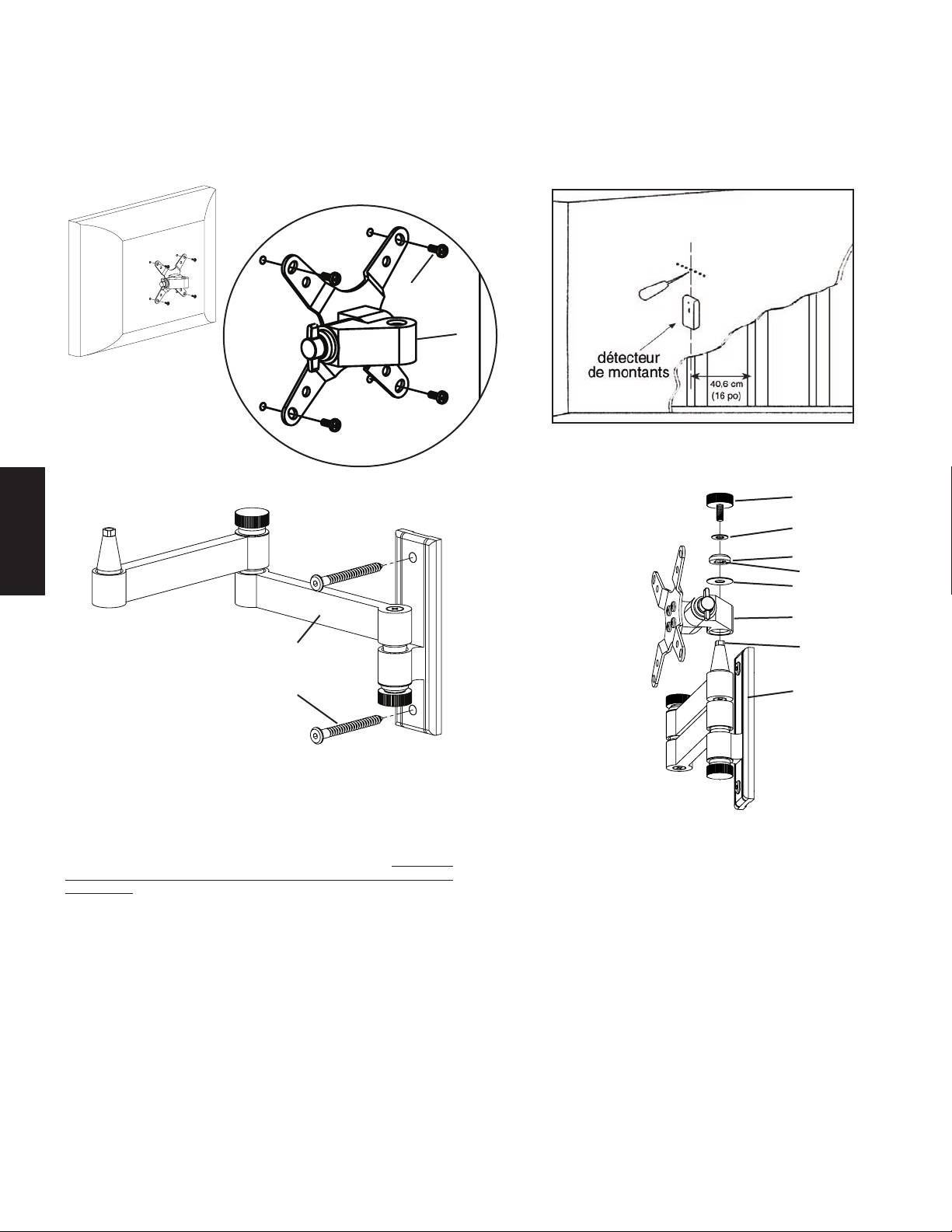
Schéma 1 Schéma 2a
Vue détaillée
e
a
Schéma 2b Schéma 3
j
i
h
ouverture carrée
FRANÇAIS
g du capuchon
a
c bout carré du
raccord
d c
Etape 3 - Ajout du support d’écran à la plaque murale : Une fois le téléviseur
LCD xé au support d’écran (a) et la plaque murale (c) correctement installée, placez
le trou conique du support d’écran sur le raccord conique de la plaque murale. Cette
procédure est illustrée sans le téléviseur sur le schéma 3 an que vous puissiez mieux
distinguer les pièces. Assurez-vous que le support d’écran est bien logé sur la plaque
murale. Ajoutez la grosse rondelle (g). Ajoutez ensuite le capuchon (h). Assurez-vous
que l’ouverture carrée du capuchon enveloppe bien le bout carré du raccord de la
plaque murale. Insérez enn le bouton (j) dans la petite rondelle (i), dans le capuchon
et dans le raccord conique. Vous pouvez à présent régler chacun des boutons au niveau
de tension voulu.
Remarque : Pour une installation dans un organisme institutionnel
ou prévue pour supporter une lourde charge, utilisez un boulon de
remplacement de bouton (f) à la place de chaque bouton et serrez-les à
l’aide de la clé Allen fournie. Ceci permettra d’avoir plus de tension tout
en étant capable de régler la position du téléviseur.
Istruzioni di montaggio per il modello: VM3
Grazie per aver scelto un prodotto Sanus Systems Vision Mount. Questo prodotto è
progettato per montare su pareti verticali televisori LCD compatibili VESA 75/100 no a
13,6 kg (30 libbre). In tal modo sarà possibile inclinare e orientare senza sforzi il nuovo
televisore no a 15 ° in ogni direzione oltre a estenderla no a 38,1 cm (15”) lontano dalla
parete senza usare strumenti. Controllare attentamente che non vi siano parti mancanti
o difettose. Non utilizzare parti difettose. L’installazione errata può causare danni o
lesioni gravi. Se non si comprendono queste istruzioni o si hanno dubbi sulla sicurezza
dell’installazione, rivolgersi a un installatore specializzato o contattare la Sanus al
numero verde USA 800.359.5520 o, in Europa, al numero +31 (0) 20 5708938. È anche
possibile visitare il sito www.sanus.com. Possiamo rispondere rapidamente alle domande
relative all’installazione o alle parti mancanti o difettose. Le parti di ricambio per i prodotti
Sanus acquistati attraverso i rivenditori autorizzati verranno spedite direttamente al cliente.
Strumenti necessari: trapano con punta da 0,5 cm (3/16”), cacciavite Phillips
Parti e minuteria: *in gura non delle dimensioni reali
(1) chiave a brugola – b
ITALIANO
(1) staffa per monitor - a* (1) piastra per parete - c*
(2) tirafondi – d
(4) bullone M4 x 10 - e (4) bullone per la sostituzione della manopola - f
(1) rondella grande - g (1) coprivite – h (1) rondella piccola – i (1) manopola - j
Fase 1 – Collegamento al televisore: collegare la staffa del monitor (a) sul retro del televisore LCD usando il bullone M4 x 10 (e) come mostrato nella Figura 1. Inserire i 4 bulloni
attraverso la staffa del monitor e serrare bene nella dima VESA di montaggio per bulloni presente sul retro del televisore. Assicurarsi che il lato largo del foro conico sulla staffa del
monitor sia rivolto verso la parte inferiore del televisore.
Fase 2 – Collegamento alla parete: in dotazione viene fornita la minuteria per il perno in legno. Per tutte le altre applicazioni di montaggio rivolgersi al rappresentante locale
o a un negozio di ferramenta. Usare un rilevatore di perni metallici di alta qualità per individuare eventuali pezzi metallici nella parete. È una buona idea vericare la posizione dei
pezzi metallici con un punteruolo o con un chiodo sottile come nella Figura 2a. Utilizzare la piastra a parete (c) come maschera per contrassegnare le posizioni dei due fori sulla parete.
Assicurarsi che questi fori siano allineati in verticale e centrati sopra al perno. Forare in precedenza i due fori ad una profondità di 6,4 cm (2,5”) usando una punta per trapano da 0,5 cm
(3/16”). Collegare la piastra per parete alla parete usando i due tirafondi (d) come mostrato nella Figura 2b. Serrare i tirafondi fermamente con la chiave a brugola (b).
L ' U N I O N E D I F O R M A E F U N Z I O N E
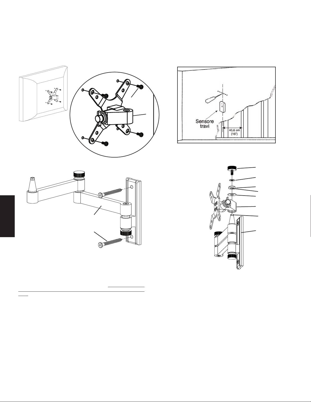
Figura 1 Figura 2a
Vista dettagliata
e
a
Figura 2b Figura 3
j
i
h
taglio quadrato
g nel coprivite
a
c estremità
quadrata della
boccola
ITALIANO
d c
Fase 3 – Aggiunta della staffa per monitor alla piastra per parete: una
volta che la TV a LCD è collegata alla staffa per monitor (a) e la piastra per parete
(c) è installata in modo corretto, posizionare il foro conico nella staffa per monitor in
basso verso la boccola conica sulla piastra per parete. Nella gura 3 questa operazione
è mostrata senza TV in modo da poter vedere le parti più chiaramente. Assicurarsi che
la staffa per monitor sia sistemata completamente sulla piastra per parete. Aggiungere
la rondella grande (g). Quindi aggiungere il coprivite (h). Assicurarsi che il taglio
quadrato nel coprivite si adatti alla parte quadrata della boccola della piastra per
parete. Inne inserire la manopola (j) attraverso la rondella piccola (i), nel coprivite e
nella boccola a forma di cono. A questo punto è possibile impostare ogni manopola al
livello di tensione desiderato.
Nota: per applicazioni in istituti o per usi gravosi è possibile usare un
bullone di ricambio per manopola (f) al posto di ogni manopola e serrare
con la chiave a brugola fornita. In tal modo la tensione è più alta mentre
è ancora possibile regolare la posizione della TV.
Инструкция по сборке крепления модели: VM3
Благодарим Вас за приобретение крепления для телевизора Sanus Systems Vision Mount. Крепление предназначено для установки жидкокристаллических
телевизоров, соответствующих стандарту VESA 75/100, весом до 13,6 кг (30 фунтов) на вертикальные стены. Устройство позволяет без усилий регулировать
ориентацию телеэкрана на угол до 15° в любом направлении, а также выносить его на расстояние до 38,1 cм (15") от стены без использования инструментов.
Тщательно проверьте наличие всех деталей и отсутствие заводского брака. Не используйте бракованные детали. Неправильная установка крепления связана
с опасностью травмирования людей и порчи имущества. Если Вам непонятны приведенные ниже инструкции, или если возникают любые сомнения по поводу
безопасности использования установленного устройства, обратитесь к квалифицированному специалисту или в компанию Sanus по телефону 800-359-5520
(США) или 31 (0) 20 5708938 (Европа). Вы также можете посетить наш веб-сайт www.sanus.com. Мы незамедлительно поможем Вам разрешить вопросы по
поводу установки устройства и недостающих либо поврежденных его частей. Запасные части к изделиям компании Sanus, приобретенным через уполномоченных
агентов по продаже, будут доставлены непосредственно по указанному Вами адресу.
Необходимые инструменты: Дрель со сверлом 0,5 cм (3/16"), отвертка Phillips.
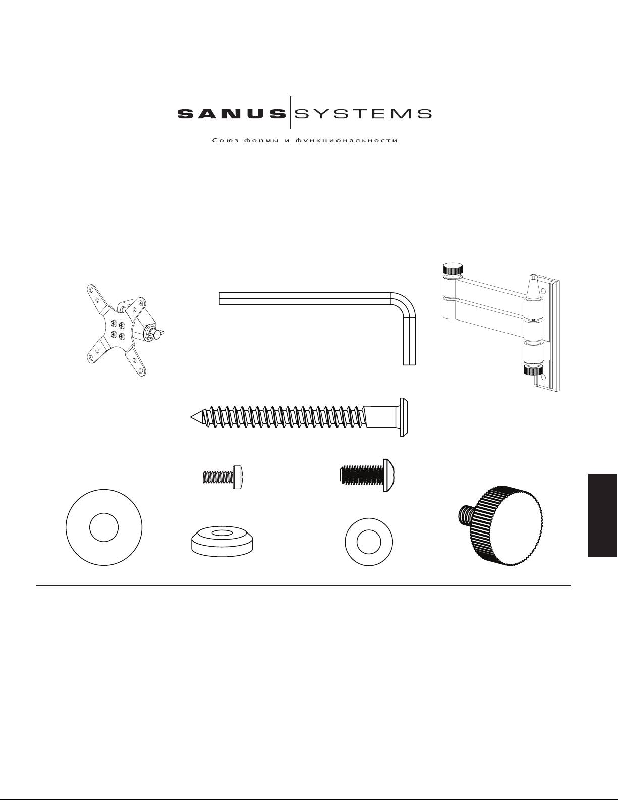
Детали устройства и инструменты: *Изображены в масштабе
Ключ торцовый (b) – 1 шт.
Крепежное устройство для монитора (a*) – 1 шт.
Настенная пластина (c*) – 1 шт.
Шуруп под ключ (d) – 2 шт.
PYCCKO
Винт M4 x 10 (e) – 4 шт. Винт для использования
вместо фиксирующей ручки (f) - 4 шт.
Большая шайба (g) – 1 шт. Колпачок (h) – 1 шт. Малая шайба (i) – 1 шт. Фиксирующая ручка (j) – 1 шт.
Шаг 1 - Прикрепление устройства к телевизору: Прикрепите крепежное устройство для монитора (a) к задней панели жидкокристаллического телевизора
посредством винта M4 x 10 (e), как показано на рисунке 1. Четыре винта следует завинтить через отверстия в крепежном устройстве в крепежный блок VESA и
туго затянуть. Коническое отверстие в крепежном устройстве должно быть обращено широкой стороной к нижней части телевизора.
Шаг 2 - Прикрепление устройства к стене: Устройство предназначено для крепления исключительно к деревянным стойками каркасных стен. Если
требуется прикрепить устройство к иной несущей конструкции, обратитесь к региональному дистрибьютору или в магазин бытовой техники. Для
определения местонахождения деревянной стойки следует использовать высокочувствительный датчик. Целесообразно проверить, правильно ли определено
местонахождение стойки, с помощью шила или тонкого гвоздя, как показано на рисунке 2а. Отметьте две точки, в которых следует просверлить в стене
отверстия, используя в качестве шаблона настенную пластину (c). Отверстия должны находиться на вертикальной линии и по центру деревянной стойки.
Сначала просверлите с помощью сверла 0,5 cм (3/16"), два черновых отверстия глубиной 6,4 см (2,5"). Прикрепите пластину к стене посредством двух шурупов
под ключ (d), как показано на рисунке 2b. Крепко затяните шурупы с помощью торцового ключа (b).
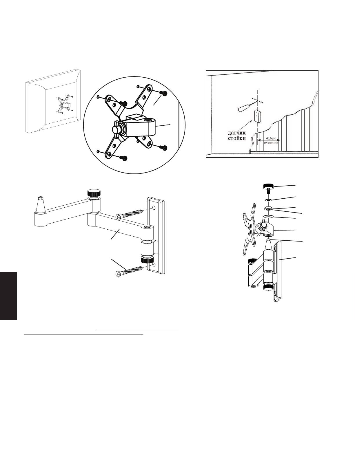
Рисунок 1 Рисунок 2а
Увеличенное изображение
e
a
Рисунок 2b Рисунок 3
j
i
h
квадратная
g прорезь
в колпачке
a
c квадратная
головка
втулки
d c
Шаг 3 - Установка крепежного устройства на настенную пластину После того,
как к жидкокристаллическому телевизору прикреплено крепежное устройство
(a), а настенная пластина (c) надлежащим образом установлена, следует насадить
отверстие конического профиля в крепежном устройстве на соответствующую
PYCCKO
коническую втулку в настенной пластине. На рисунке 3 эти действия показаны
без телевизора для большей наглядности. Крепежное устройство должно
полностью сесть на настенную пластину Wall Plate. Установите большую шайбу
(g). Затем насадите колпачок (h). Квадратная прорезь в колпачке должна
сесть на квадратную головку втулки настенной пластины. Затем завинтите
фиксирующую ручку (j) через маленькую шайбу (i) и колпачок в коническую
втулку. Теперь можно затянуть каждую фиксирующую ручку нужным образом.
Примечание: Если устройство планируется использовать в общественных
учреждениях или под значительной нагрузкой, вместо каждой фиксирующей
ручки можно использовать винт (f). Винты следует затягивать с помощью
торцового ключа. Благодаря использованию винтов соединения можно будет
сильнее затянуть, не ограничивая возможностей регулировки ориентации
телеэкрана.
VM3 モデルの組み立て説明書
Sanus Systems Vision Mount 製品をお買い上げいただきありがとうございま
す。本製品は、13.6 Kg (30 lbs)までの VESA 75/100 対応液晶テレビを垂直
な壁面に取り付けるよう設計されています。当製品の利用により、新型のテレビを
道具なしでも最大 15 度まであらゆる方向に傾けたり、回転させたり、また、最高
38.1 cm (15インチ) まで壁から離すことができます。不足や破損している部品が
ないかよく確認してください。破損した部品は絶対に使用しないでください。設置
方法が不適切な場合、破損や深刻なケガを引き起こすおそれがあります。ここに記
載されている説明ではよくわからない場合、もしくは設置上の安全性について疑問
がある場合は、有資格の契約業者にお電話いただくか、Sanus (米国: 800-359-
5520 もしくは、ヨーロッパ: 31-(0)-20-5708938) までご連絡ください。弊社ウ
ェブサイト www.sanus.com もご覧いただけます。指定販売店でお求めいただい
た製品については、交換部品をお客様に直接お届けいたします。
必要な工具: 0.5 cm (3/16 インチ) のビットついたドリル、プラスドライバー
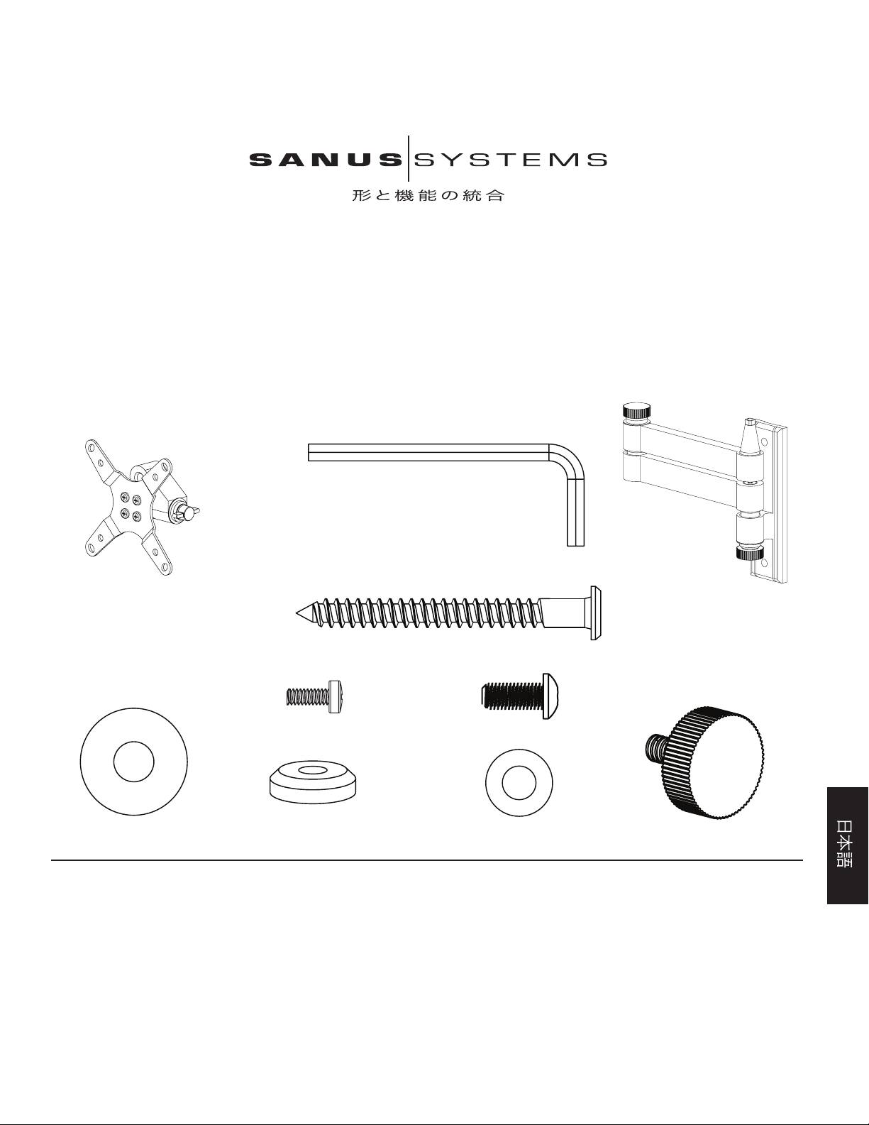
部品および金具:*表示は実サイズではありません。
(1) アレンキー - b
(1) モニターマウント - a* (1) 壁面プレート - c*
(2) ラグボルト- d
(4) M4 x 10 ボルト - e (4) ノブ取り換えボルト - f
(1) ワッシャー (大) - g (1) キャップ - h (1) ワッシャー (小) - i (1) ノブ - j
順序 1- テレビに取り付ける:図 1 のように、M4 x 10 ボルト (e) を使ってモニターマウント (a) を液晶テレビの背面に取り付けます。4 本のボルトを、モニターマウントに通し、テ
レビの背面の VESA 規格のボルトの取り付け位置にぴったり合わせて締めつけます。モニターマウントのテーパー穴の広がっている方がテレビの下部に向いていることを確認しま
す。
順序 2- 壁面に取り付ける:木製の間柱に取り付けるための金具が同梱されています。木製の間柱以外に取り付ける場合は、お近くの契約業者あるいは工具店にお問い合わせくだ
さい。高性能の間柱探知機を使って、間柱の位置を調べます。図 2a のように、千枚通しか細い釘で間柱の位置を再確認しておくとよいでしょう。壁面プレート (c) をテンプレートに
して、壁に開ける 2 つの穴の位置に印を付けます。 2 つの穴が垂直に並び、かつ間柱の中央にあることを確認します。 0.5 cm (3/16 インチ)インチのドリルビットを使って、奥行き
6.4 cm (2.5 in.) の穴を予め開けておきます。図 2b のように、2 本のラグボルトを使って、壁面プレート(d)を壁に取り付けます。アレンキー (b) を使って、ラグボルトをしっかりと
固定します。
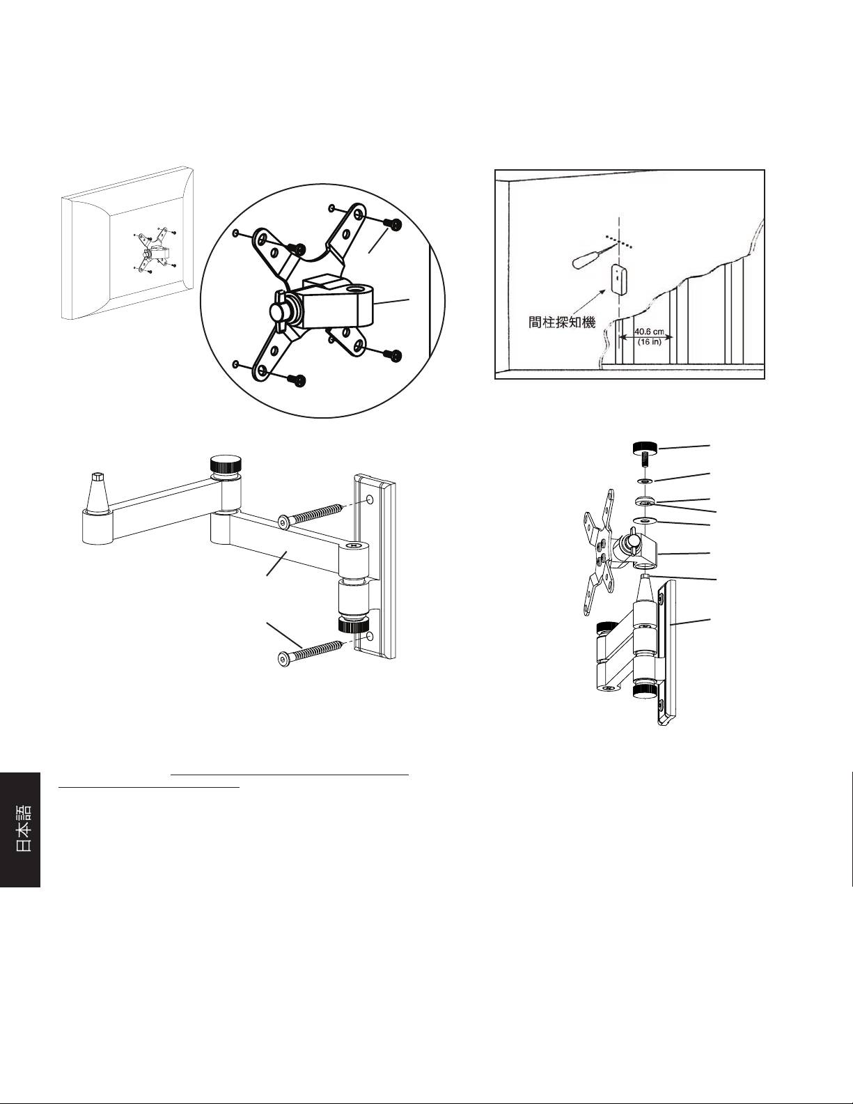
図 1 図 2a
詳細図
e
a
図 2b 図 3
j
i
h
キャップの四角穴
g
a
c ブッシュの
四角い先端部
d c
順序 3 - モニターマウントを壁面プレートに取り付ける:液晶テレビをモニターマ
ウント (a) に取り付け、壁面プレート (c) を正しく設置したら、モニターマウントの
テーパー穴を下向きにして円錐型ブッシュ上に載せます。 図 3 は、テレビを省いて
この操作の部品を見やすくしたものです。モニターマウントが完全に壁面プレート
の上に載っていることを確認します。その上にワッシャー (大) (g) を載せます。次に
キャップ (h) を載せます。キャップの四角穴が、壁面プレートのブッシュの四角い先
端部の上にはまっていることを確認します。最後にノブ (j) をワッシャー (小) (i) と
キャップに通して、円錐形ブッシュに取り付けます。ここで、各ノブを適当な締め具合
に調整できます。
注意:施設でのご利用または使用頻度が高い場合は、各ノブの代わりにノブ取り
換えボルト (f) を使用し、付属のアレンキーで固定します。 取り換えボルトを使う
と、さらに固く締めても、テレビの位置を調節することができます。
VM3 型号装配说明
感谢您选用 Sanus Systems Vision Mount。此产品设计用于将 VESA 75/100 可
兼容液晶电视机安装到垂直墙面上,承重达 约 13.6 公斤 (30 磅)。使用此产品
后,您不必使用任何工具就可毫不费力地以 15°角在任意方向上倾斜或旋转新
电视机,还可将其伸展离墙体至 15 厘米 (38.1 英寸)。请仔细检查以确保零件无
缺少或缺陷。切勿使用有缺陷的零件。安装不正确可能会导致损坏或严重受
伤。如果您不理解这些说明或对安装的安全性有任何疑问,请致电有资格的承包
商或与 Sanus 联系,联系电话: 800.359.5520 (美国)或 31 (0) 20 5708938 (欧洲)。
您也可以访问我们的网站 www.sanus.com。我们会迅速为您的安装问题提供协
助,以及解决零件缺少或损坏的问题。对通过授权经销商所购 Sanus 产品的替
换零件将直接送货上门。
必需的工具:带 0.5 厘米 (3/16 英寸) 钻头的钻孔机,Phillips 螺丝刀
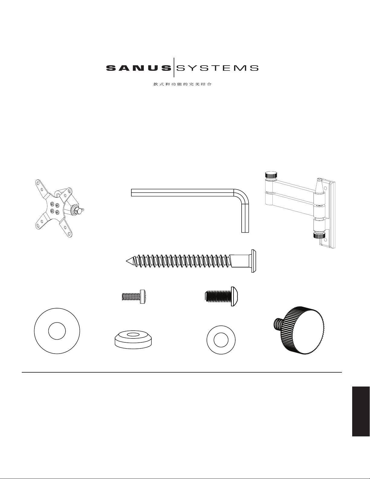
零件和五金件:*非实物大小
(1) 内六角扳手 - b
(1) 显示器架 - a* (1) 墙板 - c*
(2) 方头螺栓 - d
(4) M4 x 10 螺钉 - e (4) 旋钮替换螺钉 - f
(1) 大垫圈 - g (1) 顶盖 - h (1) 小垫圈 - i (1) 旋钮 - j
步骤 1 - 安装到电视机上:使用 M4 x 10 螺钉 (e) 将显示器架 (a) 安装到液晶电视机背面。将 4 枚 螺钉穿过显示器架,然后紧紧旋入电视机背面的 VESA 螺钉安装框架
中 (如图 1 所示)。请确保显示器架上锥孔的长边朝向电视机的底部。
步骤 2 - 安装到墙上:提供木立筋安装所需的五金件。其它安装所需的工具请联系当地的承包商或者从五金店购买。使用高质的墙筋传感器找到墙筋。最好先使用锥子
或者细钉确定墙筋的位置(如图 2a 所示)。将墙板 (c) 作为模板先在墙上标出两个孔的位置。请确保这两个孔垂直对齐,并位于墙筋的中心。使用 0.5 厘米 (3/16 英寸)
中文
钻头预先钻出两个 6.4 厘米 (2.5 英寸) 深的孔。使用两个方头螺栓 (d) 将墙板安装到墙上 (如图 2b 所示)。 最后使用内六角扳手 (b) 旋紧方头螺栓。
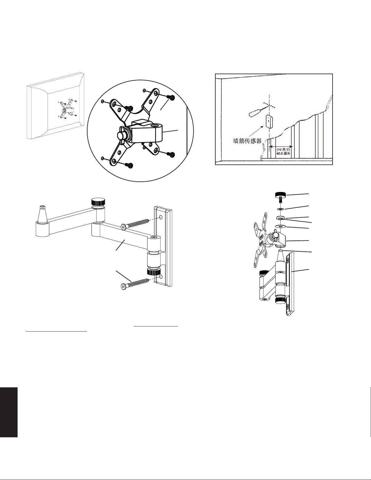
图 1 图 2a
详细视图
e
a
图 2b 图 3
j
i
h
方形内切顶盖
g
a
c 轴衬的方形
末端
d c
步骤 3 - 安装显示器架到墙板上:液晶电视机上安装了显示器架 (a) 并且墙板
(c) 正确安装到墙面上后,将显示器架上的锥孔向下套入墙板上的锥形轴衬。 表
示此过程的图 3 未显示电视机以便使您看清各零件。请确保显示器架在墙板上
完全安放到位。安放大垫圈 (g)。然后再安放顶盖 (h)。请确保顶盖的方形内切
口与墙板轴衬的方形末端相吻合。最后,将旋钮 (j) 穿过小垫圈 (i) 和顶盖旋入
锥形轴衬内。现在您可将每个旋钮调整至所需的绷紧度。
注意:对于机构安装或者重负荷安装,旋钮替换螺钉 (f) 将取代每个旋钮,并
使用所提供的内六角扳手将其旋紧。这样螺钉可旋得更紧,但是不影响对电视
机位置的调整。
