Hama VMPR1: инструкция
Раздел: Аксессуары для телевизоров
Тип:
Инструкция к Hama VMPR1
ENGLISH
ESPAÑOL DEUTSCH FRANÇAIS ITALIANO PYCCKO
Spanish German French Italian Russian Japanese Mandarin
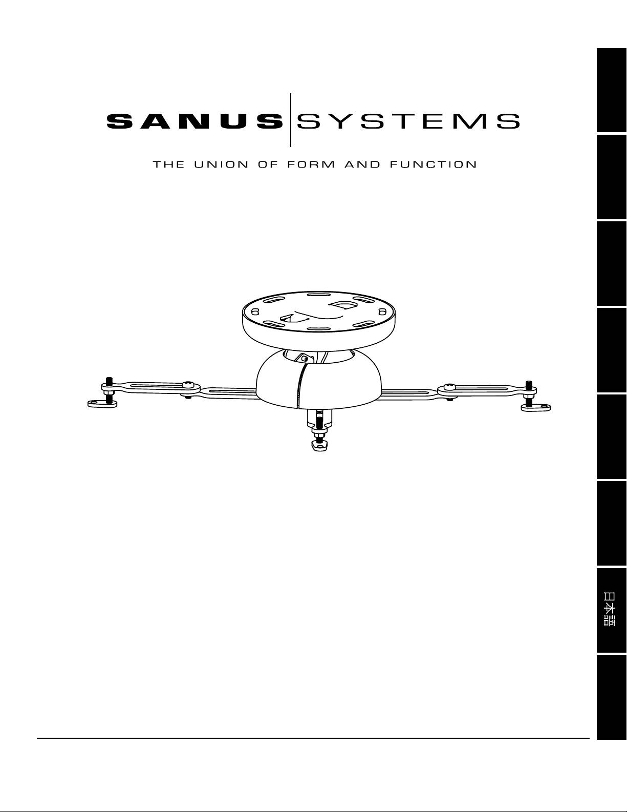
International Assembly Instructions for model VMPR1
中文
Sanus Systems 2221 Hwy 36 West, Saint Paul, MN 55113 USA 06.07.06
Customer Service: (800) 359-5520 • (651) 484-7988 • fax (651) 636-0367
Customer Service Europe: 31 (0)20 5708938 • fax 31 (0)20 5708989
See complementary Sanus products at www.sanus.com

ENGLISH
Assembly Instructions for Model: VMPR1
Thank you for choosing a Sanus Systems Model: VMPR1 ceiling mount. The VMPR1 ceiling mount provides a unique, simplied method
of ceiling mounting inverted LCD/DLP projectors. Its low prole design offers roll, pitch, and yaw adjustment. The VMPR1 steel-to-steel
construction with adjustable height to maintain proper ventilation, hold registration for quick lamp changes and easy lter cleaning without
loosing registration. The VMPR1 ceiling mount includes an NPT Extension Pipe that may be used where more room is required, such as
areas with vaulted or cathedral ceilings.
WARNING: The maximum weight to be installed on the VMPR1 ceiling mount is 50 pounds [22.68 Kg]. Improper installation may
result in serious personal injury. Make sure the structural members can support a redundant weight factor ve times the total
weight of the equipment. If the structure can not support this weight, reinforce the structure prior to installing the VMPR1.
If you do not understand these directions, or have any doubts about the safety of the installation, please call a qualied contractor or
contact Sanus at 800.359.5520 or www.sanus.com. Check carefully to make sure that there are no missing or defective parts. Our
customer service representatives can quickly assist you with installation questions and missing or damaged parts. Replacement parts
for products purchased through authorized dealers will be shipped directly to you. Never use defective parts. Do not use this product
for any purpose that is not explicitly specied by Sanus Systems. Please call Sanus Systems before returning products to the point of
purchase.
CSAV, Inc. and its afliated corporations and subsidiaries (collectively, “CSAV”), intend to make this manual accurate and complete.
However, CSAV makes no claim that the information contained herein covers all details, conditions, or variations. Nor does it provide for
every possible contingency in connection with the installation or use of this product. The information contained in this document is sub-
ject to change without notice or obligation of any kind. CSAV makes no representation of warranty, expressed or implied, regarding the
information contained herein. CSAV assumes no responsibility for accuracy, completeness or sufciency of the information contained in
this document.
Required Tools: Open End Wrenches, Phillips screwdrivers, Allen Wrenches (provided), other tools may be required depending on the
method of installation.
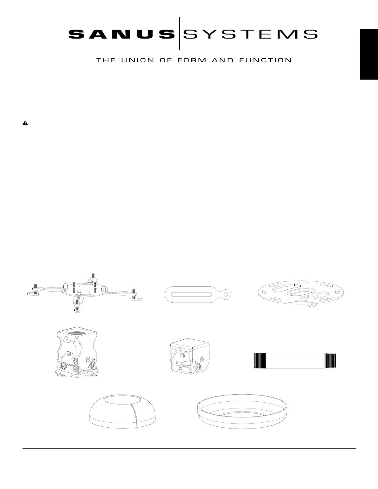
Supplied Parts and Hardware: (All threaded fasteners are shown full size.)
Universal Projector Interface - A
Extension Arm - B
Ceiling Plate - C
Qty. 1
Qty. 2
Qty. 1
Adjustment Bracket - D
NPT Adapter - E
NPT Extension Pipe - F
Qty. 1
Qty. 1
Qty. 1
Bottom Cover - G
Top Cover - H
Qty. 1
Qty. 1
Sanus Systems 2221 Hwy 36 West, Saint Paul, MN 55113 USA (6901-100023)
Customer Service: 800.359.5520. See complementary Sanus products at www.sanus.com
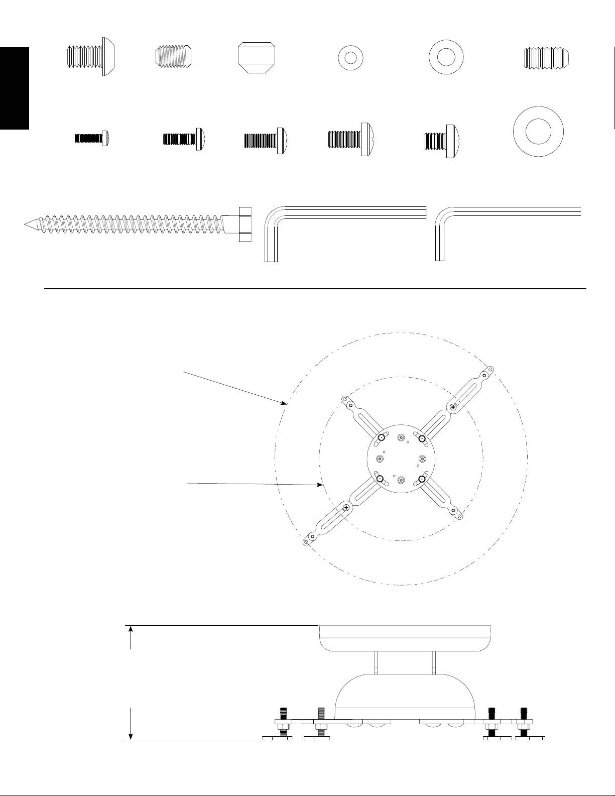
Cap Screw - I
Set Screw - J
Tapered Nut - K
M3/M4 Washer - L
M5/M6 Washer - M
Set Screw - N
Qty. 1
Qty. 1
Qty. 4
Qty. 4
Qty. 4
Qty. 1
ENGLISH
M3 x 10 mm - O
M4 x 12 mm - P
M5 x 12 mm - Q
M6 x 12 mm - R
M6 x 8 mm - S
Lag Bolt Washer - T
Qty. 4
Qty. 4
Qty. 4
Qty. 4
Qty. 2
Qty. 2
Lag Bolt - U
Allen Key - V
Allen Key - W
Qty. 2
Qty. 1
Qty. 1
VMPR1 Dimensional Drawings
[470.15 mm]
18.51 in
Covering area with
Extension Arms (B)
installed
[305.07 mm]
12.01 in
Covering area without
Extension Arms (B)
installed
[117.348 mm]
4.62 in
TO
[100.076 mm]
3.94 in
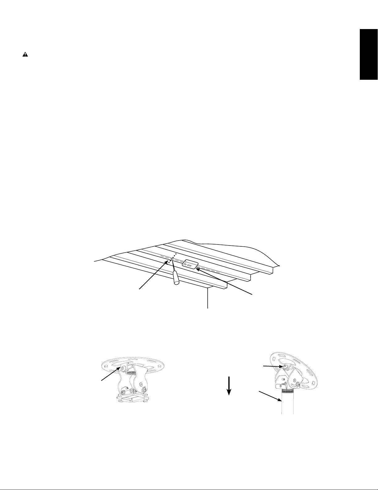
Step 1: Ceiling Preparation
ENGLISH
NOTE: Study the following information and adapt it as necessary to t your specic installation.
WARNING: The maximum weight to be installed on the VMPR1 ceiling mount is 50 pounds [22.68 Kg]. Improper
installation may result in serious personal injury. Make sure the structural members can support a redundant
weight factor ve times the total weight of the equipment. If the structure can not support this weight, reinforce the
structure prior to installing the VMPR1.
Determine the position of the mount and its distance from the screen. This will require knowing the lens to screen distance.
This information is normally listed in the projector specications for set-up.
The hardware provided with the VMPR1 is designed to be secured to a wood framing member. For installations other than
this, consult a qualied contractor. Use a high quality Stud Sensor to locate a stud in the area that you plan to mount the
VMPR1 as shown in Diagram 1A. Verify the stud location with an awl or thin nail.
NOTE: Do not attach the Ceiling Plate (C) at this time.
Flat Ceilings: Align the Ceiling Plate (C) with the two tabs aligned to the screen as shown in Diagram 1B.
Pre-drill a 3 in [76.2 mm] deep hole in the center of the framing member using a 3/16 in drill; then, using the Ceiling Plate
(C) as a template, pre-drill a second hole to the same depth.
Cathedral or Vaulted Ceilings: Align the Ceiling Plate (C) so that the NPT Adapter (E) is angled to allow the NPT Extension
Pipe (F) to point straight down as shown in Diagram 1C.
Pre-drill a 3 in [76.2 mm] deep hole in the center of the framing member using a 3/16 in drill; then, using the Ceiling Plate
(C) as a template, pre-drill a second hole to the same depth.
Diagram 1A
406.4 MM
16 IN
Sensor
Stud
Use awl or thin nail
to verify center of
Use Stud Sensor
framing member.
to locate framing
member.
Diagram 1B
Diagram 1C
(Shown assembled
(Shown assembled
for reference only.)
for reference only.)
Tab aligned to allow
NPT Extension Pipe (F)
Tab toward screen
to point down.
to allow adequate
Pitch Adjustment.
F
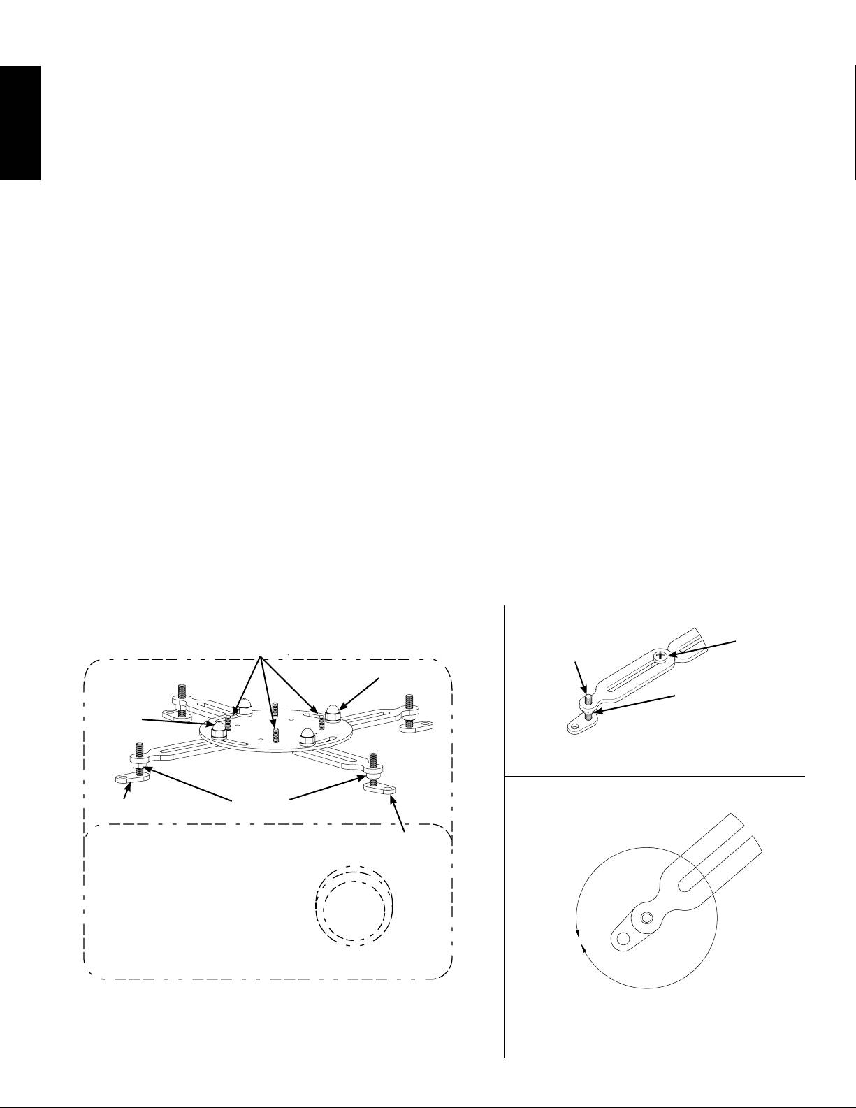
Step 2: Attach Universal Projector Interface to Projector
Loosen, but do not remove the Acorn Nuts shown in Diagram 2A.
Place the Universal Projector Interface (A) on the projector, aligning the holes in the Adjustable Feet with the threaded holes
in the projector and with the Threaded Studs in line as shown in Diagram 2A. If there are only three mounting points, remove
one Leg from the Universal projector Interface by removing the Acorn Nut.
ENGLISH
If necessary, add Extension Arms (B) to the Universal Projector Interface (A) by removing the Adjustable feet and Installing
them on the Extension Arms as shown in Diagram 2B.
Secure the Extension Arms (B) to the Universal Projector Interface, using the M6 x 8 mm (S) screws as shown in
Diagram 2B.
Adjust the Adjustable Feet as shown in Diagram 2C, making sure to allow for proper air ventilation and keeping the Universal
Projector Interface level with the projector. Some Adjustable Feet may need to be at different heights.
NOTE: If the mounting holes are closer than a ve inch diameter, lower the feet all the way to allow the Threaded
Stud to swing under the Ceiling Plate (C).
Determine the proper screw size and depth, M3 x 10 mm (O), M4 x 12 mm (P), M5 x 12 mm (Q), or M6 x 12 mm (R), and
corresponding Washers (L, M) for projector mounting.
Using correct Screws (O,P,Q,R) and Washers (L,M), secure the back two legs of the Universal Projector Interface (A) to the
projector; then, secure the front legs.
Move the Universal Projector Interface (A) to the center of gravity of the projector. You can locate the center of gravity by
attempting to lift the projector straight up. If it feels like it wants to twist, move the Universal Projector Interface toward the
heavy side. When the projector feels balanced, you have located the center of gravity.
Tighten the Acorn Nuts securing the Legs; then snug up the Hex Nuts on the Adjustable Feet.
Diagram 2A Diagram 2B
Remove
Install
Threaded
Adjustable Foot
M6 x 8 mm
Studs
and install here
Screw (S)
Acorn
Hex Nut
Nut
on all
Acorn
Adjustable Feet
Nut
Diagram 2C
Hex Nut
Adjustable
on all
Foot
Adjustable Feet
Adjustable
Foot
Rotate Adjustable Foot left or
right to increase or decrease
length. Each rotation equals
0.625" [15.875 mm].
Step 3A: Attach Ceiling Plate to Adjustment Bracket - Flat Ceilings
ENGLISH
NOTE: If the projector is being mounted in an area where it must be lower from the ceiling, such as areas with vaulted
or cathedral ceilings, proceed directly to Step 3B - Attach Ceiling Plate to Adjustment Bracket using Extension Pipe
and NPT Adapter - Vaulted or Cathedral Ceilings.
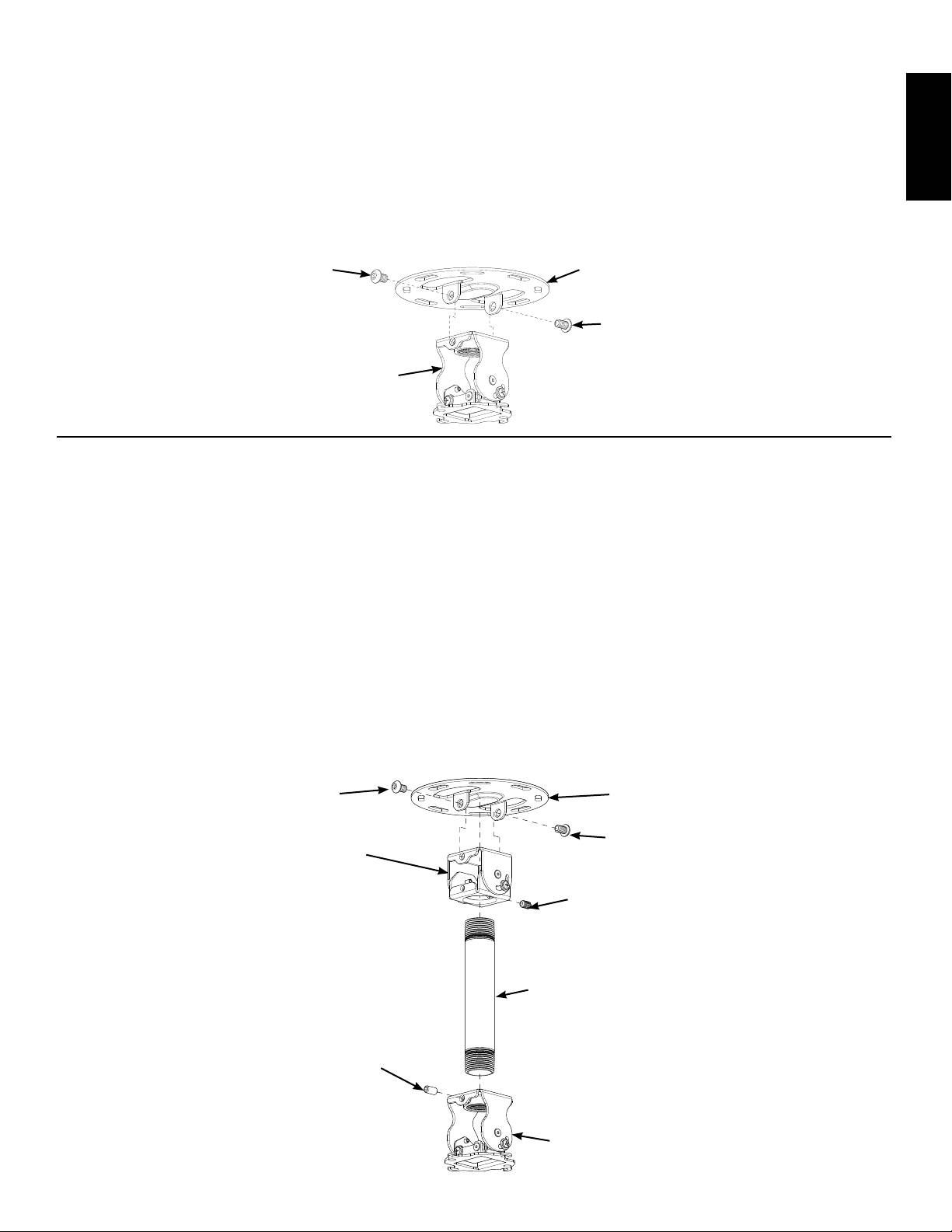
Place the Ceiling Plate (C) over the Adjustment Bracket (D), lining up the holes in both the Ceiling Plate and the Adjustment
Bracket as shown in Diagram 3A; then, using the two Cap Screws (I) secure the Adjustment Bracket to the Ceiling Plate.
Using the Allen Key (V) and the two Cap Screws (I), secure the Ceiling Plate (C) to the Adjustment Bracket (D).
Diagram 3A
I
C
I
D
Step 3B: Attach Ceiling Plate to Adjustment Bracket using Extension Pipe and NPT Adapter - Vaulted or Cathedral Ceilings
Place the Ceiling Plate (C) over the NPT Adapter (E), lining up the holes in both the Ceiling Plate and the NPT Adapter as
shown in Diagram 3B.
Using the Allen Key (V) and the two Cap Screws (I), secure the Ceiling Plate (C) to the NPT Adapter (E).
NOTE: Set Screw (J) is shorter than Set Screw (N).
NOTE: When using the NPT Extension Pipe (F), the Set Screw (N) must point either toward or away from the screen.
If a longer NPT Extension Pipe is required, custom lengths may be purchased from your local hardware store.
Thread the NPT Extension (F) into the NPT Adapter (E) and secure it with the Set Screw (J) as shown in Diagram 3B.
Thread the Adjustment Bracket (D) onto the NPT Extension (F); then, using Set Screw (N), secure the Adjustment Bracket
(D) to the NPT extension (F) as shown in Diagram 3B.
Diagram 3B
I
C
I
E
J
F
N
D
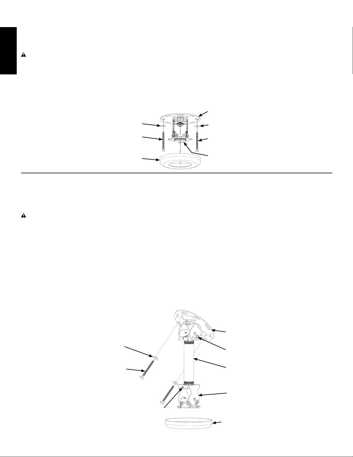
Step 4A: Attach VMPR1 Top Assembly to Ceiling and install Top Cover - Flat Ceilings
Using the Lag Bolts (U) and Lag Bolt Washers (T) secure the VMPR1 Top Assembly to the framing member at the location
selected in Step 1: Ceiling Preparation.
CAUTION: Do not over tighten the lag Bolts (U). Tighten lag Bolts until they are pulled rmly against the ceiling
Plate (C). If there is a layer of drywall or other material, this drywall or other material may not exceed 5/8 inch (15.8
ENGLISH
mm) in thickness. Failure to heed this caution may result in property damage and/or personal injury.
Tighten the Lag Bolts (U) until the Ceiling Plate (C) is ush with the ceiling drywall.
Choose the desired color Top Cover (H) and simply slide it over the Adjustment Bracket (D) until it ts snugly onto the Ceiling
Plate (C).
Diagram 4A
C
T
T
U
U
D
H
Step 4B: Attach VMPR1 Top Assembly to Ceiling and install Top Cover - Vaulted or Cathedral Ceilings
Using the Lag Bolts (U) and Lag Bolt Washers (T) secure the VMPR1 Top Assembly to the framing member at the location
selected in Step 1: Ceiling Preparation.
CAUTION: Do not over tighten the lag Bolts (U). Tighten lag Bolts until they are pulled rmly against the ceiling
Plate (C). If there is a layer of drywall or other material, this drywall or other material may not exceed 5/8 inch (15.8
mm) in thickness. Failure to heed this caution may result in property damage and/or personal injury.
Tighten the Lag Bolts (U) until the Ceiling Plate (C) is ush with the ceiling drywall.
Loosen the Pitch Adjustment Screws on the NPT Adapter (E) and set the NPT Extension Pipe (F) so that it is facing down;
then, retighten the Pitch Adjustment Screws.
Rotate the Adjustment Bracket (D) until the Set Screw (N) is facing the screen; then, tighten the Set Screw securing the
Adjustment Bracket to the NPT Extension Pipe (F).
Choose the desired color Top Cover (H) and simply slide it over the Adjustment Bracket (D) until it ts snugly onto the Ceiling
Plate (C).
Diagram 4B
C
T
E
U
F
D
N
H
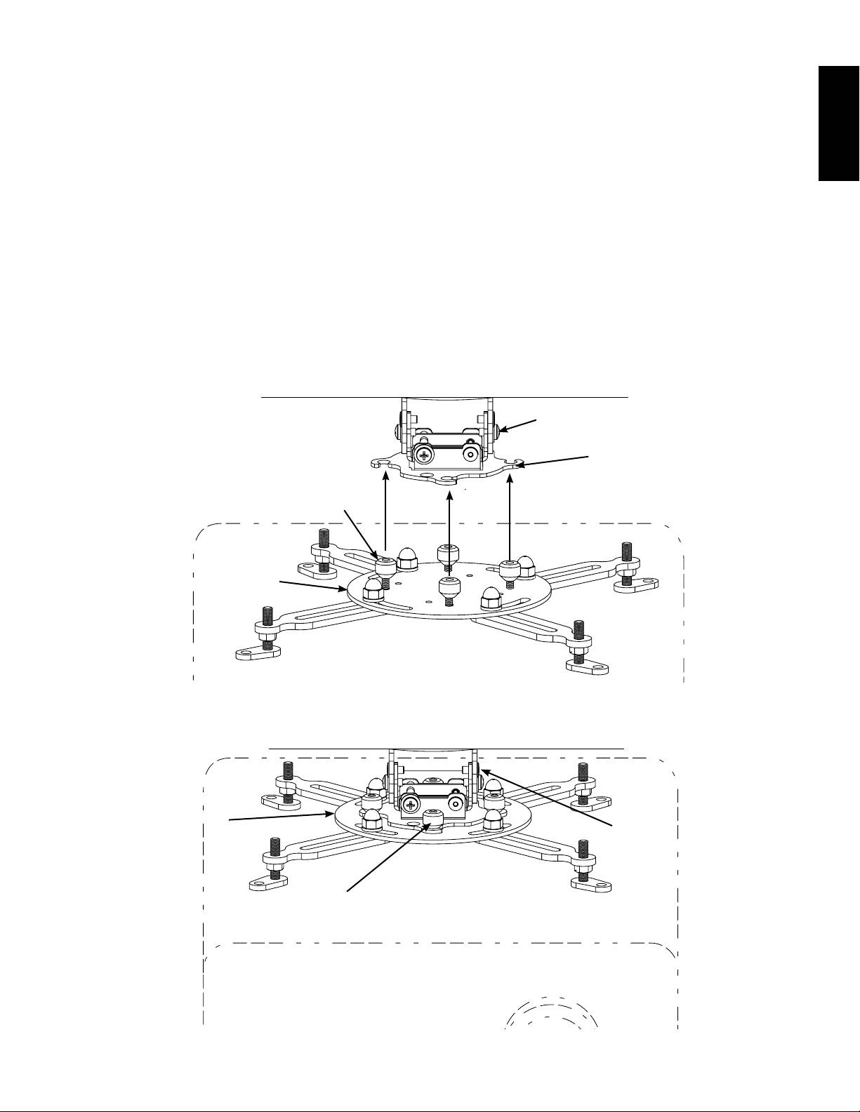
Step 5: Add Projector
ENGLISH
Once the desired position is located and all the Adjustment Screws are tightened, the projector may be removed for service
and re-installed without losing registration by reversing the following procedure.
Loosely install the Tapered Nuts (K) with the tapered end down on the Studs of the Universal Projector Interface (A) as
shown in Diagram 5A.
NOTE: The two halves of the VMPR1 attach by lifting the and rotating the Universal Projector Interface (A) so
that the Threaded Studs with Tapered Nuts (K) rotate into the Vee Slots of the Adjustment Bracket (D) as shown
in Diagram 5A. Once the desired position is located and the Tapered Nuts are tightened, the projector may be
removed for service and re-installed without losing registration by simply rotating the projector.
Align the four Vee Slots of the Adjustment Bracket (D) with the Threaded Studs and Tapered Nuts (K) of the Universal
Projector Interface (A); then, rotate the Universal Projector Interface until it is securely locked into the Vee Slots of the
Adjustment Bracket (D).
Tighten the Tapered Nuts (K), securing the projector and Universal Projector Interface (A) to the Adjustment Bracket (D) as
shown in diagram 5B.
Diagram 5A
D
Vee Slot
K
A
Diagram 5B
A
D
K
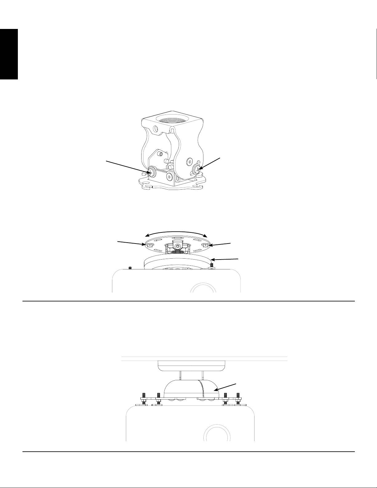
Step 6 - Projector Alignment
The VMPR1 can be adjusted for vertical elevation (Pitch), horizontal tilt (Roll), and rotation (Yaw).
Pitch Adjustment
Loosen the Pitch Adjustment Screws on both sides of the Adjustment Bracket (D) and adjust the projector to the desired
Pitch; then, retighten the Pitch Adjustment Screws as shown in Diagram 6A.
ENGLISH
Roll Adjustment
Loosen the Roll Adjustment Screws on both sides of the Adjustment Bracket (D) and adjust the projector to the desired angle
and tilt; then, retighten the Roll Adjustment Screws as shown in Diagram 6A.
Diagram 6A
Pitch Adjustment Screw
Roll Adjustment Screw
Yaw Adjustment
Lower the Top Cover (H) to expose the Lag Bolts (U). Loosen the Lag Bolts and adjust the projector to the desired angle or
yaw; then retighten the Lag Bolts and snap the Top Cover (H) back into place as shown in Diagram 6B.
Diagram 6B
Lag Bolt (U)
Lag Bolt (U)
Top Cover (H)
Step 7 - Attach Bottom cover
Flex the Bottom Cover (G) at the seam, just enough to t it around the Adjustment Bracket (D). Align the seam in the least
visible location, you may also stick a small piece of tape to the inside of the Bottom cover to secure the seam.
Diagram 7
G
Sanus Systems 2221 Hwy 36 West, Saint Paul, MN 55113 USA (6901-100023)
Customer Service: 800.359.5520. See complementary Sanus products at www.sanus.com
Оглавление
- International Assembly Instructions for model VMPR1
- Assembly Instructions for Model: VMPR1
- Instrucciones de ensamblaje del modelo: VMPR1
- Montageanleitung für Modell: VMPR1
- Instructions de montage pour le modèle : VMPR1
- Istruzioni di montaggio per il modello VMPR1
- Инструкция по сборке крепления модели VMPR1
- VMPR1 モデルの組み立て説明書
- VMPR1 型号装配说明
