Fagor 6FI-4GLSX: инструкция
Раздел: Бытовая, кухонная техника, электроника и оборудование
Тип: Варочная Панель
Характеристики, спецификации
Инструкция к Варочной Панели Fagor 6FI-4GLSX
UK
INSTRUCTIONS FOR USE AND MAINTENANCE
ES
FR
MANUEL D'INSTRUCTIONS
FR
ÈÍCTPÓÊÖÈß ÏO OÁCËÓÆÈBAHÈÞ
RU
È ÝÊCÏËÓATAÖÈÈ
PT
GB
6FI-4GLS X
6FI-4GLST X
6FID-4GL X
6FID-4GL B
6FID-4GLS X
6FID-31ML X
6FID-31MLS X

ATTENTION !
1. Read this instruction manual thoroughly before installing or using the hob.
2. This hob must be installed according to the relevant regulations and used only in well
ventilated rooms.
3. Before installing this appliance, check whether local gas supply terms (gas type and
pressure) and settings match. Hob’s settings can be found on the rating plate.
4. This hob must be connected to the internal gas network or to the liquid gas bottle and be
calibrated only by an authorised gas fitter or service engineer, which should be confirmed in
the warranty certificate. Otherwise, the warranty will be null and void.
5. The manufacturer shall be not held liable for any injuries or damages resulting from incorrect
installation or misuse of this hob.
6. This hob should only be repaired by an authorised service personnel. Repairs carried out
improperly pose a serious risk. Never use a damaged hob until it is fixed.
7. Do not carry out any repairs yourself or your warranty will be terminated.
8. This hob is a Safety Class I device and must be connected to the electrical system with an
operative external protective circuit.
9. Before installation, leave this device for 8 hours in the room where it will be installed.
10. This hob is not connected to exhaust pipes. This hob should be installed and connected
according to the valid regulations. Special attention must be paid to ventilation requirements.
Ensure that air vents are constantly opened or a forced ventilation system (cooker hood) is
installed.
11. When using this hob for a long period of time, extra ventilation may be required. This can be
done by opening windows or increasing the extractor speed (if applicable).
12. Keep packaging items away from children as they may be dangerous for them.
13. The manufacturer reserves the right to make improvements to modernize and raise the quality
of this product without prior notice. These changes will not affect operating of this hob.
14. This appliance is not intended for use by people (including children) whose physical,
sensory, or mental capacities are reduced or who lack experience or knowledge, except under
supervision or after receiving instruction regarding use of the appliance from a person
responsible for their safety. Use by children should be supervised to prevent them playing
with the appliance.
These appliances comply with following EEC Directives:
1. 73/23/EEC – Low Voltage Directive
2. 89/336/EEC – Electromagnetic Compatibility Directive
3. 90/396/EEC – Gas Appliances Directive [GAD]
UK
1

TABLE OF CONTENTS
1
OVERVIEW................................................................................................................ 3
1.1 HOB APPLICATION....................................................................................................................................3
1.2 TECHNICAL DATA......................................................................................................................................3
1.3 HOB MODELS.............................................................................................................................................3
1.4 SAFETY GUIDELINES................................................................................................................................4
1.5 PREPARATION...........................................................................................................................................5
2 INSTALLATION......................................................................................................... 5
2.1 GENERAL NOTES......................................................................................................................................5
2.2 GAS HOB INSTALLATION .........................................................................................................................6
2.3 CONNECTING THE HOB TO THE NATURAL GAS SUPPLY...................................................................7
2.4 CONNECTING THE HOB TO THE LIQUID GAS BOTTLE........................................................................7
2.5 NOZZLE REPLACEMENT..........................................................................................................................8
2.6 ADJUSTING CONTROL KNOBS................................................................................................................8
2.7 CONNECTING THE HOB TO THE MAINS ................................................................................................9
3 OPERATION.............................................................................................................. 9
3.1 GAS BURNERS ..........................................................................................................................................9
3.1.1 Flame adjusting.....................................................................................................................................10
3.1.2 Igniting burners .....................................................................................................................................10
3.1.3 Turning off burnerS...............................................................................................................................11
3.1.4 Operating the hob supplied with liquid gas from bottle.........................................................................11
3.1.5 Vessel selection....................................................................................................................................11
3.2 OPERATING THE HOT PLATE................................................................................................................12
3.2.1 Operating hints......................................................................................................................................12
3.2.2 Control knob of the electric plate ..........................................................................................................12
3.2.3 Vessel selection....................................................................................................................................13
4 CLEANING AND MAINTENANCE ............................................................................ 14
4.1 GENERAL RECOMMENDATIONS...........................................................................................................14
4.2 CLEANING THE HOB AND BURNERS....................................................................................................14
5 ABNORMAL HOB OPERATION ............................................................................... 15
2
UK
OVERVIEW
1 OVERVIEW
1.1 HOB APPLICATION
This gas-electric hob is intended for domestic cooking only. It must not be used for any other purpose.
1.2 TECHNICAL DATA
Table 1
6FI-4GLSX
6FID-4GLX
6FID-4GLB
6FID-4GLSX
6FID-31MLX
6FI-4GLSTX
6FID-31MLSX
Overall
Total height 90
dimensions
Width 590
[mm]
Depth 523
Rated supply voltage 230V ~ 50Hz
AUX burner 1,0 kW
Gas
SR burner 1.75 kW
burners
R burner 3,0 kW
TC burner 3.8 kW
Electric hot plate 145mm / 1,5 kW
Burners’ igniters
Flame failure protection
Plates HOBS are made in different colours. The following letter symbols are used for different colours: X – inox;
B – white; A – anthracite.
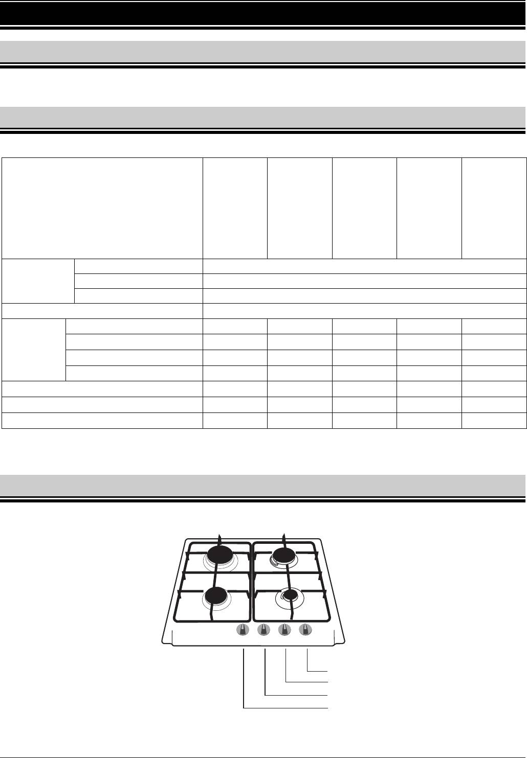
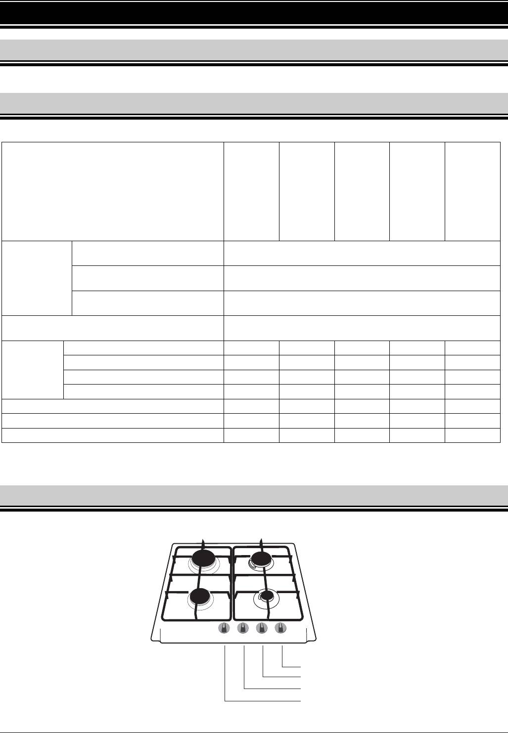
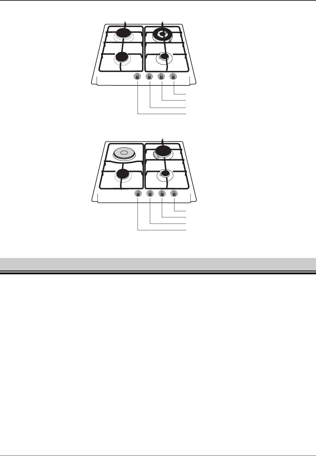
1.3 HOB MODELS
6FI-4GLSX; 6FID-4GLSX; 6FID-4GLX; 6FID-4GLB;
Rapid burner R
Semi-rapid burner SR
3,0 kW
1,75 kW
Semi-rapid burner SR
Auxiliary burner AUX
1,75 kW
1,0 kW
Control knob for SR burner
Control knob for AUX burner
Control knob for SR burner
Control knob for R burner
Fig. 1
UK
3
OVERVIEW
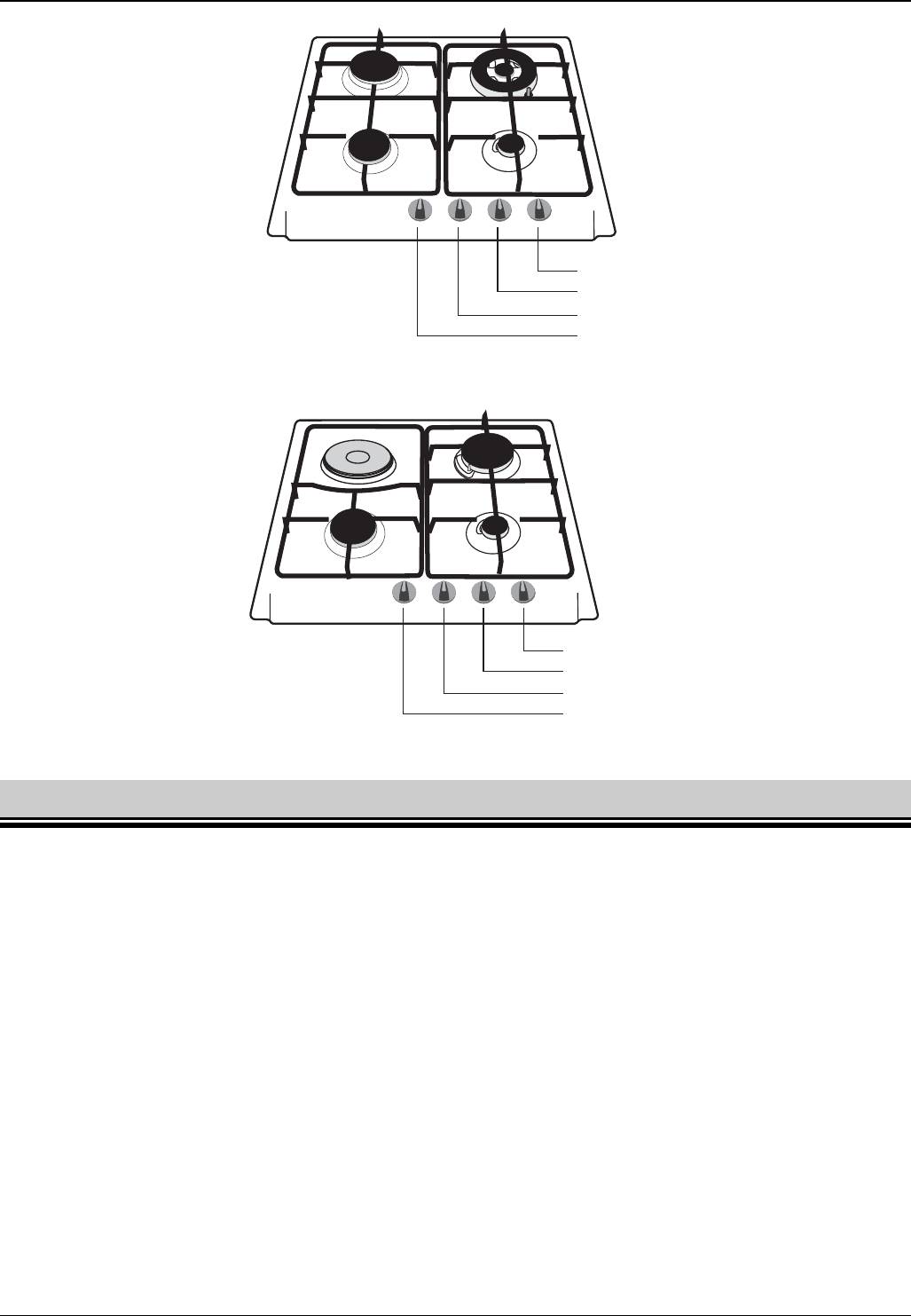
6FI-4GLSTX;
Rapid burner R
Triple-crown burner TC
3,0 kW
3,8 kW
Auxiliary burner AUX
Semi-rapid burner SR
1,0 kW
1,75 kW
Control knob for TC burner
Control knob for AUX burner
Control knob for R burner
Control knob for SR burner
Fig. 2
6FID-31MLX;6FID-31MLSX
Great burner R
Electric plate
3,0 kW
1,5 kW
Auxiliary burner AUX
Semi-rapid burner SR
1,0 kW
1,75 kW
Control knob for R burner
Control knob for AUX burner
Control knob for SR burner
Control knob for the electric plate
Fig. 3
1.4 SAFETY GUIDELINES
The gas burners, electric plate HOT PLATE, grates, pots and pans become hot when hob is in use.
Handle with care to avoid burns. Pay special attention to children.
When using the drawer under the hob, do not keep flammable or hot-sensitive objects in it.
All electric cords of domestic appliances near the operating hob should be kept away from the hot
burners and electric plate.
Use protective gloves when removing hot pots and pans from the hob.
Keep flammable objects away from burners.
Do not put deformed or unstable pots and pans on grates as they can overturn and flood burners.
Do not put empty pots and pans on the operating burner or electric plate.
Reduce or turn off the flame before removing pots and pans from burners.
While in use, the hob must not be left unattended. Never leave the operating device unattended
especially when frying as overheated oil or fat may ignite.
When in use, the hob will produce heat and moisture in the room in which it has been installed.
Ensure that the room is properly ventilated. Natural ventilation openings should be opened or a
mechanical ventilation device (cooker hood with extractor) should be installed.
Never use the hob to heat a room.
It is strictly forbidden to modify the hob so that it can use another type of gas or to make changes in
the electrical or gas system of the appliance
4
UK
INSTALLATION
In case of a gas leakage:
immediately close the valve of the gas system or gas bottle
ventilate the room thoroughly
call gas service
During this time do not:
light matches or smoke
turn on or turn off electrical devices (radio, door bell, light) or mechanical devices that
spark.
If the gas coming out of a leaky valve of the gas bottle will ignite, put a wet blanket on the
bottle to cool it and then close the valve.
DO NOT USE A DAMAGED GAS BOTTLE!
Never use the hob if its supply wire or plug is broken.
Warning !
Should you find any crack on the electric plate, immediately disconnect the hob
from the electric system and call an authorised service personnel.
1.5 PREPARATION
1. Remove all packaging items, including protective layers, from chromed elements and stainless steel
parts.
2. Wipe enamelled surfaces with a soft, damped cloth.
3. Make sure that all parts of burners are positioned correctly.
4. Before the first use, turn the electric plate ON for approx. 5 minutes by turning the knob to position
"6", exceptionally without any pot or pan. During this time the protective layer on the plate will burn
out. When the plate has cooled down, wipe the plate with a dry cloth.
2 INSTALLATION
2.1 GENERAL NOTES
Attention !
1. This hob must be installed and repaired only by an authorised fitter according to
the manufacturer’s instructions.
2. Before installation, disconnect the hob from the electric supply.
After unpacking, make sure that the hob has no visible damage and the power cord is in good
condition. If there is a damage, please contact our Customer Service.
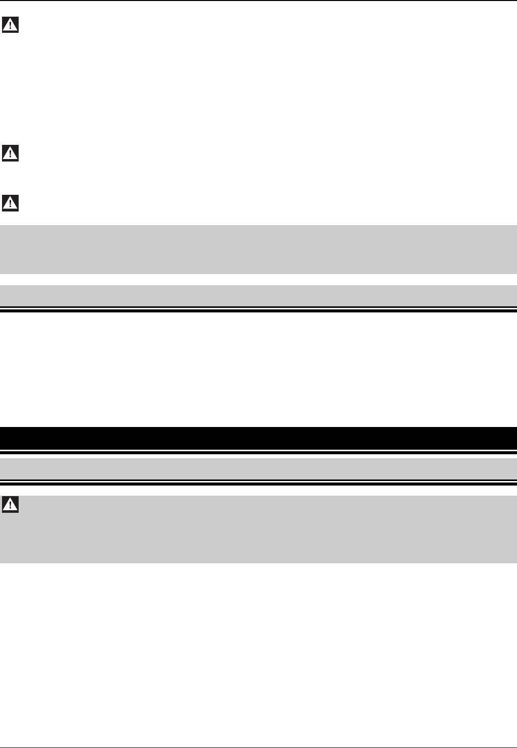
This hob may be installed on a worktop that is at least 30mm thick (Fig. 5). The worktop must be
heat-resistant.
The wall next to the rear side of the hob should be made of incombustible material.
A minimum distance of 100mm must be maintained between the side edges of the hob and any
adjacent furniture.
To reduce negative impact of draught on burner operation, do not install this hob on the window-door
line.
There should be a free space left over the hob for discharging fumes. The best solution is to install a
cooker hood which will absorb and discharge these fumes. The minimum distance between the hob
and cooker hood is 650mm.
UK
5
INSTALLATION
There must not be any cabinet fitted right above the hob.
In case of mounting a horizontal partition "A" under the hob, leave the distance at least 150mm
between the hob and the partition (Fig. 6).
Fig. 5 Fig. 6
2.2 GAS HOB INSTALLATION
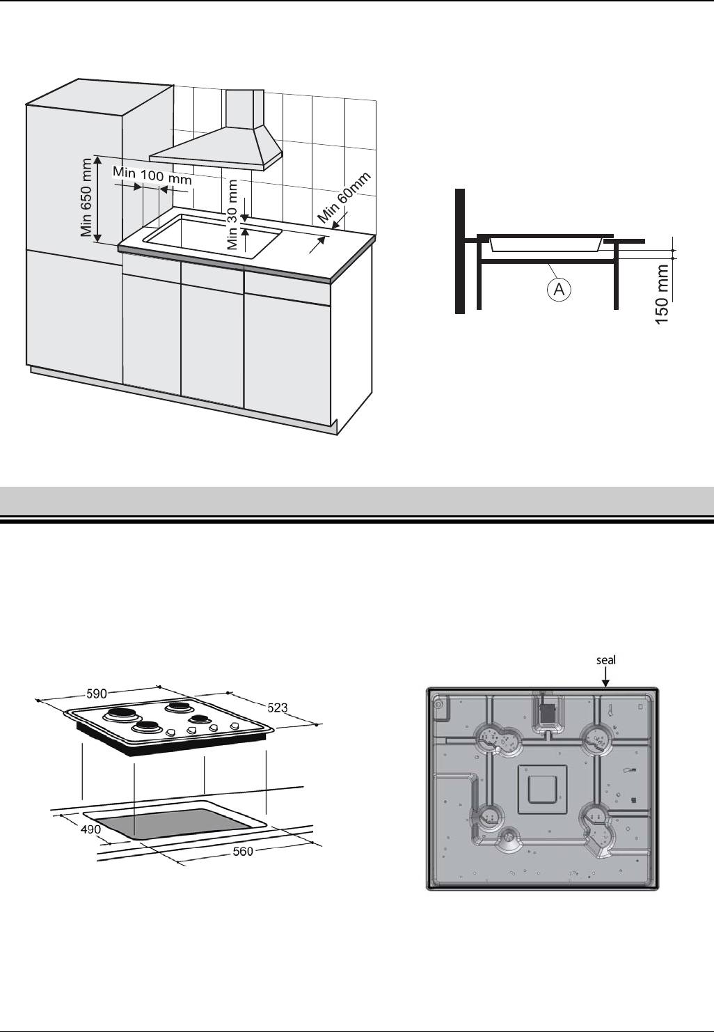
1. Make the 490 x 560 [mm] rectangular cut-out in the worktop. The dimensions of the cut-out can be
found in Fig. 7.
2. The hob is equipped with a seal with tape-protected adhesive surface. Remove the tape from the
seal.
3. Turn the hob upside down and stick the seal around the internal edge (Fig. 8).
Fig. 7 Fig. 8
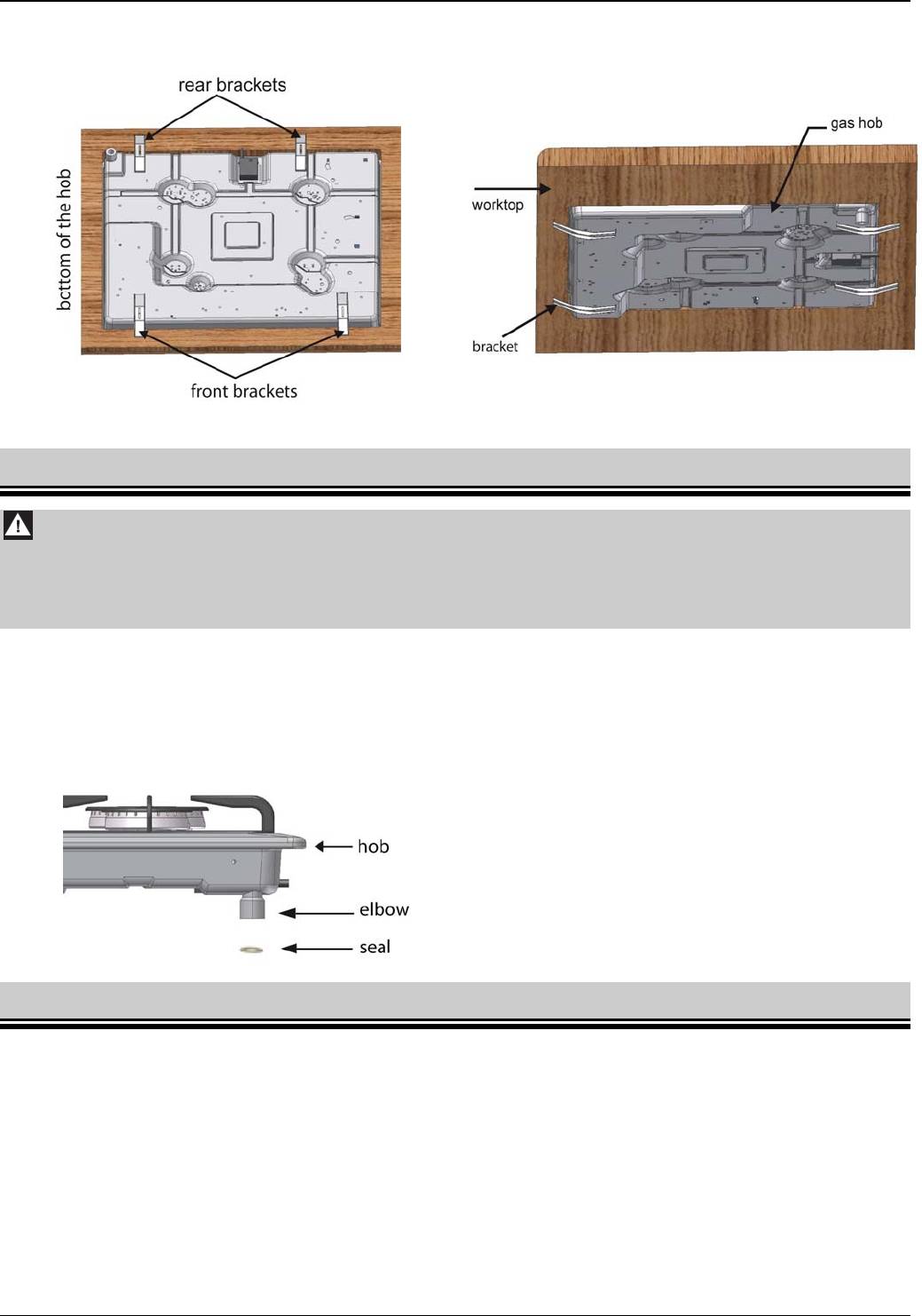
4. Place the hob in the middle of the cut-out and push it so that the seal adheres tight to the worktop.
5. Fix the hob with the four brackets which are included together with other connecting parts (Fig. 9 and
10).
6
UK
INSTALLATION
6. After installing the hob, the horizontal partition "A" may be placed under the worktop which will
protect the user against accidental touching of a hot hob from the bottom.
Fig. 9 Fig. 10
2.3 CONNECTING THE HOB TO THE NATURAL GAS SUPPLY
Attention !
1. The hob must be connected to the gas system according to relevant regulations
and by an authorised gas fitter.
2. Before installation, make sure that the shut-off cock is closed.
This hob is designed for gas and pressure indicated on the rating plate. The hob is equipped with an
elbow and seal (Fig. 11).
Connection to the internal gas system should be either rigid or with a flexible metal pipe.
Gas supply is ended with a shut-off cock. The shut-off cock should be easily accessible after
installing the hob in the worktop.
Fig. 11
2.4 CONNECTING THE HOB TO THE LIQUID GAS BOTTLE
The hob may be converted for use with liquid gas. For this purpose nozzles in burners have to be
replaced and knobs have to be adjusted.
If this hob is intended for use with gas bottles, it should not be installed in a cellar or any other
compartment with a floor below ground level as the liquid gas is heavier than air and accumulates at
the floor level.
When connecting the hob to the gas bottle, use a certified rubber hose.
Each time the gas bottle is connected, check the tightness of the valve on the gas bottle and the
connection and operation of the reducer.
UK
7
INSTALLATION
ATTENTION !
1. Checking the leakage with an open flame (e.g. with a match or a candle) is
unacceptable. It may lead to an explosion !
2. Check condition of the hose and connection tightness regularly, according to the
valid regulations.
2.5 NOZZLE REPLACEMENT
ATTENTION !
Before nozzle replacement and adjustments, disconnect the hob from the mains.
Nozzle diameters for particular gas type are shown in Table 2.
Table 2
AUX burner SR burner R burner TC burner
G 20 20 mbar
X072 Z097 Y118 K1,35
G 30/31 29/37 mbar
050 065 085 098
The hob is adjusted to the type of gas and pressure stated on the appliance's rating plate.
In the event of a change of the type of gas replace the nozzles and adjust the taps.
Before beginning these activities you must:
– shut down the cock shutting off the gas supply system or cylinder from the hob,-shut
down all the taps in the hob,
–
disconnect the hob from the mains.
Then:
– remove the burners' lids and rings,
–
remove the nozzles with socket wrench no. 7 and replace them with new ones in
accordance with table2,
–
put burners' rings and lids back,-
adjust the taps and check the connections for soundness
Fig. 12
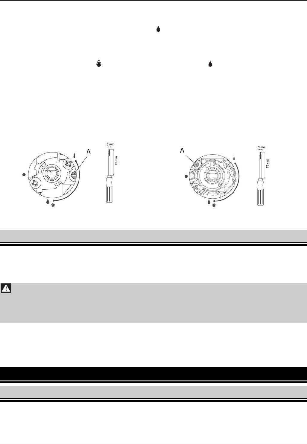
2.6 ADJUSTING CONTROL KNOBS
ADJUSTING THE TAPS
The adjustment of a gas tap consists in setting the burner flame in the simmering position. To
adjust the taps remove all the knobs and control panel.
8
UK
OPERATION
Then:
– open the gas flow with a knob and light the adjusted burner,
– set the knob in the simmering position . and then, without changing that position,
remove it from the tap's mandrel
turn the adjusting screw "A" (Fig. 13) and observe the flame; set such a height of a flame
so as it will not be extinguished by a small draught and while quickly turning the knob
from full flame position to the economical flame position and vice versa
a knob is properly adjusted when the flame cone is green-blue and its height is about 2-
4mm;
if there are significant pressure changes in the gas supply system (flame height changes
in a full flow setting), the economical flame should be set with the low gas pressure in
such a way that it will not be extinguished during normal operation
after adjustment, put on the knob and turn off the flame.
Knob without protection Knob with protection
Fig.13
2.7 CONNECTING THE HOB TO THE MAINS
The hob is equipped with a cord without a plug. Before connecting the hob to the mains make sure that:
mains voltage complies with data found on the rating plate,
power of the electric system is sufficient when compared with the power consumption of the
hob.
Attention !
1. The plug should be installed by a qualified authorised fitter.
2. The hob socket must be easily accessible for the user.
3. Ensure that the supply cord does not come into contact with hot parts of the hob.
The hob should be connected to the socket with a properly connected protecting terminal. Connecting
the hob to the socket without a protecting contact creates a risk of electric shock in case of a failure of
the electric system.
If the supply cord is damaged, it must be replaced. Contact the manufacturer, a service workshop or a
qualified person to avoid danger.
3 OPERATION
3.1 GAS BURNERS
Never take off the grates or place pots and pans directly on burners.
Prevent pots and pans boiling over and flooding burners.
Before opening a gas system or gas bottle valve make sure that all control knobs are closed.
UK
9
OPERATION
For the proper operation ensure that burners and igniters are clean and dry.
If the hob is equipped with a flame failure protection after igniting the burner keep the control
knob fully pushed for a while to activate the protection.
Do not overload the grates.
Never touch hot burners, graters, pots and pans.
To obtain proper and economical burners operation make sure that:
flame height is adequate,
pots and pans are properly selected.
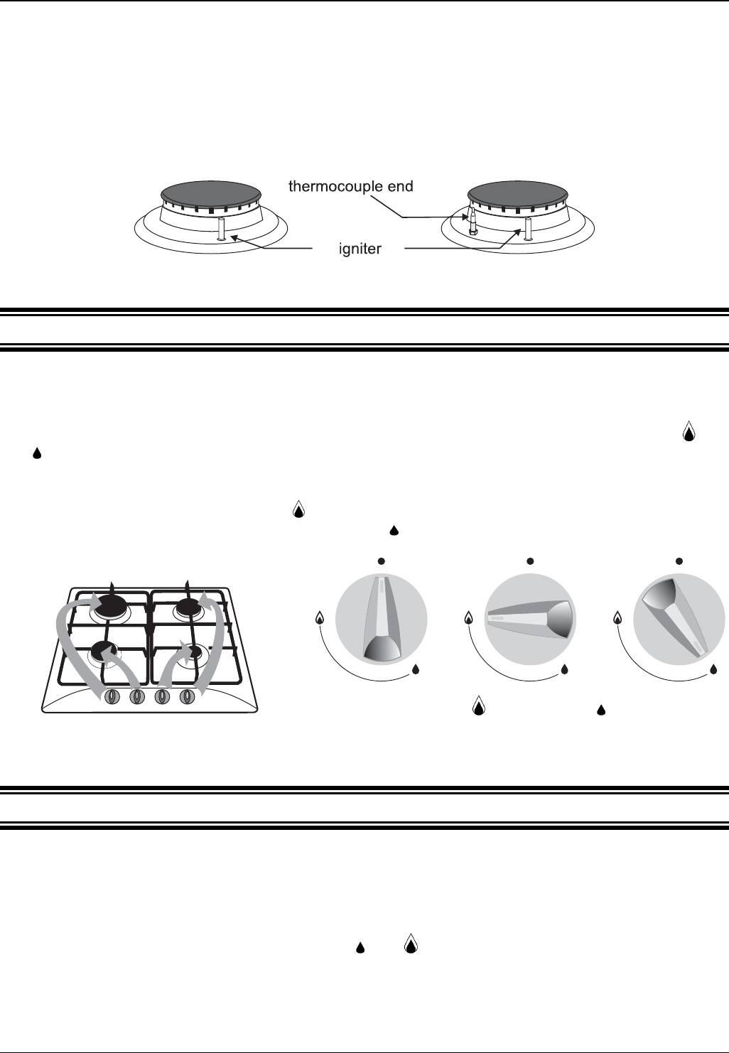
Burner without
Burner with
flame failure
flame failure
protection
protection
Fig. 14
3.1.1 FLAME ADJUSTING
Gas flow in individual burners is opened and closed using control knobs.
Before igniting the burner make sure that the corresponding control knob is to be operated.
Corresponding burners and control knobs are shown in Fig. 15.
Flame height depends on the control knob position (Fig. 16). Adjust the flame only between and
.
Flame should not spread beyond the bottom of the vessel but spread on 2/3 of the vessel’s bottom.
This will ensure gas efficiency and the flame will not singe pots and pans.
When the control knob is in position the flame is high. High flame should be used until a liquid
starts boiling and then turn down the flame to small
(economical) for further cooking.
0 – burner turned off;
– high flame; – small flame
(economical)
Fig. 15 Fig. 16
3.1.2 IGNITING BURNERS
Hobs: 6FID-31MLX; 6FID-4GLX; 6FID-4GLB
push the knob of a burner until it stops, then turn it anticlockwise and push down until the burner
ignites
after ignition release the knob
adjust to the desired flame height between
and
Hobs: 6FI-4GLSX; 6FID-4GLSX; 6FI-4GLSTX;6FID-31MLSX
push the knob of a burner until it stops, then turn it anticlockwise and push down until the burner
ignites, do not release the knob for another 5 seconds in order to activate flame failure
protection
10
UK
OPERATION
if the flame goes out, repeat these steps keeping the knob pushed for 5 seconds longer
adjust to the desired flame height between
and
3.1.3 TURNING OFF BURNERS
Turn the control knob clockwise to the zero position marked "".
3.1.4 OPERATING THE HOB SUPPLIED WITH LIQUID GAS FROM BOTTLE
Before igniting the first burner, open the gas bottle valve and then ignite burners as described above.
When closing gas supply before turning off the last burner:
close the gas bottle valve
after the flame is extinguished close the relevant control knob
The gas bottle valve should be closed when the hob is not used.
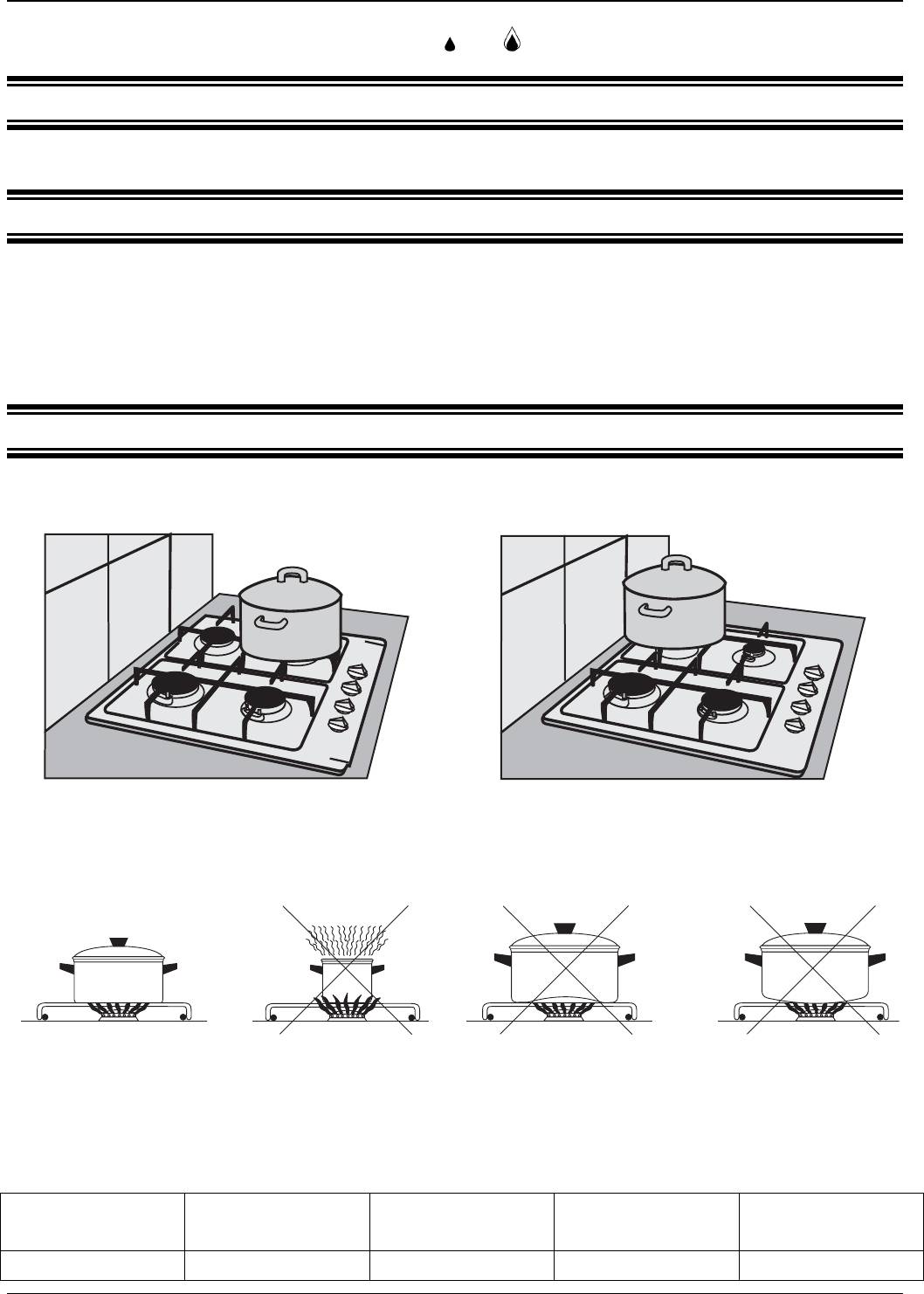
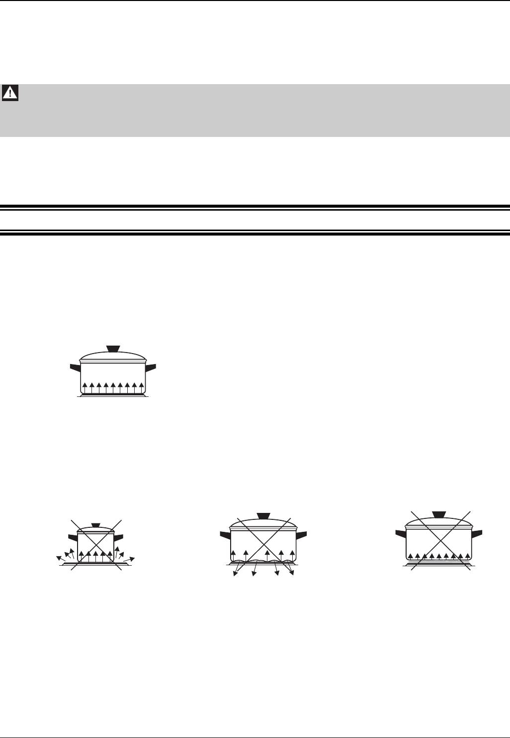
3.1.5 VESSEL SELECTION
Pots should not be too high. It is recommended to use vessels whose height is about 2/3 of their
bottom diameter.
Fig. 17 Fig. 18
Do not place large pots in the front part of the
Do not place large pots in the rear part of the
hob as the burner flame may overheat knobs.
hob as the flame may overheat the wall.
Adequate vessel
Vessel too small in
Concave bottom Convex bottom
relation to burner
size
Fig. 19
Recommended vessels diameters for particular burners:
Triple-crown
Great
Rapid
Semi-rapid
Auxiliary
Burner TC
Burner GR
Burner R
Burner SR
Burner AUX
23 – 30 cm 18 – 28 cm 16 – 26 cm 14 – 22 cm 12 – 16 cm
UK
11
OPERATION
3.2 OPERATING THE HOT PLATE
3.2.1 OPERATING HINTS
Keep the plate clean. Dirty plate does not transfer all power.
Except first use, turn on the plate only after putting a pot on it.
Never put wet vessels on the plate as moisture causes corrosion.
Never sprinkle a hot plate with cold water.
Switch the plate off a few minutes before finishing the cooking as the plate accumulates heat and
remains hot for some time after switching it off.
Do not use the plate to prepare food wrapped in aluminium foil or in plastic containers. Do not put
plastic plates or other objects on the plate.
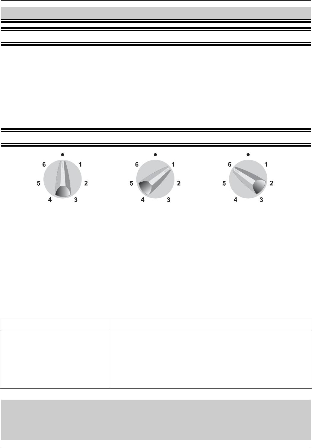
3.2.2 CONTROL KNOB OF THE ELECTRIC PLATE
Plate turned off Minimum heating power Maximum heating power
Fig. 20
Heating power is adjusted using the 7-position control knob. Power changes in steps. Such controls
ensure proper and economical adjustment of the plate heating power.
A control knob may be turned in both directions. Digits 1 to 6 indicate control knob positions (Fig.
20). These positions correspond to certain heating power.
Using the 7-positon control knob
Knob setting Suitable for
6
rapid cooking or intensive frying
5
intensive roasting of meat, fish
4
mild roasting
3
further cooking huge volumes of dish, thick soups
2
cooking potatoes, soups
1
simmering vegetables, fish in its own juice
0
plate turned off
Important !
1. Except the first use, do not turn on the hot plate before putting a pot on it.
2. Put a thin layer of protective agent on the plate, if it will not be used for a longer
time.
12
UK
OPERATION
Cooking Roasting
Turn the knob to position 6 and wait till the
Turn the knob to position 6 and heat the oil.
liquid starts boiling and turn to position 2 for
Then put ingredients into vessel and turn the
further cooking. Adjust heating power
knob to position 4. Adjust heating power
accordingly.
accordingly.
ATTENTION !
After switching off the plate remains hot for some time. Do not touch the plate or
place any vessels or objects on it. Pay special attention to children.
It is recommended to switch the electric plate off for 5 to 10 minutes before finishing boiling to make
full use of its final power.
Do not put unused vessels on the electrical plate.
3.2.3 VESSEL SELECTION
Pots and pans put on the electrical plate should have thick flat and dry bottoms with a diameter equal
or slightly larger than the plate diameter. Large amount of heat is wasted if the vessel bottom has a
smaller diameter.
Uneven bottoms extend boiling time and raise power consumption.
Vessel should be covered to prevent accumulating too much fumes in the kitchen.
Correct !
Low power consumption
Good heat conducting
Fig. 21
even bottom of the vessel
bottom diameter is the same as plate diameter
cover tightly adheres to the vessel
Incorrect !
High power consumption
Poor heat conducting
Long cooking time
Vessel too small Uneven vessel bottom Dirty plate surface
Fig. 22
UK
13
CLEANING AND MAINTENANCE
4 CLEANING AND MAINTENANCE
Attention !
Before cleaning, you must disconnect the hob’s plug from the socket and turn off all
burners.
4.1 GENERAL RECOMMENDATIONS
Appliance must be regularly cleaned in order to maintain proper technical condition and good
appearance.
Never clean the hob with coarse agents which scratch surfaces, sharp tools, wire sponges or
aggressive chemical agents.
Clean the control panel and knobs with mild cleaning fluids without abrasives to prevent damaging
overprints.
For the proper hob operation, ensure that burner elements and igniters are clean and dry.
Soak dirty grates in warm water with detergent, then wash and dry the grates.
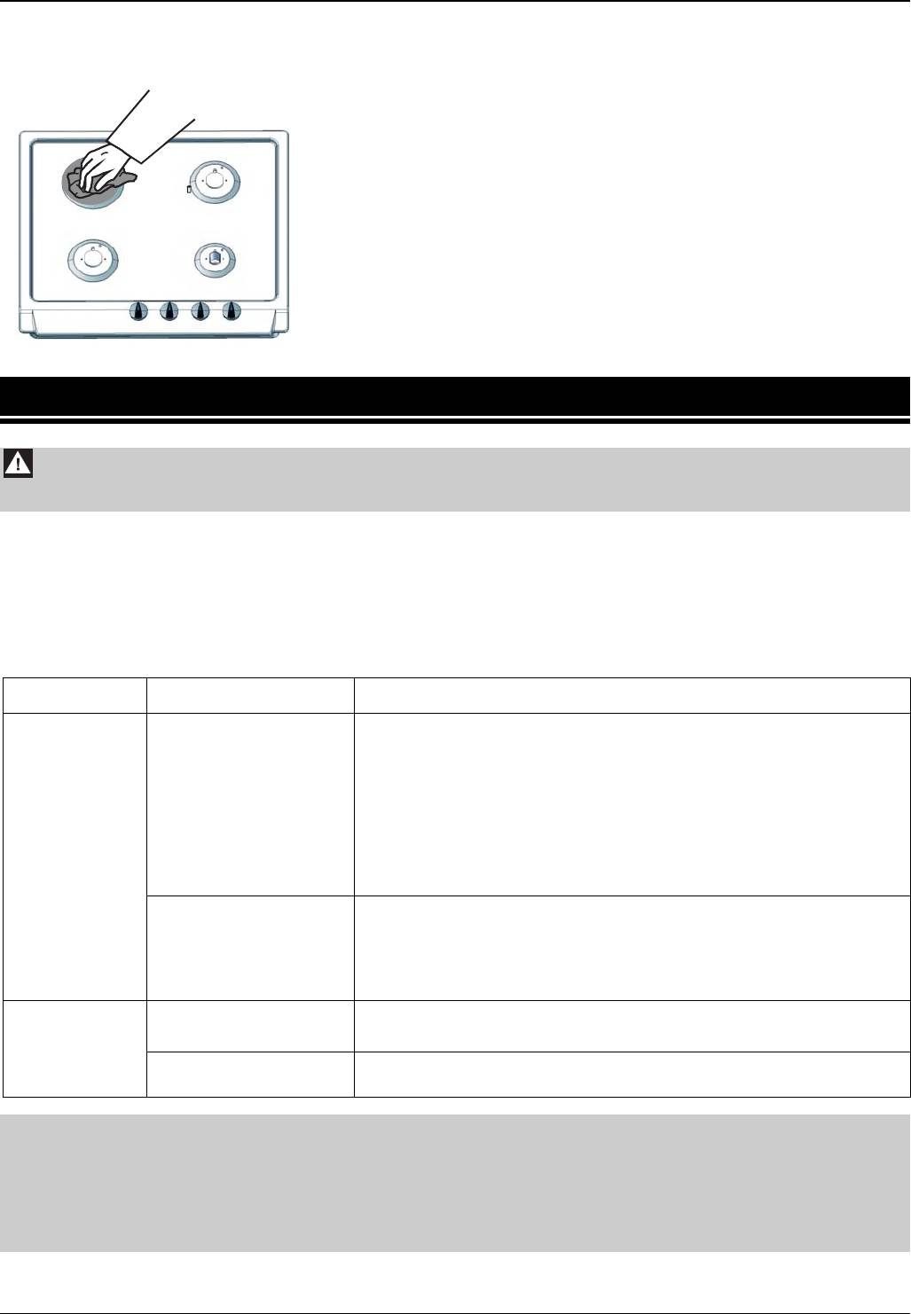
4.2 CLEANING THE HOB AND BURNERS
Before cleaning the hob remove the grates and burner
caps and crowns.
Wipe the enamelled surface of the hot plate using a soft
cloth or sponge moistened with a solution of hot water
and mild detergent.
The hob surface around burners should be always kept
clean. It is very important because during normal hob
operation contaminations accumulating in the gap
between burner crown and the hob impair the gas
Fig. 23
mixture burning.
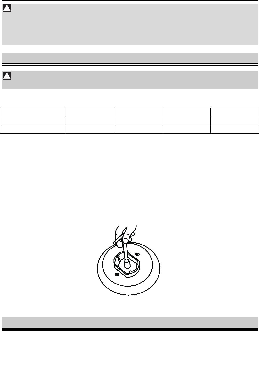
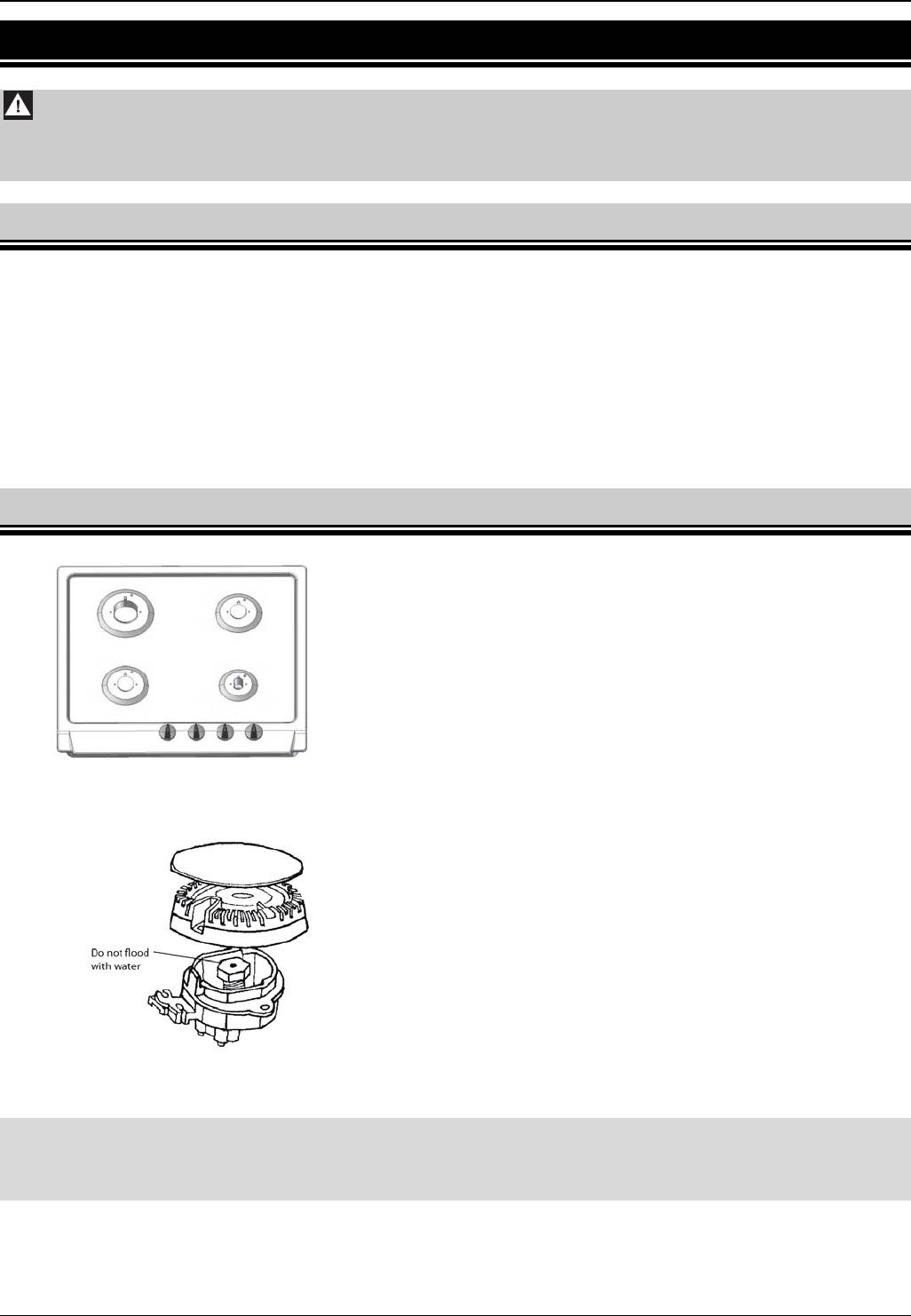
During cleaning the hob, avoid excess water to prevent
it from getting into the hob recess and flooding the
nozzles (Fig. 24). If the nozzle is flooded, the burner will
not ignite.
The nozzle should always be clean. A dirty nozzle may
clog and the flame will be low or the burner will not ignite
at all. Clean the nozzle with a brush moistened with
solvent.
Fig. 24
ATTENTION !
Burners, igniters and thermocouple ends should be cleaned after each flooding.
Blooms and contaminations must be removed regularly.
To clean the burner, remove its cap and crown (Fig. 12), soak them in warm water with detergent
and wash each part separately.
Use a sponge or a brush to wash burner parts and a steel wire to unblock flame openings. After
cleaning, make sure that the flame openings are not clogged.
14
UK
ABNORMAL HOB OPERATION
Cleaned burner parts should be thoroughly dried because if they are wet the gas will not burn or will
burn improperly. After drying, re-install the burner elements in the order reverse to that used during
their removal and do not damage igniters and thermocouple ends.Cleaning the electric plate
Clean the plate with a soft cloth or a sponge. Nickel
plated finishing rings should be washed with mild
cleaning agents. After cleaning preserve the plate
with white mineral or silicone oil. Do not use
vegetable or animal oils for preserving the plate.
Fig. 25
5 ABNORMAL HOB OPERATION
Attention !
Before troubleshooting disconnect the hob plug from the electric socket.
Failures can occur during the hob operation. Some minor faults may be remedied by the user
according to directions in Table 3.
During the warranty period, all repairs except those specified below should be carried out by an
authorised service workshop.
After the warranty period, a user should have the appliance inspected by a service shop regularly.
Table 3
Symptoms
Causes Troubleshooting
Close all control knobs
Close shut-off cock
Clogged flame
Ventilate the room
openings in the
Remove and clean burner parts making sure that flame
burner.
openings are not clogged
Burner will not
Install all burner parts properly and try to ignite the burner
ignite
again
Remove all burner parts
Clogged (flooded)
Clean and dry the hob recess of the relevant nozzle
nozzle
Clean the nozzle and unblock it with thin copper wire if
necessary (never use the steel wire or enlarge the opening)
The igniter
Open circuit in
Check the fuse in a house electric system and replace if
will not ignite
electric system
burnt out
gas (no
Contaminated
Clean and thoroughly dry burners and igniters
spark)
burners or igniters
Attention !
1. If after following the steps above the hob does not operate normally, contact the
nearest authorised service workshop. Never use a faulty hob before it is repaired.
2. If the hob is not going to be used for a longer period of time, clean it thoroughly,
close the shut-off valve and unplug the hob from mains.
UK
15

ATTENTION !
1. Lisez entièrement ce manuel d'instructions avant d'installer ou d'utiliser la table de cuisson.
2. Cette table de cuisson doit être installée conformément aux réglementations en vigueur et
utilisée uniquement dans des pièces correctement ventilées.
3. Avant d'installer cet appareil, assurez-vous que les conditions locales en termes
d'alimentation en gaz (type de gaz et pression) correspondent aux paramètres de la table de
cuisson. Les paramètres de la table de cuisson se trouvent sur la plaque signalétique.
4. Cette table de cuisson doit être connectée au réseau de gaz interne ou à une bouteille de gaz
liquide et doit être réglée par un monteur d'installations au gaz ou un dépanneur agréé, le
certificat de garantie faisant preuve. Le cas contraire entraînerait l'annulation de la garantie.
5. Le fabricant ne saurait être tenu pour responsable d'aucun dommage corporel ou matériel
dus à une installation ou une utilisation incorrectes de cette table de cuisson.
6. Cette table de cuisson ne doit être réparée que par un personnel de maintenance agréé. Des
réparations effectuées de manière incorrecte peuvent entraîner des risques importants.
N'utilisez jamais une table de cuisson endommagée avant qu'elle ne soit réparée.
7. N'effectuez jamais les réparations par vous-même, sans quoi la garantie serait définitivement
annulée.
8. Cette table de cuisson est un appareil de classe de sécurité I ; elle doit être connectée au
système électrique à l'aide d'un circuit de protection externe opérationnel.
9. Avant de procéder à l'installation, laissez cet appareil reposer pendant 8 heures dans la pièce
où il sera installé.
10. Cette table de cuisson n'est connectée à aucune conduite d'évacuation. Cette table de
cuisson doit être installée et connectée conformément aux réglementations en vigueur. Une
attention toute particulière doit être portée aux conditions de ventilation. Assurez-vous de
l'ouverture permanente de grilles d'aération ou de la présence d'un système de ventilation
(hotte d'aspiration).
11. Lorsque vous utilisez cette table de cuisson pendant une durée prolongée, une ventilation
supplémentaire peut s'avérer nécessaire. Vous pouvez à cette fin ouvrir une fenêtre ou
accroître la vitesse de l'extracteur (le cas échéant).
12. Conservez les éléments d'emballage hors de portée des enfants afin de ne pas les exposer au
moindre danger.
13. Le fabricant se réserve le droit d'apporter des modifications à ce produit afin d'en améliorer la
qualité ou de le moderniser, sans préavis. Ces modifications n'altéreront pas le
fonctionnement de cette table de cuisson.
Ces appareils sont conformes aux directives CEE suivantes :
73/23/CEE – Directive Basse tension
89/336/CEE – Directive Compatibilité électromagnétique
90/396/CEE – Directive relative aux appareils à gaz
1
FR

SOMMAIRE
1
PRESENTATION ....................................................................................................... 3
1.1 CHAMP D'APPLICATION DE LA TABLE DE CUISSON............................................................................3
1.2 DONNEES TECHNIQUES..........................................................................................................................3
1.3 MODELES DE TABLES DE CUISSON ......................................................................................................3
1.4 DIRECTIVES DE SECURITE......................................................................................................................4
1.5 PREPARATION...........................................................................................................................................5
2 INSTALLATION......................................................................................................... 5
2.1 REMARQUES D'ORDRE GENERAL..........................................................................................................5
2.2 INSTALLATION DE LA TABLE DE CUISSON AU GAZ.............................................................................6
2.3 RACCORDEMENT DE LA TABLE DE CUISSON AU GAZ NATUREL......................................................7
2.4 RACCORDEMENT DE LA TABLE DE CUISSON A UNE BONBONNE DE GAZ LIQUIDE ......................8
2.5 REMPLACEMENT DES BUSES.................................................................................................................8
2.6 REGLAGE DES BOUTONS DE COMMANDE...........................................................................................9
2.7 RACCORDEMENT DE LA TABLE DE CUISSON AU RESEAU ELECTRIQUE........................................9
3 UTILISATION.......................................................................................................... 10
3.1 BRULEURS A GAZ...................................................................................................................................10
3.1.1 Réglage de la flamme...........................................................................................................................10
3.1.2 Allumage des brûleurs ..........................................................................................................................11
3.1.3 Extinction des brûleurs..........................................................................................................................11
3.1.4 Utilisation de la table de cuisson alimentée par une bonbonne de gaz liquide....................................11
3.1.5 Sélection des récipients........................................................................................................................12
3.2 UTILISATION DE LA PLAQUE CHAUFFANTE........................................................................................12
3.2.1 Conseils d'utilisation..............................................................................................................................12
3.2.2 Bouton de commande de la plaque électrique .....................................................................................13
3.2.3 Sélection des récipients........................................................................................................................14
4 NETTOYAGE ET ENTRETIEN ................................................................................. 14
4.1 RECOMMANDATIONS D'ORDRE GENERAL .........................................................................................14
4.2 NETTOYAGE DE LA TABLE DE CUISSON ET DES BRULEURS..........................................................15
4.3 NETTOYAGE DE LA PLAQUE ELECTRIQUE.........................................................................................16
5 FONCTIONNEMENT ANORMAL DE LA TABLE DE CUISSON ................................. 16
FR
2
PRESENTATION
1 PRESENTATION
1.1 CHAMP D'APPLICATION DE LA TABLE DE CUISSON
Cette table de cuisson au gaz et à l'électricité est destinée à un usage domestique uniquement. Elle ne
doit être utilisée à aucune autre fin.
1.2 DONNEES TECHNIQUES
Tableau 1
6FI-4GLSX
6FID-4GLX
6FID-4GLB
6FID-4GLSX
6FID-31MLX
6FI-4GLSTX
6FID-31MLSX
Hauteur totale 90
Dimensions
générales
Largeur 590
[mm]
Profondeur 523
Tension d'alimentation 230 V ~ 50 Hz
Brûleur AUX 1,0 kW
Brûleurs à
Brûleur SR 1,75 kW
gaz
Brûleur R 3,0 kW
Brûleur TC 3,8 kW
Plaque chauffante électrique 145 mm / 1,5kW
Allumeurs des brûleurs
Dispositif de protection de flamme
Les couleurs des TABLES DE CUISSONS varient. Les lettres suivantes symbolisent les différentes couleurs :
X – inox ; B – blanc ; A – anthracite.
1.3 MODELES DE TABLES DE CUISSON
6FI-4GLSX ; 5FID-4GLSX ; 6FID-4GLX ; 6FID-4GLB
Brűleur rapide R
Brűleur semi-rapide SR
3,0 kW
1,75 kW
Brűleur semi-rapide SR
Brűleur auxiliaire AUX
1,75 kW
1,0 kW
Bouton de commande du brűleur SR
Bouton de commande du brűleur AUX
Bouton de commande du brűleur SR
Bouton de commande du brűleur R
3
FR
PRESENTATION
Fig. 1
6FI-4GLSTX
Brűleur rapide R
Brűleur triple couronne TC
3,0 kW
3,8 kW
Brűleur semi-rapide SR
Brűleur auxiliaire AUX
1,75 kW
1,0 kW
Bouton de commande du brűleur TC
Bouton de commande du brűleur AUX
Bouton de commande du brűleur SR
Bouton de commande du brűleur R
Fig. 2
6FID-31MLX ;6FID-31MLSX
Plaque électrique
Brűleur rapide R
1,5 kW
3,0 kW
Brűleur semi-rapide SR
Brűleur auxiliaire AUX
1,75 kW
1,0 kW
Bouton de commande du brűleur R
Bouton de commande du brűleur AUX
Bouton de commande du brűleur SR
Bouton de commande de la plaque
électrique
Fig. 3
1.4 DIRECTIVES DE SECURITE
Les brûleurs à gaz, la plaque chauffante électrique, les grilles, les casseroles et les poêles
deviennent chauds lorsque la table de cuisson est en cours d'utilisation. Manipulez ces éléments
avec précaution pour éviter tout risque de brûlure. Soyez particulièrement vigilant avec les enfants.
Lorsque vous utilisez un tiroir sous la table de cuisson, n'y rangez aucun objet inflammable ou
sensible à la chaleur.
Lorsque vous utilisez la table de cuisson, tous les cordons électriques de vos appareils ménagers à
proximité doivent être éloignés des brûleurs et de la plaque électrique.
Utilisez des gants de protection lorsque vous retirez les casseroles et les poêles de la table de
cuisson.
Maintenez les objets inflammables hors de portée des brûleurs.
Ne posez pas de casseroles ou de poêles déformées sur les grilles ; elles risqueraient de se
renverser et de noyer les brûleurs.
Ne posez pas de casseroles ou de poêles vides sur les brûleurs ou sur la plaque électrique lorsque
ces derniers sont actifs.
Réduisez ou éteignez la flamme avant de retirer les casseroles ou les poêles des brûleurs.
Lorsqu'elle est active, la table de cuisson ne doit pas rester sans surveillance. Ne laissez jamais
l'appareil actif sans surveillance, tout particulièrement lors des fritures car l'huile ou les matières
grasses surchauffées risquent de s'enflammer.
FR
4


