Dell Precision 390: Code Cause Error Messages Diagnostic Lights Light Pattern Problem Description Suggested Resolution
Code Cause Error Messages Diagnostic Lights Light Pattern Problem Description Suggested Resolution: Dell Precision 390
Table of contents
- Notes, Notices, and Cautions Abbreviations and Acronyms
- Contents
- Finding Information What Are You Looking For? Find It Here
- What Are You Looking For? Find It Here
- What Are You Looking For? Find It Here
- What Are You Looking For? Find It Here
- Setting Up Your Computer (Tower Orientation) Connect the keyboard and the mouse. Connect the modem or the network cable.
- Connect the monitor.
- For single- and dual-monitor capable cards with a single connector
- For dual-monitor capable cards with one DVI connector and one VGA connector For dual-monitor capable cards with two DVI connectors
- Connect the speakers. Connect the power cables and turn on the computer and monitor.
- Install additional software or devices. Setting Up Your Computer (Desktop Orientation) Connect the keyboard and the mouse.
- Connect the modem or the network cable. Connect the monitor.
- For single- and dual-monitor capable cards with a single connector
- For dual-monitor capable cards with one DVI connector and one VGA connector For dual-monitor capable cards with two DVI connectors
- Connect the speakers. Connect the power cables and turn on the computer and monitor. Install additional software or devices.
- About Your Computer Front View (Tower Orientation) 1 CD- or DVD-drive activity light
- 14 network link light The network light is on when the computer sends or receives data over a network
- Back View (Tower Orientation)
- Front View (Desktop Orientation) 6 IEEE 1394 connector (optional)
- 13 network link light The network light is on when the computer sends or receives data over a network
- Back View (Desktop Orientation)
- Back-Panel Connectors 3 link integrity light
- 11 keyboard connector If you have a standard keyboard, plug it into the purple keyboard connector.
- Inside View
- Cable Colors System Board Components
- 12 PCI-Express x1 card slot 24 processor connector (CPU) Locating Your User’s Guide
- To access the User’s Guide from your hard drive: To access your User’s Guide from the Dell Support website: Removing the Computer Cover
- Caring for Your Computer
- Solving Problems Troubleshooting Tips Resolving Software and Hardware Incompatibilities Using Microsoft Windows XP System Restore Creating a Restore Point
- Restoring the Computer to an Earlier Operating State Undoing the Last System Restore Enabling System Restore
- Using the Last Known Good Configuration Other Options to Help Resolve Additional Device or Software Conflicts Dell Diagnostics When to Use the Dell Diagnostics
- Starting the Dell Diagnostics From Your Hard Drive Starting the Dell Diagnostics From the Drivers and Utilities CD
- Before You Start Testing Beep Codes Code Cause
- Code Cause Error Messages Diagnostic Lights Light Pattern Problem Description Suggested Resolution
- Light Pattern Problem Description Suggested Resolution
- Light Pattern Problem Description Suggested Resolution
- Light Pattern Problem Description Suggested Resolution
- Light Pattern Problem Description Suggested Resolution
- Light Pattern Problem Description Suggested Resolution Frequently Asked Questions How Do I... Solution Where to Find Additional Information
- How Do I... Solution Where to Find Additional Information
Code Cause
3-4-2 Screen retrace failure
3-4-3 Search for video ROM failure
4-2-1 No timer tick
4-2-2 Shutdown failure
4-2-3 Gate A20 failure
4-2-4 Unexpected interrupt in protected mode
4-3-1 Memory failure above address 0FFFFh
4-3-3 Timer-chip counter 2 failure
4-3-4 Time-of-day clock stopped
4-4-1 Serial or parallel port test failure
4-4-2 Failure to decompress code to shadowed memory
4-4-3 Math-coprocessor test failure
4-4-4 Cache test failure
Error Messages
NOTE: If the message is not listed, see the documentation for either the operating system or the program that was
running when the message appeared.
If an error occurs during start-up, a message may be displayed on the monitor identifying the problem.
See "Error Messages" in the
User’s Guide
for suggestions on resolving any problems.
Diagnostic Lights
CAUTION: Before you begin any of the procedures in this section, follow the safety instructions located
in the Product Information Guide.
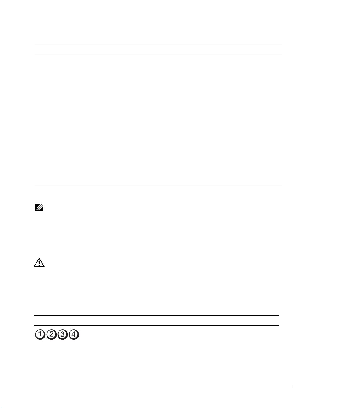
To help you troubleshoot a problem, your computer has four lights labeled "1," "2," "3," and "4" on the front.
The lights can be off or green. When the computer starts normally, the lights flash. After the computer
starts, all four lights display solid green briefly and then turn off to indicate normal operation. If the
computer malfunctions, the pattern of the lights identify the problem.
Light Pattern Problem Description Suggested Resolution
The computer is in a normal off
Plug the computer into a working
condition or a possible pre-BIOS
electrical outlet and press the power
failure has occurred.
button.
NOTE: The diagnostic lights turn off after
a short time if the computer is in a normal
operating condition after POST.
Quick Reference Guide 37
