Dell PowerEdge C8000 – page 2
Manual for Dell PowerEdge C8000
Table of contents
- Notes, Cautions, and Warnings
- CAUTION: Restricted Access Location Installation and Configuration Recommended Tools Unpacking the System
- Installing the Tool-Less Rail Solution Determine where to place the rails in the rack. Make sure there is enough space in the rack for the 4U chassis. In a standard rack, the height of a 4U chassis will span 12 rack post holes. Use the marking indicated on the left and right sides of the rail to orient the rail correctly to the rack posts. Attach the left rail and stopping bracket to the rack. a
- e f g
- h i
- 4 Attach the right rail and stopping bracket to the rack. Installing the System Emptying the System
- • To remove a • To remove a
- • To remove a power sled, pull up on the release latch • To remove a double-wide sled blank, squeeze and hold the release latches
- • To remove a single-wide sled blank, pull up on the release latch
- Install the System Into the Rack 1
- 2
- Sled Bay Numbering Sled Bays Sled module type
- Populating the System
- Install the External PDU Into the Rack 1 2
- 3 4
- 5 a
- d e
- 6
- Rack Configuration
- Connecting the Keyboard, Mouse, and Monitor
- Connecting the Power Cables Server Enclosure with Internal Power Source
- Server Enclosure with External Power Source
- Connecting the Server Enclosure to a Rack PDU To connect a single server enclosure to the PDU:
- To connect multiple server enclosures to the PDU:
- Close the cable cover and secure to the PDU.
- Connecting the PDU to the Network 1 a b
- c
- Powering Up the Systems Turning on the PDU 1 a b 2
- 3 4 Turning On the Server Enclosure
- Turning On the Sleds
- Complete the Operating System Setup Supported Operating Systems
- Other Information You May Need
- NOM Information PowerEdge C8000 PowerEdge C8220
- PowerEdge C8220X PowerEdge C8000XD
- Technical Specifications Compute Sled Specifications (Per Sled) System chipset Memory Storage device
- Compute Sled Specifications (Per Sled)(continued) Graphics card Expansion slots Interfaces Power
- Storage Sled Specifications (Per Sled) Storage device Interface Power Sled Specifications (Per Sled) Interfaces Power supply module (per power supply)
- Server Enclosure Specifications Physical Sled Support Interfaces System fans Power
- Environmental
- Environmental(continued)
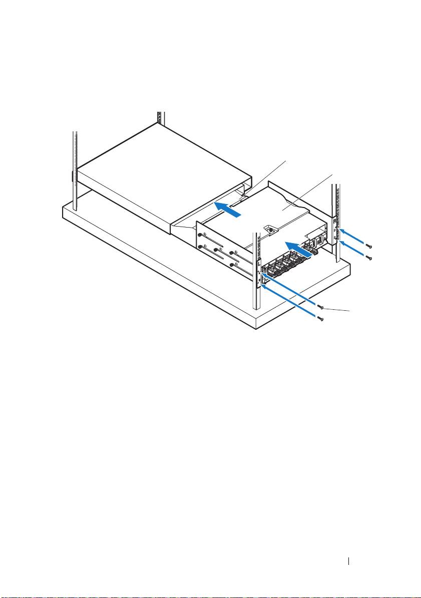
6
With assistance, slide the air duct
into the snorkel and secure the back
of the PDU
to the rack posts with four screws
.
Getting Started With Your System
19
1
2
FRONT
3
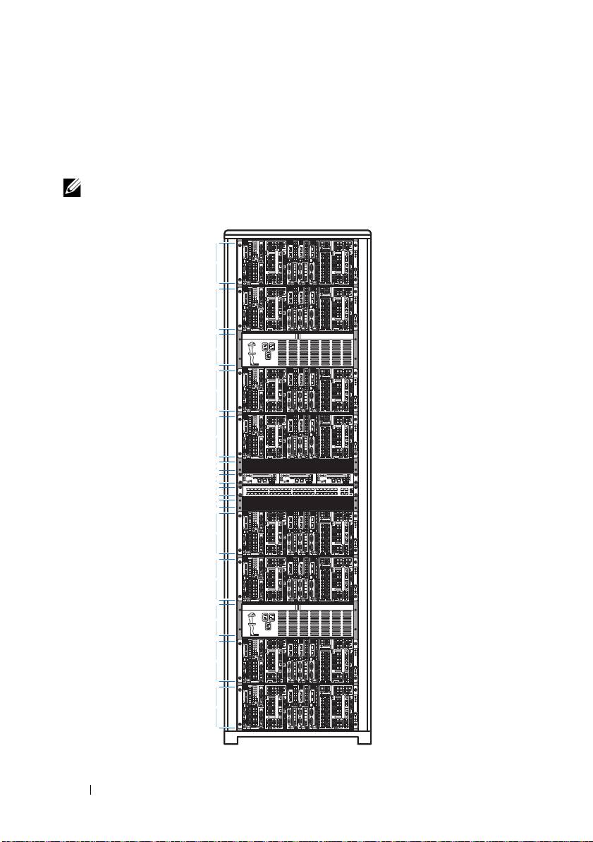
Rack Configuration
The following illustration shows a sample rack configuration with PowerEdge
C8000 server enclosures, power distribution unit (PDU) devices, switch and
router in a 42U rack.
NOTE:
The rack configuration illustration is provided as reference only.
20
Getting Started With Your System
4U
4U
3U
4U
4U
1U
1U
1U
1U
4U
4U
3U
4U
4U
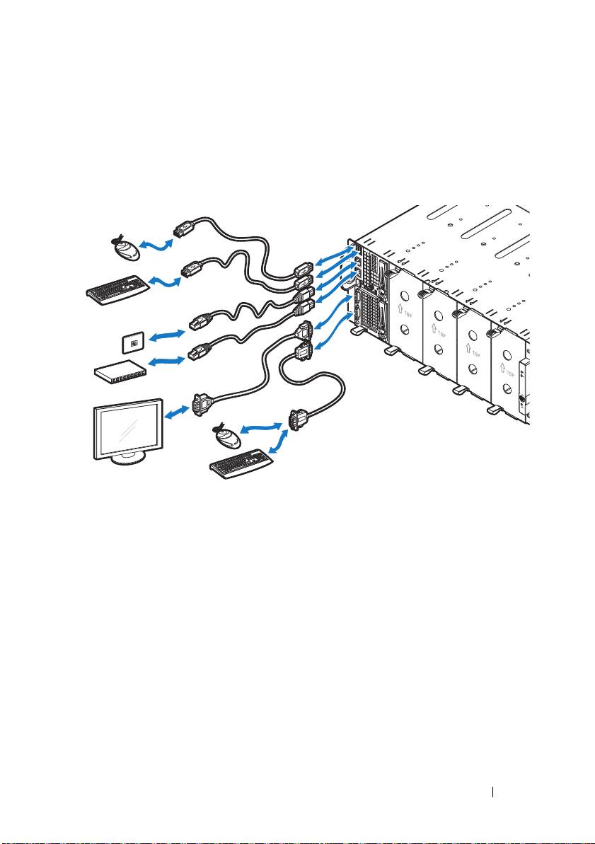
Connecting the Keyboard, Mouse, and Monitor
Connect a keyboard, mouse, and monitor to the compute sled (optional).
The following figure shows a sample keyboard, mouse, and monitor
connection to a C8220X double-wide compute sled.
Getting Started With Your System
21
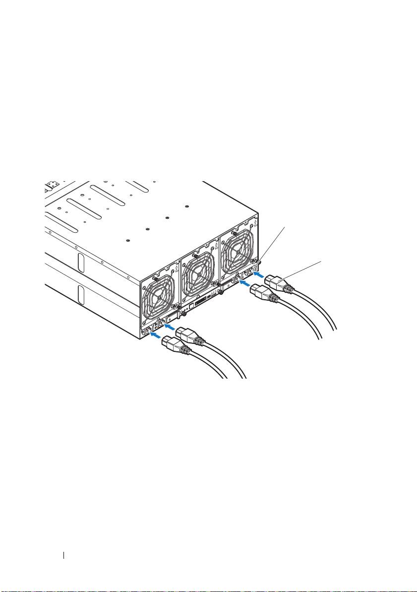
Connecting the Power Cables
This section includes instructions on how to connect the server enclosure
with internal or external power source to an external PDU.
Server Enclosure with Internal Power Source
1
On the back of the enclosure, connect the power cables
to the AC power
sockets
.
2
Plug the other end of the power cables into a grounded electrical outlet or
a separate power source such as an uninterrupted power supply or the
PDU.
22
Getting Started With Your System
2
1
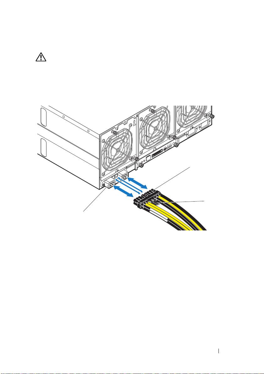
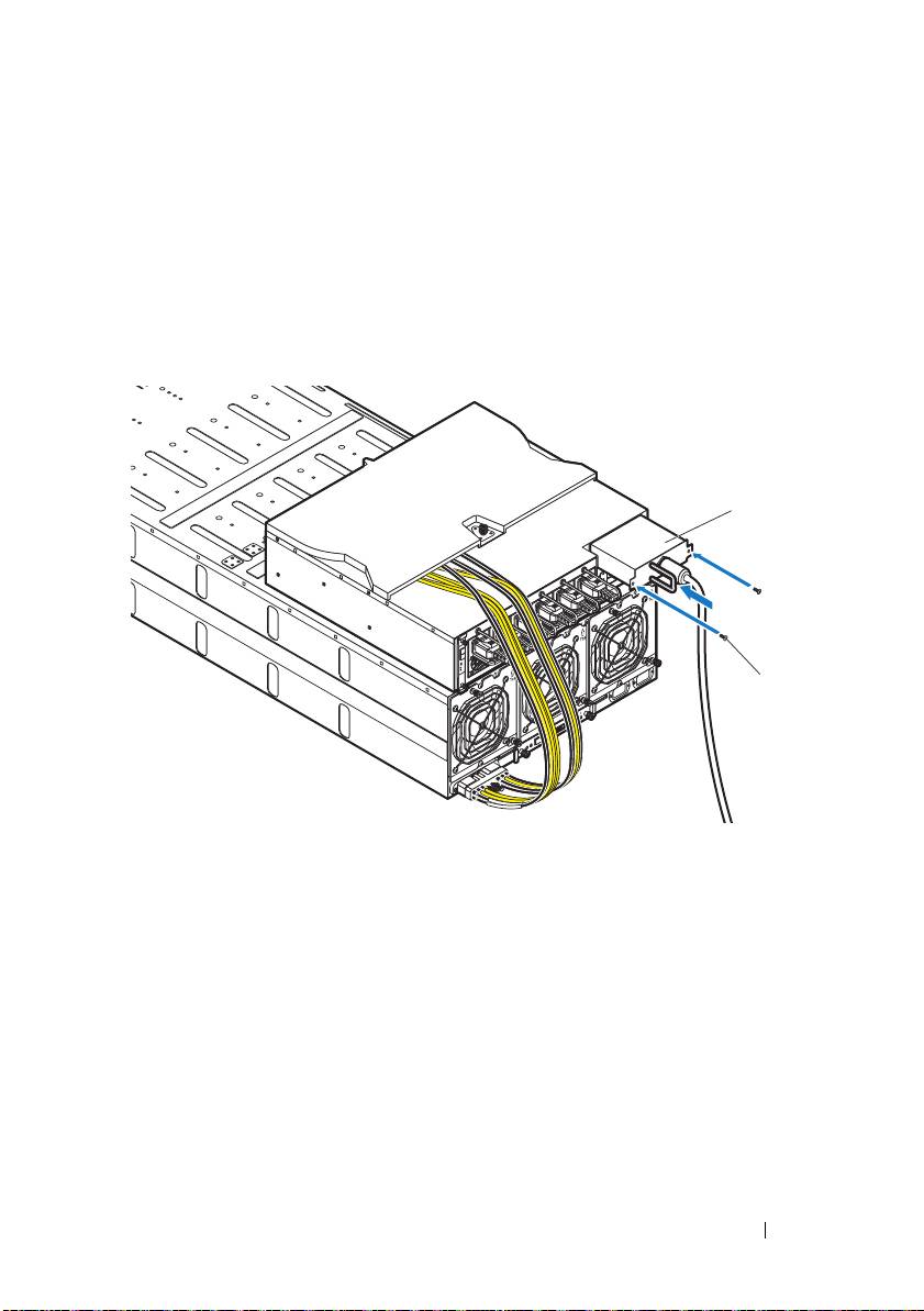
Server Enclosure with External Power Source
WARNING:
Make sure power is turned off on all devices before making
connections.
1
On the back of the enclosure, connect the power cable
to the DC power
socket
.
2
Tighten the two center screws
on the cable to secure the connection.
Getting Started With Your System
23
1
3
2
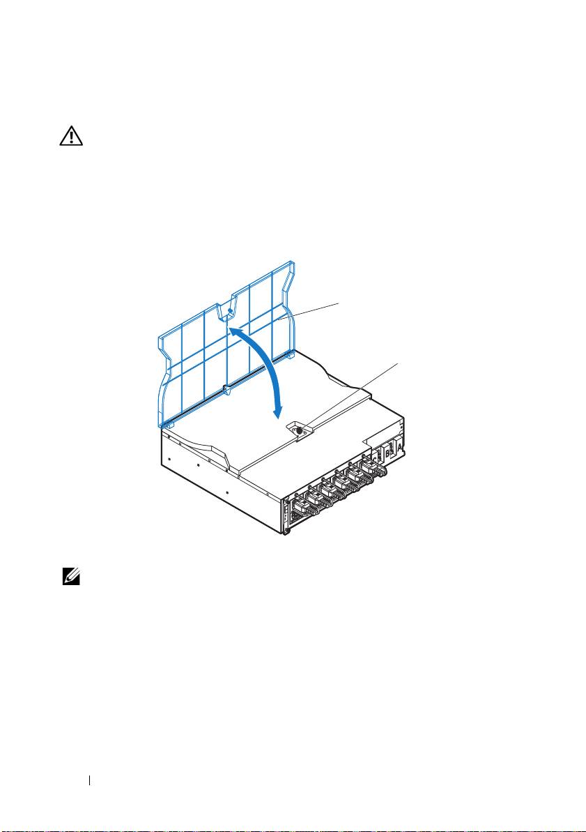
Connecting the Server Enclosure to a Rack PDU
WARNING:
Do not connect or disconnect power cables to the PDU device while
the PDU is energized. Turn off the PDU breaker switches to avoid potentially
serious or fatal electrical shock. Move the PDU A, B, and C breaker switches to
the "OFF" position.
1
Unlock the cable cover
.
2
Rotate the cover
back and away from the PDU.
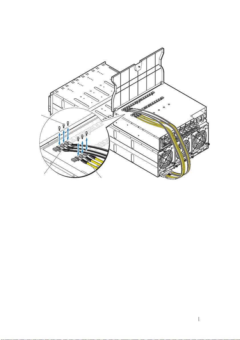
3
Attach the server enclosure(s) power cables to the PDU power bus bar.
NOTE:
The PDU device supports a maximum of five PowerEdge C8000 server
enclosures depending on the system configuration and power budget.
To connect a single server enclosure to the PDU:
a
Secure the three black power cable lugs
to the top power bus bar
(GND) with the three screws
.
b
Secure the three yellow power cable lugs
to the bottom power bus
bar with the three screws
.
24
Getting Started With Your System
2
1
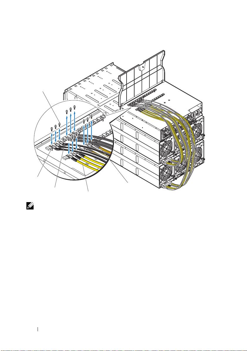
To connect multiple server enclosures to the PDU:
a
Secure the first server enclosure’s three black power cable lugs
to
the top power bus bar (GND) with the three screws
.
b
Secure the first server enclosure’s three yellow power cable lugs
to
the bottom power bus bar with the three screws
.
c
Secure the second server enclosure’s three black power cable lugs
to
the top power bus bar (GND) with the three screws
.
d
Secure the second server enclosure’s three yellow power cable lugs
to the bottom power bus bar with the three screws
.
Getting Started With Your System
25
3
1
2
NOTE:
Ensure that all power cords are connected properly and securely to the
PDU power bus bars.
4
Close the cable cover and secure to the PDU.
26
Getting Started With Your System
5
1
4
3
2
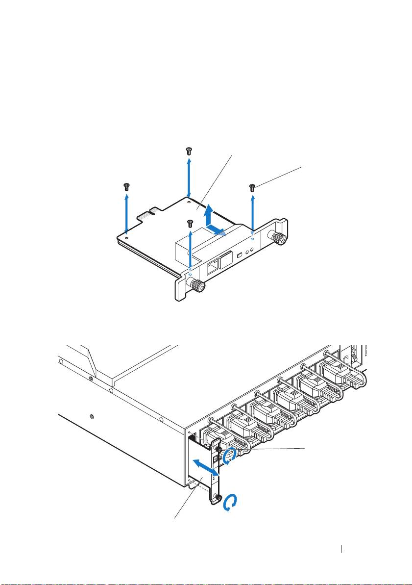
Connecting the PDU to the Network
1
Install the power management controller (PMC) into the PDU and
connect to your network.
a
Secure the PMC board
to the PMC tray with the four screws
.
b
Insert the PMC assembly
to the PDU and secure with the two
thumbscrews
.
Getting Started With Your System
27
1
2
2
1
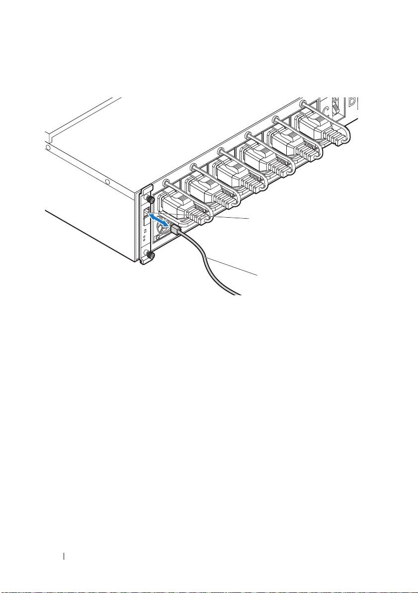
c
Connect the network cable
to the NIC port 1
.
28
Getting Started With Your System
2
1
Powering Up the Systems
Turning on the PDU
1
Install the PCIB module into the PDU.
a
Insert the PCIB module into the PCIB bay
.
b
Secure the PCIB module to the PDU with the two screws
.
2
Connect the PDU to the power source.
Getting Started With Your System
29
1
2
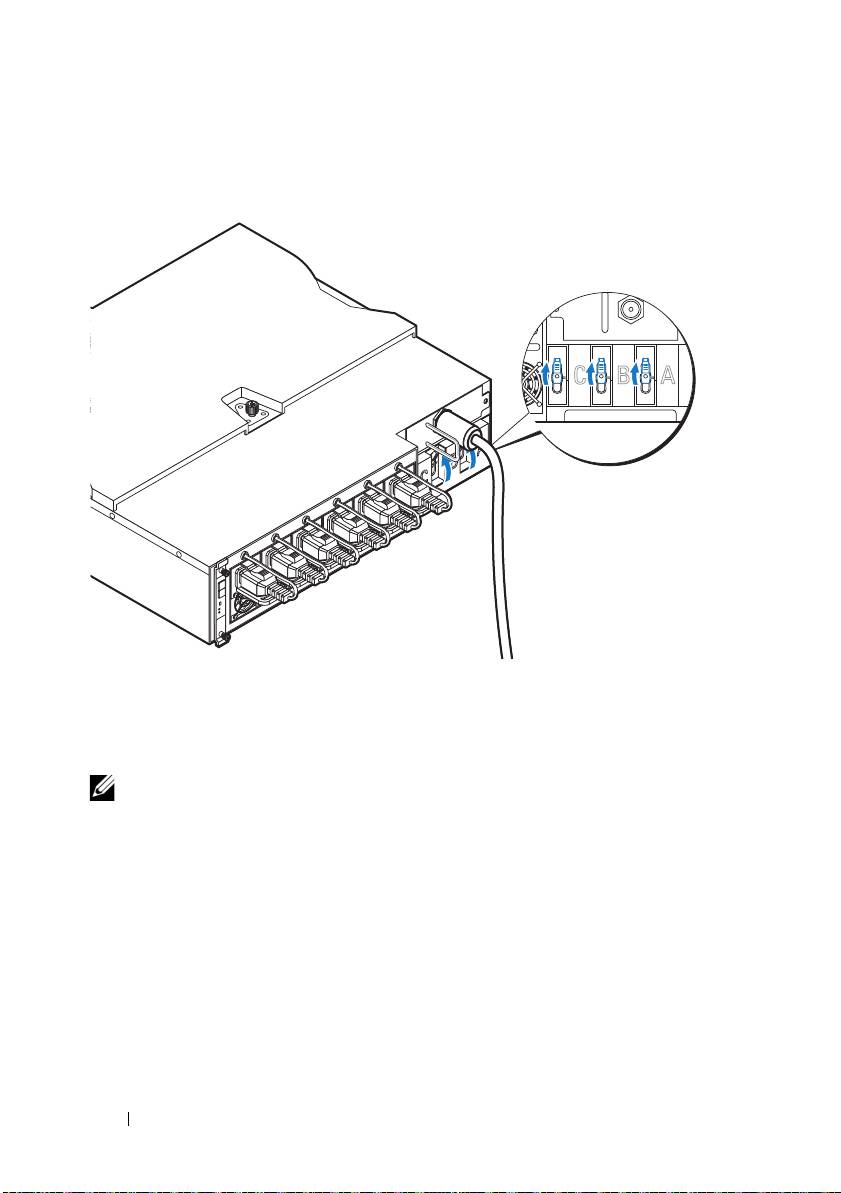
3
Turn on the PDU breaker switches by moving the A, B, and C breaker
switches to the "ON" position.
4
To enable monitoring of the PDU device over the network, turn on the
PMC board by pressing the power button, located on the PMC board.
When power is applied to the PDU, the power/status indicator on the
front of the PMC board will light up green.
NOTE:
The PMC board and PDU device illustrations in this guide are provided as
reference only. See PDU device documentation for more information about the
PMC board and PDU device.
Turning On the Server Enclosure
When connected to a power source, main power is automatically distributed
to the server enclosure. After the server enclosure is powered up the
power/event indicator on the front of the enclosure will light up green and
main power is applied to all sleds in the enclosure.
30
Getting Started With Your System
ONONON
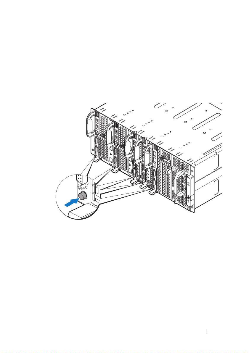
Turning On the Sleds
To turn on the C8220 or C8220X compute sled, press the power button on
each sled, or power on the sled using the baseboard management controller.
When power is applied to the sled, the power-on indicator on front of the sled
will light up green. When installed into the server enclosure, the C8000XD
storage sled automatically powers on. See Using the Baseboard Management
Controller Guide at dell.com/support/manuals.
Getting Started With Your System
31

Complete the Operating System
Setup
To install an operating system for the first time, see the installation and
configuration documentation for your operating system. Be sure the
operating system is installed before installing hardware or software not
purchased with the system.
Supported Operating Systems
• Citrix XenServer Enterprise Edition 5.6
• Citrix XenServer Enterprise Edition 6.1
• Microsoft Windows Server 2008 Enterprise Edition Release 2 (64-bit)
• Microsoft Windows Server 2012
• Microsoft Windows HPC 2008 Release 2
• Microsoft HyperV
• Red Hat Enterprise Linux 6.1 (64-bit)
• Red Hat Enterprise Linux 6.3 (64-bit)
• SUSE Linux Enterprise Server 11 SP2 (64-bit)
• Ubuntu 12.04.1 LTS 64-bit
• VMware ESXi 5.0
• VMware ESXi 5.0 U1
• VMware ESXi 5.0 U2
• VMware ESX 5.1
• VMware ESXi 5.1 U1
NOTE:
For the latest information on supported operating systems, see
dell.com/ossupport.
32
Getting Started With Your System
Other Information You May Need
WARNING:
See the safety and regulatory information that shipped with your
system. Warranty information may be included within this document or as a
separate document.
• The PowerEdge C8000 Hardware Owner’s Manual for information about
the server enclosure features, troubleshooting, and component
replacement. This document is available at
dell.com/support/manuals
.
• The PowerEdge C8220 Hardware Owner’s Manual for information about
system features, troubleshooting, and component replacement. This
document is available at
dell.com/support/manuals
.
• The PowerEdge C8220X Hardware Owner’s Manual for information about
system features, troubleshooting, and component replacement. This
document is available at
dell.com/support/manuals
.
• The PowerEdge C8000XD Hardware Owner’s Manual for information
about system features, troubleshooting, and component replacement. This
document is available at
dell.com/support/manuals
.
• The Baseboard Management Controller Guide provides information about
installing and using the systems management utility. This document is
available at
dell.com/support/manuals
.
NOTE:
Always check for updates and read the updates first because they often
supersede information in other documents.
Getting Started With Your System
33

NOM Information
PowerEdge C8000
The following information is provided on the device described in this
document in compliance with the requirements of the official Mexican
standards (NOM):
Importer: Dell Inc. de México, S.A. de C.V.
Paseo de la Reforma 2620-11° Piso
Col. Lomas Altas
11950 México, D.F.
Model number: B10S
Supply voltage: 200–240 V CA (with four 1400 W AC Power Supply Unit) or
12 V DC (with external PDU)
Frequency: 50–60 Hz
Current consumption: 9 A (x4) (with four 1400 W AC Power Supply Unit) or
480 A (with external PDU)
PowerEdge C8220
The following information is provided on the device described in this
document in compliance with the requirements of the official Mexican
standards (NOM):
Importer: Dell Inc. de México, S.A. de C.V.
Paseo de la Reforma 2620-11° Piso
Col. Lomas Altas
11950 México, D.F.
Model number: B05B
Supply voltage: 12 V DC
Current consumption: 42 A
34
Getting Started With Your System

PowerEdge C8220X
The following information is provided on the device described in this
document in compliance with the requirements of the official Mexican
standards (NOM):
Importer: Dell Inc. de México, S.A. de C.V.
Paseo de la Reforma 2620-11° Piso
Col. Lomas Altas
11950 México, D.F.
Model number: B06B
Supply voltage: 12 V DC
Current consumption: 92 A
PowerEdge C8000XD
The following information is provided on the device described in this
document in compliance with the requirements of the official Mexican
standards (NOM):
Importer: Dell Inc. de México, S.A. de C.V.
Paseo de la Reforma 2620-11° Piso
Col. Lomas Altas
11950 México, D.F.
Model number: B06B
Supply voltage: 12 V DC
Current consumption: 30 A
Getting Started With Your System
35

Technical Specifications
Compute Sled Specifications (Per Sled)
Processor
Processor type Two Intel Xeon E5 series processors
Processor socket Two LGA 2011
System chipset
Platform Controller Hub Intel X79
Network Controller Intel i350-BT2
Video Controller Aspeed AST2300
Memory
Memory type DDR3 UDIMM, RDIMM, LRDIMM
Memory module sockets 16 DIMM sockets
Memory module capacities 2 GB, 4 GB, 8 GB, 16 GB, and 32 GB
RDIMMs
Minimum RAM 512 MB UDIMM; 1 GB RDIMM
Maximum RAM 128 GB UDIMMs; 256 GB RDIMMs
No. of memory channels (Per CPU) 4 channels
Storage device
PowerEdge C8220 single-wide
• 3 Gb/s SATA port x 4
compute sled
• 6 Gb/s SATA port x 2
• 2.5-inch SATA HDDs x2
PowerEdge C8220X double-wide
• 3 Gb/s SATA port x 4
compute sled
• 6 Gb/s SATA port x 2
• 2.5-inch SATA HDDs x 2
• 2.5-inch SAS/SATA HDDs x 8 or
3.5-inch SAS/SATA HDDs x 4
• 2.5-inch hot-plug SAS/SATA HDDs x 2
(PowerEdge C8220X with front-access
2.5-inch hot-plug hard drives)
36
Getting Started With Your System

Compute Sled Specifications (Per Sled)(continued)
Graphics card
PowerEdge C8220X double-wide
PowerEdge C8220X with GPGPU/MIC
compute sled
• NVIDIA Tesla M2090
• NVIDIA Tesla K20
• Intel Xeon Phi 5110P
Expansion slots
PowerEdge C8220 single-wide
• One x16 PCI Express 2.0 slot
compute sled
• One x8 mezzanine slot
PowerEdge C8220X double-wide
• Two x8 PCI Express 3.0 slot (x16 connector
compute sled
type)
• One x8 mezzanine slot
PowerEdge C8220X with
• One x16 PCI Express 3.0 slot via single riser
GPGPU/MIC double-wide
• One x16 PCI Express 3.0 slot via cable
compute sled
• One x8 mezzanine slot
Interfaces
BMC management port 1 front
NIC Two 1Gb NIC ports
Serial 1 front
VGA 1 front
USB 2 front
UID LED 1 front
Power
Batteries
System battery
CR 2032 3.0-V lithium ion coin cell
RAID battery (optional)
3.7 V lithium ion battery pack
Getting Started With Your System
37

Storage Sled Specifications (Per Sled)
HDD Sled Configuration
Dual port mode (redundant) Standard carrier
Single port mode (non-redundant)
• Standard carrier
• Flexible carrier
• Expansion carrier
Expansion mode (non-zoning/
Expansion carrier
two zone/four zone)
Storage device
Standard carrier 3.5-inch SAS/SATA/SSD HDD x 12
Flexible carrier 2.5-inch SAS/SATA/SSD HDD x 12
Expansion carrier 2.5-inch SSD HDD x 24
Interface
Mini-SAS 4 front
Power Sled Specifications (Per Sled)
Interfaces
Power LED 2 front
Power connector 2 DC connector (12 V & GND)
Power supply module (per power supply)
Wattage 1400 W
Connector IEC C20
Voltage 200–240 V AC, 50–60 Hz, 9 A max
Heat dissipation 1205 BTU/hr. maximum
Maximum inrush current Under typical line conditions and over the
entire system ambient operating range, the
inrush current may reach 25 A per power
supply for 10 ms or less
38
Getting Started With Your System
