Dell PowerEdge C8000: 3 4 Turning On the Server Enclosure
3 4 Turning On the Server Enclosure: Dell PowerEdge C8000
Table of contents
- Notes, Cautions, and Warnings
- CAUTION: Restricted Access Location Installation and Configuration Recommended Tools Unpacking the System
- Installing the Tool-Less Rail Solution Determine where to place the rails in the rack. Make sure there is enough space in the rack for the 4U chassis. In a standard rack, the height of a 4U chassis will span 12 rack post holes. Use the marking indicated on the left and right sides of the rail to orient the rail correctly to the rack posts. Attach the left rail and stopping bracket to the rack. a
- e f g
- h i
- 4 Attach the right rail and stopping bracket to the rack. Installing the System Emptying the System
- • To remove a • To remove a
- • To remove a power sled, pull up on the release latch • To remove a double-wide sled blank, squeeze and hold the release latches
- • To remove a single-wide sled blank, pull up on the release latch
- Install the System Into the Rack 1
- 2
- Sled Bay Numbering Sled Bays Sled module type
- Populating the System
- Install the External PDU Into the Rack 1 2
- 3 4
- 5 a
- d e
- 6
- Rack Configuration
- Connecting the Keyboard, Mouse, and Monitor
- Connecting the Power Cables Server Enclosure with Internal Power Source
- Server Enclosure with External Power Source
- Connecting the Server Enclosure to a Rack PDU To connect a single server enclosure to the PDU:
- To connect multiple server enclosures to the PDU:
- Close the cable cover and secure to the PDU.
- Connecting the PDU to the Network 1 a b
- c
- Powering Up the Systems Turning on the PDU 1 a b 2
- 3 4 Turning On the Server Enclosure
- Turning On the Sleds
- Complete the Operating System Setup Supported Operating Systems
- Other Information You May Need
- NOM Information PowerEdge C8000 PowerEdge C8220
- PowerEdge C8220X PowerEdge C8000XD
- Technical Specifications Compute Sled Specifications (Per Sled) System chipset Memory Storage device
- Compute Sled Specifications (Per Sled)(continued) Graphics card Expansion slots Interfaces Power
- Storage Sled Specifications (Per Sled) Storage device Interface Power Sled Specifications (Per Sled) Interfaces Power supply module (per power supply)
- Server Enclosure Specifications Physical Sled Support Interfaces System fans Power
- Environmental
- Environmental(continued)
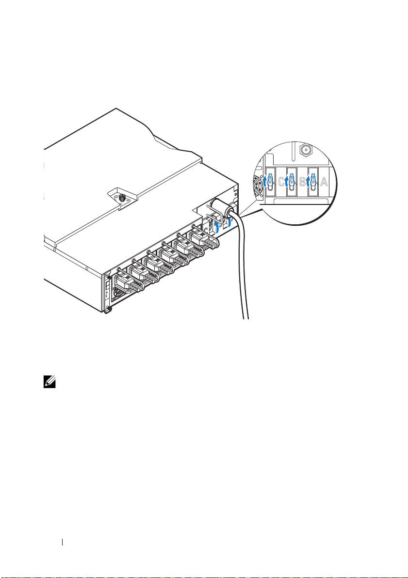
3
Turn on the PDU breaker switches by moving the A, B, and C breaker
switches to the "ON" position.
4
To enable monitoring of the PDU device over the network, turn on the
PMC board by pressing the power button, located on the PMC board.
When power is applied to the PDU, the power/status indicator on the
front of the PMC board will light up green.
NOTE:
The PMC board and PDU device illustrations in this guide are provided as
reference only. See PDU device documentation for more information about the
PMC board and PDU device.
Turning On the Server Enclosure
When connected to a power source, main power is automatically distributed
to the server enclosure. After the server enclosure is powered up the
power/event indicator on the front of the enclosure will light up green and
main power is applied to all sleds in the enclosure.
30
Getting Started With Your System
ONONON
