Beurer BM 75 – page 7
Manual for Beurer BM 75
Table of contents
- 2. Important information 1. Getting to know your instrument Signs and symbols
- Advice on use
- Advice on batteries Storage and Care Repair and disposal
- 3. Device description
- Information on the display: USB interface System requirements for the Beurer „HealthManager“ PC software
- 4. Preparing the measurement Setting the hour format, date and time Inserting the batteries
- 5. Measuring blood pressure Positioning cuff Operation with the mains part
- Performing the blood pressure measurement Correct posture
- WHO classification: 6. Evaluating results Cardiac arrhythmia:
- Range of blood pressure values Systolic Resting indicator measurement (using HSD diagnostics) RED: Lack of haemodynamic stability GREEN: Haemodynamic stability
- 7. Displaying and deleting measurements
- 8. Transferring measurements USB interface NFC
- 9. Cleaning and storing the instrument 11. Specifications 10. Rectifying faults
- 12. Mains part
Część 1: Wymagania ogólne), EN1060-3 (Nieinwazyjne sfig-
Posiada izolację ochronną /
momanometry – Część 3: Wymagania dodatkowe dotyczące
Klasa ochronna 2
elektromechanicznych systemów do pomiaru ciśnienia krwi)
Obudowa i pokry-
Obudowa adaptera chroni przed kontak-
oraz IEC80601-2-30 (Medyczne urządzenia elektryczne,
wa ochronna
tem z częściami, które przewodzą wzgl.
część 2 – 30: Szczególne ustalenia dotyczące bezpieczeń-
mogłyby przewodzić prąd (palce, igły, hak
stwa wraz z istotnymi danymi z zakresu wydajności dla
testowy).
automatycznych, nieinwazyjnych ciśnieniomierzy).
Użytkownikowi nie wolno jednocześnie
•
Dokładność niniejszego ciśnieniomierza została starannie
dotykać pacjenta i wtyczki wyjściowej
sprawdzona i dostosowana do długiego okresu użytkowania.
adaptera AC.
Stosowanie urządzenia w lecznictwie wymaga technicznych
pomiarów kontrolnych za pomocą odpowiednich przyrzą-
dów. Dokładne dane dotyczące kontroli dokładności można
uzyskać w serwisie pod podanym poniżej adresem.
12. Adapter
Nr modelu FW 7575M/EU/6/06
Wejście 100 – 240 V, 50 – 60 Hz
Wyjście 6 V DC, 600 mA tylko w połączeniu z
ciśnieniomierzami firmy Beurer.
Producent Friwo Gerätebau GmbH
Ochrona Urządzenie posiada podwójną izolację
ochronną oraz wbudowane zabezpiecze-
nie termiczne, które odłącza je od sieci w
przypadku awarii.
Przed rozpoczęciem pracy z adapterem
należy upewnić się, że baterie zostały wy-
jęte z kieszeni baterii.
Biegunowość przyłącza napięcia stałego
121
Electromagnetic Compatibility Information
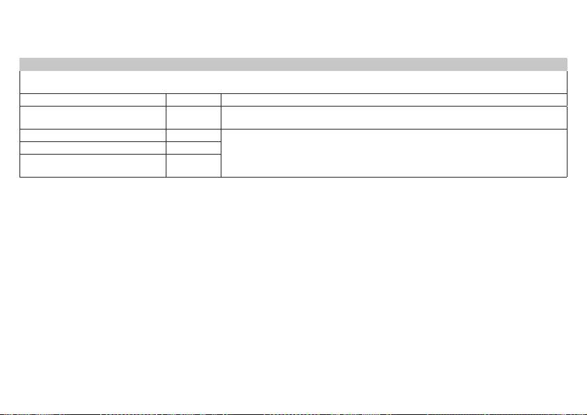
Table 1
For all ME EQUIPMENT and ME SYSTEMS
Guidance and manufacture’s declaration – electromagnetic emissions
The BM 75 is intended for use in the electromagnetic environment specified below.
The customer or the user of the BM 75 should assure that it is used in such an environment.
Emissions test Compliance Electromagnetic environment – guidance
RF emissions CISPR 11 Group 1
The BM 75 uses RF energy only for its internal function. Therefore, its RF emissions are very
low and are not likely to cause any interference in nearby electronic equipment.
RF emissions CISPR 11 Class B The BM 75 is suitable for use in all establishments, including domestic establishments and
those directly connected to the public low-voltage power supply network that supplies buil-
Harmonic emissions IEC 61000-3-2 Class A
dings used for domestic purposes.
Voltage fluctuations/flicker emissions
Complies
IEC 61000-3-3
122

Table 2
Guidance and manufacturer’s declaration – electromagnetic immunity
The BM 75 is intended for use in the electromagnetic environment specified below. The customer or the user of the BM 75 should assure that it is
used in such an environment.
Immunity test IEC 60601 test level Compliance level Electromagnetic environment – guidance
Floors should be wood, concrete or ceramic tile. If
Electrostatic discharge (ESD)
± 6 kV contact
± 6 kV contact
floors are covered with synthetic material, the relative
IEC 61000-4-2
± 8 kV air
± 8 kV air
humidity should be at least 30 %.
Electrical fast transient/burst
± 2 kV for power supply lines
± 2 kV for power supply lines
Mains power quality should be that of a typical com
-
IEC 61000-4-4
± 1 kV for input/output lines
N/A
mercial or hospital environment.
Surge
± 1 kV line(s) to line(s)
± 1 kV dierential mode
Mains power quality should be that of a typical com-
IEC 61000-4-5
± 2 kV line(s) to earth
N/A
mercial or hospital environment.
<5 % U
T
(>95 % dip in U
T
)
<5 % U
T
(>95 % dip in U
T
)
Mains power quality should be that of a typical com-
for 0.5 cycle
for 0.5 cycle
mercial or hospital environment. If the user of the BM
75
Voltage dips, short interrup-
40 % U
T
(60 % dip in U
T
)
40 % U
T
(60 % dip in U
T
)
requires continued operation during power mains inter-
tions and voltage variations
for 5 cycles
for 5 cycles
ruptions, it is recommended that the BM 75 be powered
on power supply input lines
70 % U
T
(30 % dip in U
T
)
70 % U
T
(30 % dip in U
T
)
from an uninterruptible power supply or a battery.
IEC 61000-4-11
for 25 cycles
for 25 cycles
<5 % U
T
(>95 % dip in U
T
)
<5 % U
T
(>95 % dip in U
T
)
for 5 s
for 5 s
Power frequency magnetic fields should be at levels
Power frequency (50/60 Hz)
3 A/m 3 A/m
characteristic of a typical location in a typical commer
-
magnetic field IEC 61000-4-8
cial or hospital environment.
NOTE: U
T
is the a.c. mains voltage prior to application of the test level.
123
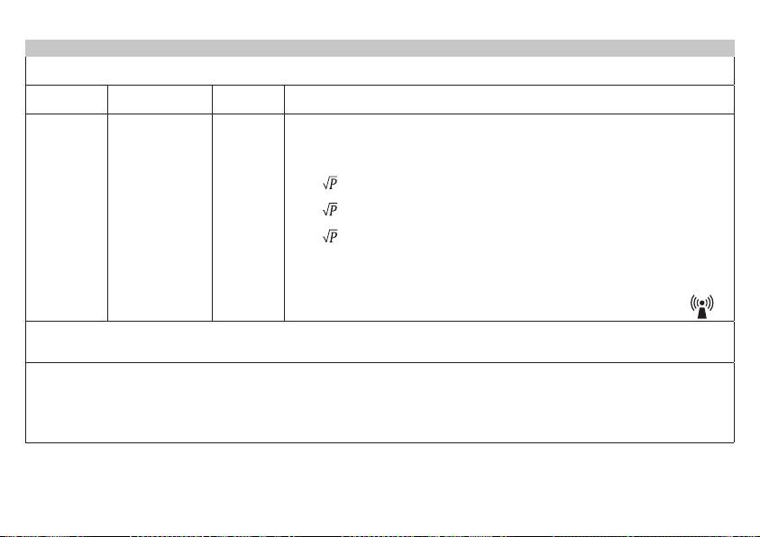
Table 3
Guidance and manufacturer’s declaration – electromagnetic immunity
The BM 75 is intended for use in the electromagnetic environment specified below. The customer or the user of the BM 75 should assure that it is
used in such an environment.
Immunity test IEC 60601 test
Compliance
Electromagnetic environment – guidance
level
level
Portable and mobile RF communications equipment should be used no closer to any part of
the BM 75, including cables, than the recommended separation distance calculated from the
equation applicable to the frequency of the transmitter.
Recommended separation distance:
Conducted RF
3 V
d = 1.2
rms
IEC 61000-4-6
3 V
rms
150 kHz to 80 MHz
d = 1.2 80 MHz to 800 MHz
Radiated RF
3 V/m
3 V/m
d = 2.3
800 MHz to 2.5 GHz
IEC 61000-4-3
80 MHz to 2.5 GHz
Where P is the maximum output power rating of the transmitter in watts (W) according to the
transmitter manufacturer and d is the recommended separation distance in meters (m).
Field strengths from fixed RF transmitters, as determined by an electromagnetic site survey,
a
should be less than the compliance level in each frequency range.
b
Interference may occur in the vicinity of equipment marked with the following symbol:
NOTE 1 At 80 MHz and 800 MHz, the higher frequency range applies.
NOTE 2 These guidelines may not apply in all situations. Electromagnetic propagation is aected by absorption and reflection from structures,
objects and people.
a
Field strengths from fixed transmitters, such as base stations for radio (cellular/cordless) telephones and land mobile radios, amateur radio, AM and
FM radio broadcast and TV broadcast cannot be predicted theoretically with accuracy. To assess the electromagnetic environment due to fixed RF
transmitters, an electromagnetic site survey should be considered. If the measured field strength in the location in which the BM 75 is used exceeds
the applicable RF compliance level above, the BM 75 should be observed to verify normal operation. If abnormal performance is observed, additio-
nal measures may be necessary, such as re-orienting or relocating the BM 75.
b
Over the frequency range 150 kHz to 80 MHz, field strengths should be less than 3 V/m.
124
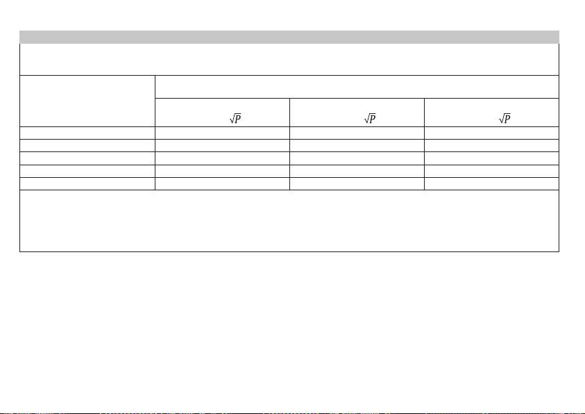
Table 4
Recommended separation distances between portable and mobile RF communications equipment and the BM 75
The BM 75 is intended for use in an electromagnetic environment in which radiated RF disturbances are controlled. The customer or the user of the
BM 75 can help prevent electromagnetic interference by maintaining a minimum distance between portable and mobile RF communications equip-
ment (transmitters) and the BM 75 as recommended below, according to the maximum output power of the communications equipment.
Separation distance according to frequency of transmitter
(m)
Rated maximum output
150 kHz to 80 MHz
80 MHz to 800 MHz
800 MHz to 2.5 GHz
power of transmitter
(W)
d = 1.2
d = 1.2
d = 2.3
0.01 0.12 0.12 0.23
0.1 0.38 0.38 0.73
1 1.2 1.2 2.3
10 3.8 3.8 7.3
100 12 12 23
For transmitters rated at a maximum output power not listed above, the recommended separation distance d in meters (m) can be determined using
the equation applicable to the frequency of the transmitter, where P is the maximum output power rating of the transmitter in watts (W) according to
the transmitter manufacturer.
NOTE 1 At 80 MHz and 800 MHz, the separation distance for the higher frequency range applies.
NOTE 2 These guidelines may not apply in all situations. Electromagnetic propagation is aected by absorption and reflection from structures,
objects and people.
125

126

127

750.280 - 0115 Irrtum und Änderungen vorbehalten
128
