Hama VMPL2: ENGLISH
ENGLISH: Hama VMPL2
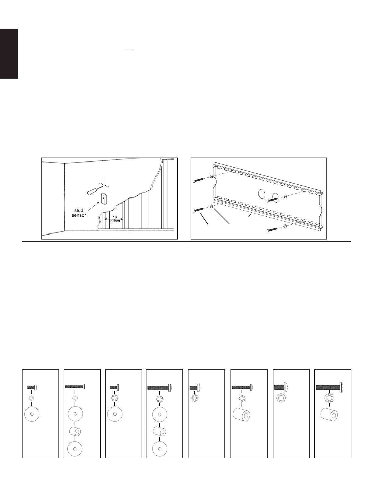
Step 1: Mounting the Wall Plate: Wood Stud, Brick, Solid Concrete, and Concrete Block mounting options are provided.
Wood Stud mounting:
The Wall Plate (a) must be mounted to two wood studs at least 12" apart. Use a high quality stud sensor to locate two adjacent
studs. It is a good idea to verify where the studs are located with an awl or thin nail shown in Diagram 1a. Pre-drill a 2.5" deep hole at
the desired height in each stud using a 3/16" drill bit. Make sure these holes are in the center area of the studs and level with each other.
Use the Wall Plate as a template to mark the location of the second hole in each stud. Drill 2.5" deep holes using the 3/16" drill bit in the
ENGLISH
marked location. Attach the Wall Plate to the wall using the four 1/4 x 2.5” Lag Bolts (u) and four Lag Bolt Washers (s). Make sure the
Wall Plate is oriented so the flat surface in the center of the plate is against the wall and that a set of Lag Bolts is on each side of the two
large holes in the center as shown in Diagram 1b.
Brick, Solid Concrete and Concrete Block mounting:
Use the Wall Plate (a) as a template to mark 6 hole locations on the wall. The outer holes must fall to left and right of the two large holes
in the middle of the plate. Three in the top row of slots and three more in the bottom row. Make sure these holes are level and there is at
least 6" between any two holes. Pre-Drill these holes with a 1/2" masonry bit to at least 2.5" in depth. Insert a Concrete Anchor (v) into
each of these holes. Make sure the anchor is seated completely flush with the concrete surface even if there is a layer of drywall or other
material in front. Attach the Wall Plate to the wall using 6 Lag Bolts (u) and 6 Lag Bolt Washers (s).
Diagram 1a Diagram 1b
a
u s
Step 2: Select the Appropriate Hardware for your television
Always make sure the television is unplugged before threading any bolt into the back panel!
Thread bolts carefully into your television by hand before tightening. If you feel resistance, remove the bolt immediately! If you
are unable to find appropriate hardware for your television, consult a local hardware store or call Sanus Systems.
Locate the threaded inserts on the back of your flat panel television and determine which of the provided Bolts is the correct diameter.
To test each diameter, thread the Bolts carefully into your television by hand until you find the diameter that correctly fits.
Next, determine the correct length of the required Bolt. Televisions with a flat back will require one of the shorter Bolts without a spacer.
Some televisions have a curved back or have recessed threaded inserts. This may require a longer Bolt along with a Spacer placed be-
tween the television and the Monitor Bracket.
Once you have the correct bolt picked out, you can follow the diagrams below to see what additional hardware you will need to mount
the Monitor Brackets (c) to your television. For a television with a flat back, see Step 3 for installation instructions. For a television with
a curved back see Step 4. For a television that has a back with recessed threaded inserts see Step 5.
Hardware Diagrams:
M4 x 12
M4 x 30
M5 x 12
M5 x 30
M6 x 12
M6 x 35
M8 x 16
M8 x 40
e f g h i j k l
m m n n o o p p
t t t t r r
q q
t t
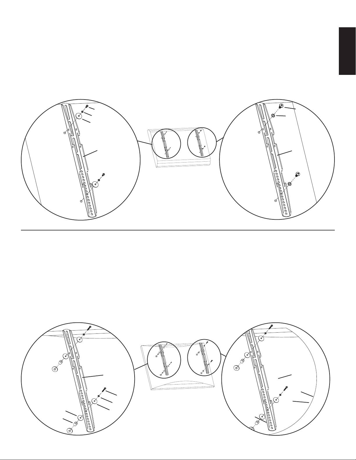
Step 3: Attaching the Monitor Brackets to a TV with a flat back
ENGLISH
WARNING: DO NOT LAY THE TELEVISION FACE DOWN ON THE GLASS, lean it up against a wall or other solid surface!
Laying the television down on the glass may cause permanent damage.
The Monitor Brackets (c) should be placed as vertically close to center of the television as possible before installation. For a flat back TV
that requires the M4 or M5 diameter Bolt, thread a M4 x 12 (e) or a M5 x 12 (g) Bolt through the appropriate Lock Washer (m,n), an M4/
M5 Washer (t), the Monitor Bracket and finally into the TV. See Detailed View A of Diagram 3 for assistance. If your TV requires the M6
or M8 diameter Bolt thread a M6 x 12 (i) or a M8 x 16 (k) Bolt through the appropriate Lock Washer (o,p), through the Monitor Bracket
and into the TV. See Detailed View B of Diagram 3 for assistance. Proceed to tighten the Bolts firmly with a phillips screw driver.
Detailed View A Detailed View B
e,g i,k
m,n Diagram 3 o,p
t
c c
Step 4: Attaching the Monitor Brackets to a television with a curved back
WARNING: DO NOT LAY THE TELEVISION FACE DOWN ON THE GLASS, lean it up against a wall or other solid surface!
Laying the television down on the glass may cause permanent damage.
The Monitor Brackets (c) should be placed as vertically close to center of the television as possible before installation. If your TV has
a curved back and requires either a M4 or M5 diameter bolt, thread a M4 x 30 (f) or a M5 x 30 (h) Bolt through the appropriate Lock
Washer (m,n), an M4/M5 Washer (t), the Monitor Bracket, an M4/M5 Washer, a M4/M5 Spacer (q) and into the TV as seen in Detailed
View A of Diagram 4. If you determined that your TV requires a Bolt with a M6 or M8 Diameter, thread a M6 x 35 (j) or a M8 x 40 (l)
Bolt through the appropriate Lock Washer (o,p), the Monitor Bracket, a M6/M8 Spacer (r) and into the TV as seen in Detailed View B
of Diagram 4. Proceed to tighten the Bolts firmly with a phillips screw driver.
Detailed View A Detailed View B
Diagram 4
c c
f, h j,l
m,n o,p
t t
q r
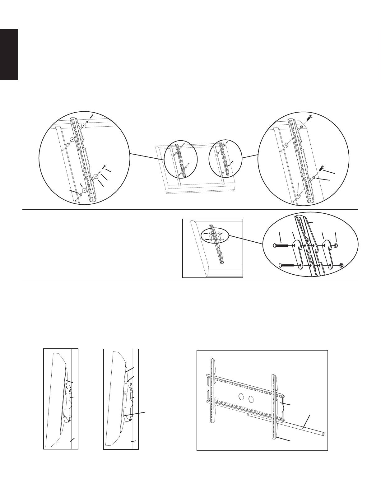
Step 5: Attaching the Monitor Brackets to a television with recessed threaded inserts.
WARNING: DO NOT LAY THE TELEVISION FACE DOWN ON THE GLASS, lean it up against a wall or other solid surface!
Laying the television down on the glass may cause permanent damage.
The Monitor Brackets (c) should be placed as vertically close to center of the television as possible before installation. If your TV has
threaded inserts that are recessed and requires either a M4 or M5 diameter bolt, thread a M4 x 30 (f) or a M5 x 30 (h) Bolt through the
ENGLISH
appropriate Lock Washer (m,n), an M4/M5 Washer (t), the Monitor Bracket, an M4/M5 Washer, a M4/M5 Spacer (q) and into the TV as
seen in Detailed View A of Diagram 5. If you determined that your TV requires a Bolt with a M6 or M8 Diameter, thread a M6 x 35 (j)
or a M8 x 40 (l) Bolt through the appropriate Lock Washer (o,p), the Monitor Bracket, a M6/M8 Spacer (r) and into the TV as seen in
Detailed View B of Diagram 5. Proceed to tighten the Bolts firmly with a phillips screw driver.
Detailed View A Detailed View B
Diagram 5
f,h j,l
t m,n r o,p
q t
Diagram 6 Detailed View
Step 6: Choose mounting position:
c
w d d x
You can mount your television in either of two positions:
flat or at a 5 degree downward tilt. To mount the television
flat to the wall use only the Monitor Brackets (c). To mount
the television in the 5 degree tilt position you must first add
two Gussets (d) to each Monitor Bracket with two Carriage
Bolts (w) and two Gusset Nuts (x) as shown in Diagram 6.
Step 7: Hang the TV onto the Wall Plate:
First hook the Monitor Brackets (c) over the top of the Wall Plate (a), then let the bottom of the Monitor Brackets rotate in under the
bottom of the Wall Plate. This process is shown with the flat mount option in Diagram 7a, and with the 5 degree tilt option in Diagram
7b. Once the TV is in place, insert the Safety Bar (b) into the slots in the bottom of the Monitor Brackets so that it sits behind the bottom
tab on the Wall Plate as shown in Diagram 7c. The bend should face toward the wall. Once the bar passes out the other side of the Wall
Plate a padlock can be added to the hole in the Safety Bar for additional security.
Diagram 7a Diagram 7b Diagram 7c
c
d
c
a a
a
slot for safety bar b
wall wall c
Оглавление
- ENGLISH ESPAÑOL DEUTSCH FRANÇAIS ITALIANO PYCCKO Spanish German French Italian Russian Japanese Mandarin
- ENGLISH Assembly Instructions for VMPL2 Flat Panel Wall Mount
- ENGLISH
- ESPAÑOL
- DEUTSCH
- FRANÇAIS
- ITALIANO
- Инструкция по сборке настенного крепления для плоскопанельных телевизоров VMPL2
- PYCCKO
- VMPL2 フラットパネル壁掛け装置の組み立て説明書
- M4 x 12 M4 x 30 M5 x 12 M5 x 30 M6 x 12 M6 x 35 M8 x 16 M8 x 40
- VMPL2 平板墙架装配说明
- M4 x 12 M4 x 30 M5 x 12 M5 x 30 M6 x 12 M6 x 35 M8 x 16 M8 x 40
- 中文
