Festool OF 2200 EB:
: Festool OF 2200 EB
16
Clamp the machine in this position by tighten-
ing the rotary knob [5.1].
Press the depth stop [5.3] against one of the
three fi xed stops on the rotary stepped stop
[5.4].
Slide the indicator [5.5] down to the 0 mm mark
on the scale [5.7].
If the base position of the indicator is incor-
rect, this can be adjusted by turning the screw
[5.6] on the indicator.
The stepped stop [Fig. 7] has three stops, two of
which can be adjusted in height using a screw-
driver:
Stop
Height
A
18 mm - 51 mm
B
6 mm - 18 mm
C
0 mm
Stop C has an offset for preliminary routing -
see "Preliminary/Fine routing".
b) Presetting the routing depth
Pull the depth stop [6.6] upwards until the indi-
cator [6.2] reaches the required routing depth.
Clamp the depth stop in this position using the
clamp lever [6.3].
Unscrew the rotary knob [6.1]. The machine is
now in starting position.
If necessary, you can readjust the routing depth
by turning the adjusting wheel [6.8]. Each mark
represents a routing depth of 0.1 mm. One com-
plete turn of the wheel is 1 mm.
The dial ring [6.7] can be turned separately to
the "zero" setting.
The three marks [6.4] indicate the maximum
adjustment range of the adjusting wheel
(20 mm) and the central position when aligned
with the edge [6.5].
7.5 Preliminary/Fine routing
Stop C has two stop limits with a height difference
of 2 mm. Routing to the depth preset with stop C
can be performed in two steps:
Lower the router to the fi rst stop level [7.1] for
the preliminary routing step;
Lower the router to the second stop level [7.2]
to complete the routing procedure.
This procedure enables rapid routing to a con-
siderable depth while still achieving a good
surface quality. The fi nal routing depth is de-
fi ned by adjusting the stop level [7.2].
7.6 Fine adjuster for edge trimming
The machine has a special fi ne adjuster for rout-
ing tools with a bearing guide, which allows quick
and easy precision adjustment prior to rounding
edges and prevents offsets [Fig. 8].
First of all, roughly preset the routing depth and
perform a test run.
Then adjust the routing depth more precisely:
Open the clamping lever [9.2].
Push the depth stop [9.3] against the fi xed stop
C [9.5].
Clamp the depth stop using the eccenter [9.4] on
the stepped stop (turn clockwise).
Close the clamping lever [9.2].
Unscrew the rotary knob [9.1].
Turn the adjusting wheel [9.6] to set the routing
depth more precisely.
The routing depth can be adjusted in both di-
rections because the depth stop is connected
to the stepped stop.
Tighten the rotary knob [9.1].
Open the eccenter [9.4] (turn anticlockwise).
Perform more test runs and make the appro-
priate adjustments if necessary.
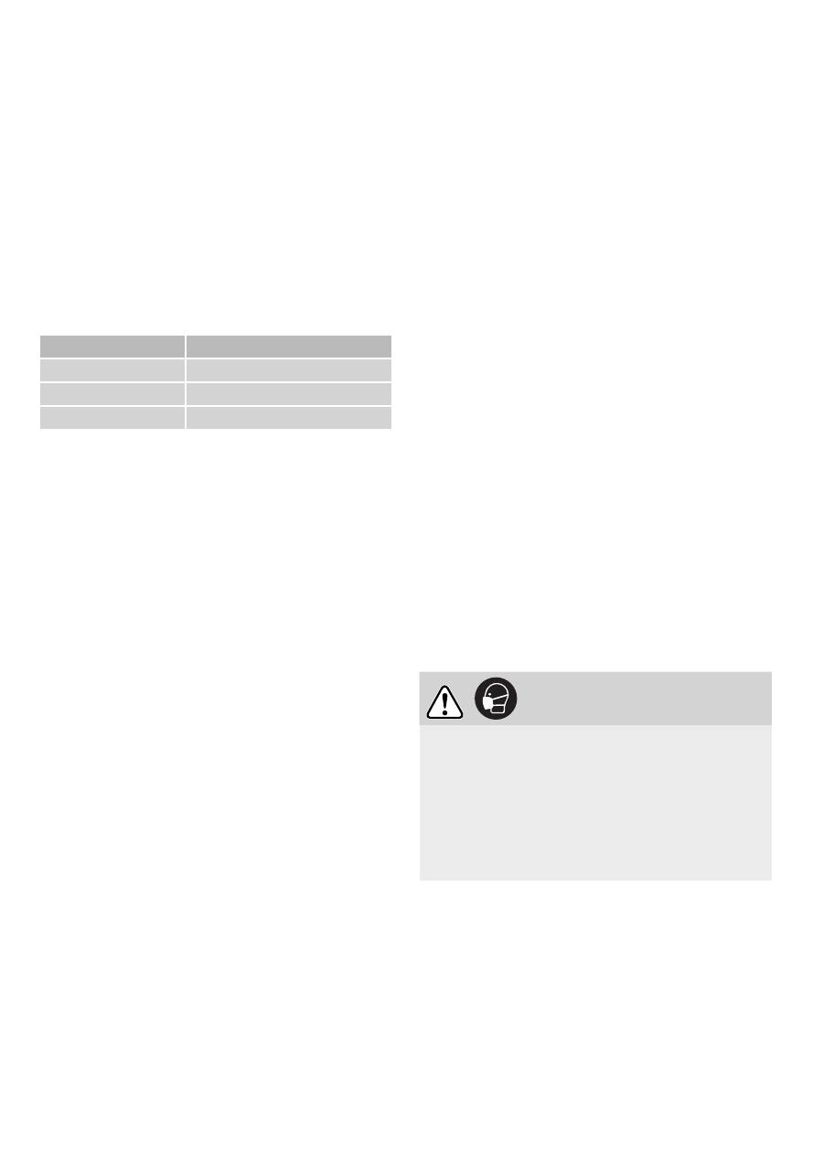
7.7 Dust extraction
CAUTION
Breathing in dust can damage the respiratory
passage.
Always connect the machine to a dust extractor.
Only work with the chip guard [10.2] in perfect
working order.
When performing work that generates dust,
always wear a dust mask.
A Festool dust extractor with an extractor hose
diameter of 36 mm or 27 mm (36 mm recom-
mended due to the reduced risk of clogging) can
be connected to the extractor connector [10.4]
The extractor connector [10.4] can be rotated
within the range indicated [10.3]. The extractor
connector on the extraction pipe will no longer be
secure if rotated outside of this range.
Оглавление
- VORSICHT
- WARNUNG
-
- VORSICHT
-
- WARNUNG
- CAUTION
- WARNING
-
- WARNING
-
- WARNING
- ATTENTION
- AVERTISSEMENT
-
- ATTENTION
-
- AVERTISSEMENT
- ATENCIÓN
- AVISO
-
- ATENCIÓN
-
- AVISO
- PRUDENZA
- AVVISO
-
- VOORZICHTIG
- WAARSCHUWING
-
- WAARSCHUWING
- VARNING
- VARNING!
-
- VARNING!
-
- VARO
- VAROITUS
-
- VAROITUS
-
- FORSIGTIG
- ADVARSEL
-
- ADVARSEL
-
- FORSIKTIG
- ADVARSEL!
-
- ADVARSEL!
-
- CUIDADO
- ADVERTÊNCIA
-
- ADVERTÊNCIA
- ВНИМАНИЕ
- ПРЕДУПРЕЖДЕНИЕ
-
- POZOR
- VÝSTRAHA
-
- VÝSTRAHA
-
- OSTROŻNIE
- OSTRZEŻENIE
-
