Festool C 12: инструкция
Раздел: Электроинструменты
Тип:
Инструкция к Festool C 12
Originalbedienungsanleitung/Ersatzteilliste
6 - 11
Original operating manual/Spare parts list
12 - 16
Notice d’utilisation d’origine/Liste de pièces de rechange
17 - 22
Manual de instrucciones original/Lista de piezas de repuesto
23 - 28
Istruzioni per l’uso originali/Elenco parti di ricambio
29 - 34
Originele gebruiksaanwijzing/Lijst met reserveonderdelen
35 - 40
Originalbruksanvisning/Reservdelslista
41 - 45
Alkuperäiset käyttöohjeet/Varaosaluettelo
46 - 50
Original brugsanvisning/Reservedelsliste
51 - 55
Originalbruksanvisning/Reservedelsliste
56 - 60
Manual de instruções original/Lista de peças sobresselentes
61 - 66
Оригинал
Руководства
по
эксплуатации
/
Перечень
запасных
частей
67 - 72
Originální návod k použití/Seznam náhradních díl
ů
73 - 77
Oryginalna instrukcja eksploatacji/Lista cz
ęś
ci zamiennych
78 - 83
468005_005
C 12


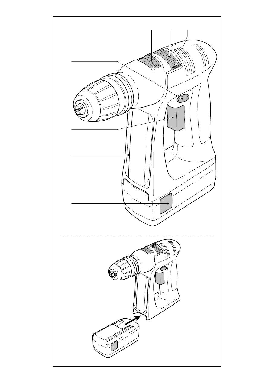
1.4 1.3 1.2 1.1
1
1.5 1.6 1.7
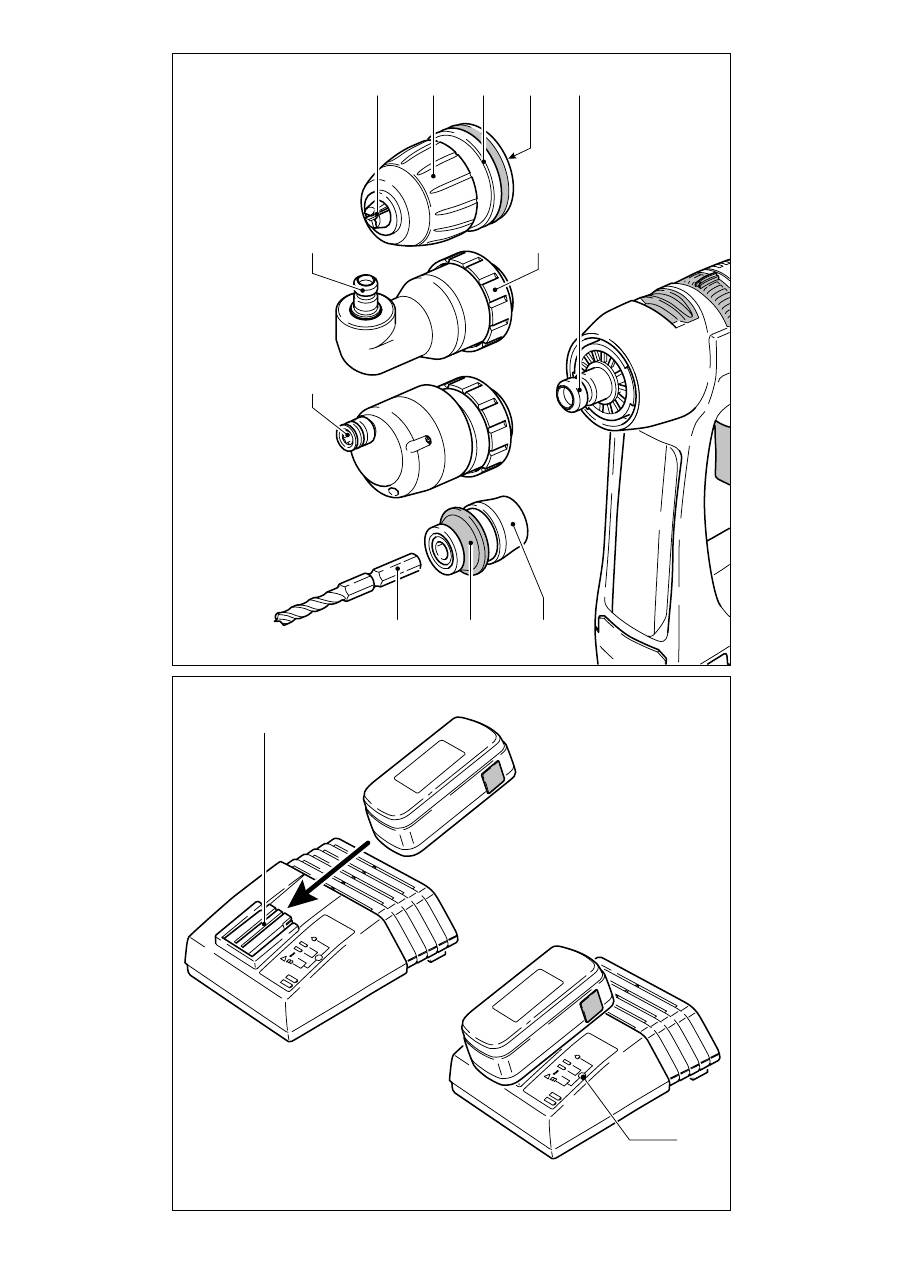
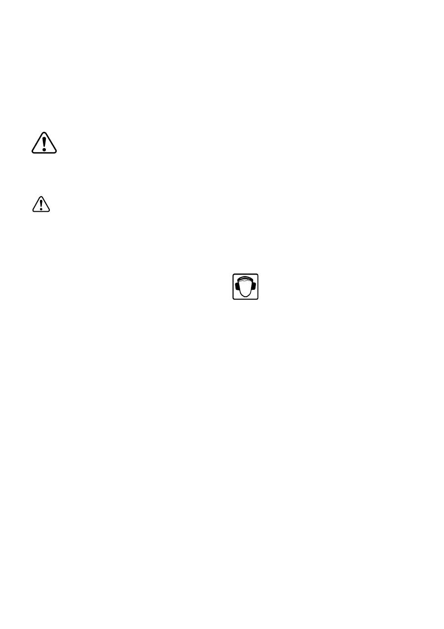
3.2
2
3
2.9 2.10 2.11 2.6 2.8 2.7 2.1 2.5 3.1 2.2 2.3 2.4 BF-FX DD-AS DD-ES WH-CE

6
Technische Daten
Akku-Bohrschrauber
C 12
Motorspannung
12 V
Leerlaufdrehzahl
1. Gang
0 - 450 min
-1
2. Gang
0 - 1500 min
-1
Drehmoment max.
weicher Schraubfall (Holz)
18 Nm
harter Schraubfall (Metall)
30 Nm
Drehmoment einstellbar
1. Gang
2 - 7 Nm
2. Gang
0,5 - 2,5 Nm
Bohrfutter-Spannbereich
1,5 - 13 mm
max. Bohrdurchmesser in Holz
25 mm
max. Bohrdurchmesser in Metall
14 mm
Werkzeugaufnahme in Bohrspindel
1/4“
Gewicht ohne Akku
0,96 kg
Ladegerät
LC 45
Netzspannung (Eingang)
230 -240 V~
Netzfrequenz
50/60 Hz
Ladespannung (Ausgang)
7,2 - 18 V=
Ladestrom
3 A
Schnellladung
max. 3 A
Erhaltungsladung pulsierend
ca. 0,06 A
Ladezeit für
NiCd 1,3 Ah
ca. 25 min
NiCd 2,4 Ah
ca. 50 min
NiMH 3,0 Ah
ca. 70 min
Akkupack
BPS 12 C NiCd
BPS 12 S NiCd
BPS 12 S NiMH
Bestellnummer
493348
492268
491821
Spannung
12 V
12 V
12 V
Kapazität
1,3 Ah
2,4 Ah
3,0 Ah
Ladetemperaturbereich
5 - 45 °C
5 - 45 °C
5 - 45 °C
Ladezustandsüberwachung
m i t t e l s N T C - W i d e r s t a n d
Gewicht
0,56 kg
0,73 kg
0,75 kg
Die angegebenen Abbildungen be
fi
nden sich am Anfang dieser Bedienungsanleitung.
7
1
Vor Inbetriebnahme beachten
1.1
Bestimmungsgemäße Verwen-
dung
Die Akku-Bohrschrauber sind zum Bohren
in Metall, Holz, Kunststoffen und ähnlichen
Materialien geeignet, sowie zum Festschrau-
ben und Einschrauben von Schrauben (bis
Durchmesser 6 mm in Holz).
Das Ladegerät LC 45 ist zum Au
fl
aden der
aufgeführten Akkupacks bestimmt.
Für Schäden und Unfälle bei nicht
bestimmungsgemäßem Gebrauch
haftet der Benutzer.
1.2 Sicherheitshinweise
a) Allgemeine
Sicherheitshinweise
Warnung!
Lesen Sie sämtliche Si-
cherheitshinweise und Anweisungen.
Fehler bei der Einhaltung der Warnhinwei-
se und Anweisungen können elektrischen
Schlag, Brand und/oder schwere Verletzun-
gen verursachen.
Bewahren Sie alle Sicherheitshinweise
und Anweisungen für die Zukunft auf.
Der in den Sicherheitshinweisen verwen-
dete Begriff „Elektrowerkzeug“ bezieht sich
auf netzbetriebene Elektrowerkzeuge (mit
Netzkabel) und auf akkubetriebene Elekt-
rowerkzeuge (ohne Netzkabel).
b) Maschinenspezifische
Sicher-
heitshinweise
- Ladegerät und Elektrowerkzeug sind nicht
dafür bestimmt, durch Personen (ein-
schließlich Kinder) mit eingeschränkten
physischen, sensorischen oder geistigen
Fähigkeiten oder mangels Erfahrung und/
oder mangels Wissen benutzt zu werden,
es sei denn, sie werden durch eine für ihre
Sicherheit zuständige Person beaufsichtigt
oder erhielten von ihr Anweisungen, wie
das Ladegerät bzw. Elektrowerkzeug zu
benutzen ist. Kinder sollten beaufsichtigt
werden, um sicherzustellen, dass sie nicht
mit dem Ladegerät oder Elektrowerkzeug
spielen.
- Fassen Sie die Maschine nur an isolierten
Griff
fl
ächen an, wenn Sie Arbeiten ausfüh-
ren, bei denen das Werkzeug verborgene
Stromleitungen treffen kann.
- Achten Sie beim Bohren in Wände auf
eventuell vorhandene Gas-, Strom- oder
Wasserleitungen.
- Öffnen Sie den Akkupack und das Lade-
gerät nicht. Im Inneren des Ladegerätes
steht auch nach der Trennung vom Netz
eine hohe Kondensatorspannung an.
- Achten Sie darauf, dass am Ladegerät in
die Aufnahmen der Akkupacks und durch
die Lüftungsschlitze keine Metallteile (z. B.
Metallspäne) ins Geräteinnere gelangen
(Kurzschlussgefahr).
- Schützen Sie den Akkupack vor Hitze z. B.
auch vor dauernder Sonneneinstrahlung
und Feuer. Es besteht Explosionsgefahr.
- Löschen Sie brennende LiIon-Akkupacks
nie mit Wasser, verwenden Sie Sand.
1.3
Lärm- und Vibrationsinformation
Akku-Bohrschrauber
Die nach EN 60745 ermittelten Werte betra-
gen typischerweise:
Schalldruckpegel 65
dB(A)
Schallleistungspegel 76
dB(A)
Messunsicherheitszuschlag
K = 3 dB
Beim Arbeiten kann der Geräuschpe-
gel 85 dB(A) überschreiten.
Gehörschutz
tragen!
Schwingungsemissionswert a
h
(Vektorsum-
me dreier Richtungen) und Unsicherheit K
ermittelt nach EN 60745:
Bohren in Metall
a
h
< 2,5 m/s²
K = 1,5 m/s²
Schrauben
a
h
< 2,5 m/s²
K = 1,5 m/s²
Die angegebenen Emissionswerte (Vibration,
Geräusch) wurden gemäß den Prüfbedin-
gungen in EN 60745 gemessen, und dienen
dem Maschinenvergleich. Sie eignen sich
auch für eine vorläu
fi
ge Einschätzung der
Vibrations- und Geräuschbelastung beim
Einsatz.
Die angegebenen Emissionswerte repräsen-
tieren die hauptsächlichen Anwendungen
des Elektrowerkzeugs. Wird jedoch das
Elektrowerkzeug für andere Anwendungen,
mit anderen Einsatzwerkzeugen oder unge-
nügend gewartet eingesetzt, kann dies die
Vibrations- und Geräuschbelastung über den
gesamten Arbeitszeitraum deutlich erhö-
hen. Für eine genaue Abschätzung während
einem vorgegebenen Arbeitszeitraum sind
auch die darin enthaltenen Leerlauf- und
Stillstandszeiten der Maschine zu beachten.

8
Dieses kann die Belastung über den gesam-
ten Arbeitszeitraum erheblich verringern.
1.4 Wandbefestigung LC 45
Das Ladegerät LC 45 besitzt an seiner Rück-
seite zwei Langlöcher, wodurch es mithilfe
von zwei Schrauben (z. B. Halbrund- oder
Flachkopfschraube mit Schaftdurchmesser
5 mm) an einer Wand aufgehängt werden
kann.
Schrauben Sie hierfür die beiden Schrauben
im Abstand von 96 mm so weit in die Wand,
dass der Schraubenkopf noch ca. 4 mm von
der Wand absteht.
2
Einstellungen an der Maschine
Vor jeglicher Einstellung, Instandhaltung
oder Instandsetzung Akkupack entfernen!
2.1 Akkupack wechseln
Akkupack abnehmen
Drücken Sie die beiden Tasten (1.1) und
nehmen Sie den Akkupack nach vorne hin
ab.
Akkupack einsetzen
Schieben Sie den Akkupack bis zum Einras-
ten auf die Halterung an der Griffunterseite
(siehe Bild 1).
2.2 Umschalten der Drehrichtung
Der Schaltknopf (1.4) ist zur Bestimmung
der Drehrichtung.
Knopf von rechts nach links gedrückt =
Rechtslauf;
Knopf von links nach rechts gedrückt =
Linkslauf;
Knopf in Mittelstellung =
Einschaltsper-
re.
2.3 Getriebeumschaltung
Nur im Stillstand schalten!
Mit Schaltschieber (1.5) wird das Getriebe
geschaltet.
1. Gang
Schaltschieber nach vorn - Ziffer 1 ist sicht-
bar.
2. Gang
Schaltschieber nach hinten - Ziffer 2 ist
sichtbar.
2.4 Drehmomenteinstellung
Durch Verdrehen des Stellrings (1.6) kann
das Drehmoment eingestellt werden. Die
Markierung (1.7) zeigt den eingestellten
Zustand an. Die Maschine schaltet bei Er-
reichen des eingestellten Drehmomentes
ab. Die Maschine läuft erst wieder, wenn der
EIN-/AUS-Schalter (1.3) losgelassen und
erneut gedrückt wird.
Bohren
Markierung zeigt auf Bohrersymbol = maxi-
males Drehmoment.
Schrauben
Drehmoment entsprechend Einstellung:
Stellung auf 1 = kleines Drehmoment
Stellung auf 20 = hohes Drehmoment
3 Werkzeugaufnahme,
Vorsatzag-
gregate
3.1 Bohrfutter
BF-FX
Das Bohrfutter dient zum Einspannen von
Bohrern und Bits.
a) Bohrfutter
montieren/demontie-
ren
Montage
- Setzen Sie das Bohrfutter auf die Bohrspin-
del (2.5) auf und verdrehen Sie es so weit,
bis der Sechskantstift (2.4) des Bohrfutters
in die Innensechskantaufnahme der Bohr-
spindel einrastet.
- Ziehen Sie den Entriegelungsring (2.3)
nach vorne, drücken Sie das Bohrfutter
bis zum Anschlag auf die Bohrspindel und
lassen Sie den Entriegelungsring los.
Demontage
- Ziehen Sie den Entriegelungsring nach
vorne und nehmen Sie das Bohrfutter ab.
b) Werkzeug
wechseln
- Drehen Sie die Spannhülse (2.2) gegen den
Uhrzeigersinn, um die Spannbacken (2.1)
zu öffnen (
Hinweis:
Bei ausgeschalteter
Maschine ist die Spindel automatisch ar-
retiert).
- Setzen Sie das Werkzeug in das Bohrfutter
ein.
- Spannen Sie das Werkzeug fest, indem Sie
die Spannhülse im Uhrzeigersinn drehen.
Achten Sie immer darauf, dass das Werk-
zeug zentrisch im Bohrfutter gespannt
ist.

9
3.2 Winkelvorsatz DD-AS
Der Winkelvorsatz ermöglicht ein Arbeiten
(Bohren, Schrauben) senkrecht zur Längs-
achse der Maschine.
a) Winkelvorsatz
montieren/de-
montieren
Montage
- Setzen Sie den Winkelvorsatz auf die Bohr-
spindel auf und verdrehen Sie ihn so weit,
bis er in der gewünschten Position einrastet
(
Hinweis:
Der Winkelvorsatz lässt sich in
16 verschiedenen Winkelstellungen ein-
rasten).
- Verriegeln Sie den Winkelvorsatz, indem
Sie den Befestigungsring (2.7) im Uhrzei-
gersinn fest drehen.
Demontage
- Drehen Sie den Befestigungsring gegen
den Uhrzeigersinn bis zum Anschlag und
nehmen Sie den Winkelvorsatz ab.
b)
Bohrfutter auf Winkelvorsatz
montieren/demontieren
Das Bohrfutter wird in gleicher Weise auf die
Welle (2.6) des Winkelvorsatzes befestigt
wie auf die Bohrspindel der Maschine.
3.3 Exzentervorsatz DD-ES
Der Exzentervorsatz dient zur Aufnahme
von Bits. Er ermöglicht ein Rand nahes
Schrauben.
a) Exzentervorsatz
montieren/de-
montieren
Die Montage/Demontage des Exzentervor-
satzes erfolgt in gleicher Weise wie die des
Winkelvorsatzes (siehe Kapitel 3.2).
b) Werkzeug
wechseln
- Ziehen Sie den Entriegelungsring (2.8)
zurück und entnehmen Sie das Werkzeug
bzw. setzen Sie ein Werkzeug ein.
3.4
Werkzeughalter
CENTROTEC
WH-CE
Der Werkzeughalter CENTROTEC ermöglicht
einen schnellen Wechsel von Werkzeugen
mit CENTROTEC-Schaft.
Spannen Sie CENTROTEC Werkzeuge
nicht am runden Schaftteil in einem
herkömmlichen Bohrfutter, damit der
Schaft nicht beschädigt wird.
Verletzungsgefahr!
Handhaben Sie
das Werkzeug mit seinen scharfen
Schneiden beim Werkzeugwechsel
mit besonderer Vorsicht und tragen
Sie ggf. Schutzhandschuhe.
a) CENTROTEC
montieren/demon-
tieren
Montage
- Ziehen Sie den Entriegelungsring (2.11)
nach vorne, setzen Sie den Werkzeughalter
bis zum Anschlag auf die Bohrspindel (2.5)
und lassen Sie den Entriegelungsring los.
Demontage
- Ziehen Sie den Entriegelungsring nach
vorne und nehmen Sie den Werkzeughalter
ab.
b) Werkzeug
wechseln
- Ziehen Sie zum Einsetzen bzw. Entnehmen
eines Werkzeuges mit CENTROTEC-Schaft
den grünen Entriegelungsring (2.10) zu-
rück. Verdrehen Sie beim Einsetzen das
Werkzeug bis dessen Sechskantschaft (2.9)
in die Sechskantaufnahme der Bohrspindel
einrastet und schieben Sie das Werkzeug
bis zum Anschlag in den Werkzeughalter.
3.5 Werkzeugaufnahme in der Bohr-
spindel
Damit die Maschine leichter und kürzer wird,
können Bits direkt in der Innensechskant-
aufnahme der Bohrspindel (2.5) eingesetzt
werden.
4
Akkupack laden
Zum Laden ist der Akkupack bis zum An-
schlag auf die Halterung (3.1) des Lade-
gerätes zu schieben. In entgegengesetzter
Richtung kann der geladene Akkupack dem
Ladegerät entnommen werden. Der ein-
gesetzte Akkutyp (NiCd oder NiMH) wird
automatisch erkannt. Der Ladevorgang wird
mittels Mikroprozessor gesteuert. Wird ein
warmer NiMH-Akkupack (>37 °C) einge-
setzt, wird nur mit reduziertem Ladestrom
geladen. In diesem Fall verlängert sich die
Ladezeit.
Die LED (3.2) zeigt den jeweiligen Be-
triebszustand des Ladegerätes an.
LED gelb - Dauerlicht:
Ladegerät ist betriebsbereit.
LED grün - Blinklicht:
Akkupack wird geladen.
LED grün - Dauerlicht:
Akkupack ist aufgeladen, Erhaltungsladung
läuft.
LED rot - Blinklicht:
allgemeine Fehleranzeige, z. B.: keine
10
vollständige Kontaktierung, Kurzschluss,
Akkupack defekt.
LED rot - Dauerlicht:
Akkutemperatur außerhalb zulässiger
Grenzwerte.
Beachten Sie unbedingt die Hin-
weise im Kapitel „Arbeitshinwei-
se - Wartung - P
fl
ege“.
5
Arbeiten mit der Maschine
5.1 Inbetriebnahme
Einschalten durch Drücken der Schaltertaste
(1.3). Je nach Druck auf die Schaltertaste,
ist die Drehzahl stufenlos steuerbar. Aus-
schalten durch Loslassen der Schaltertaste
(1.3). Nach dem Loslassen der Schalter-
taste wird die Arbeitsspindel (Bohrfutter)
abgebremst und damit ein Nachlaufen des
Werkzeugs verhindert.
5.2 Bit-Depot
In die Bit-Depots (1.2) mit Magnethalter
lassen sich mehrere Bits oder Bitverlänge-
rungen einlegen.
5.3 Warnsignal
Bei folgenden Betriebszuständen ertönt von
der Maschine ein akustisches Warnsignal und
die Maschine schaltet ab:
Piepton in regelmäßigen Abständen
- Akku leer
Dreifacher Piepton in regelmäßigen
Abständen
- Belastung (Drehmoment) zu hoch
- Maschine zu warm.
6
Arbeitshinweise - Wartung -
P
fl
ege
Bitte beachten Sie die nachfol-
genden Hinweise. Ansonsten
besteht die Gefahr einer Schädi-
gung der Maschine, des Ladege-
rätes oder des Akkupacks.
- Reparaturen dürfen nur vom Fachmann
ausgeführt werden. Beim Ladegerät LC 45
steht auch nach der Trennung vom Netz am
Leistungsteil im Innern des Gerätes eine
hohe Kondensatorspannung an.
- Lüftungsöffnungen am Elektrowerkzeug
und am Ladegerät sauber halten, damit
Luftzirkulation zur Kühlung gewährleistet
ist.
- Am Ladegerät dürfen in die Aufnahmen der
Akkupacks und durch die Lüftungsschlitze
hindurch ins Geräteinnere keine Metallteile
(z. B. Metallspäne) gelangen (Kurzschluss-
gefahr).
- Verwenden Sie nur originale Festool-Akku-
packs. Verwenden Sie keine gebrauchten
und wieder aufbereiteten Akkupacks. Für
Schäden bei Verwendung von nicht origi-
nalen Festool-Akkupacks haftet der Benut-
zer.
- Anschlusskontakte am Elektrowerkzeug,
Ladegerät und Akkupack sauber halten.
- Durch die Aufbewahrung des Akkupacks
im betriebsbereiten Ladegerät wird der
Akkupack durch ständige Erhaltungsladung
im aufgeladenen Zustand gehalten.
- Leere Akkupacks nicht länger als ca. 1 Mo-
nat im Ladegerät stecken lassen, wenn das
Ladegerät vom Netz getrennt ist (Gefahr
der Tiefentladung).
- Ein neuer, oder längere Zeit nicht ge-
brauchter, Akkupack erreicht erst nach
ca. 5 Lade- und Entladezyklen seine volle
Kapazität.
- Akkupacks sollten vor dem erneuten Au
fl
a-
den möglichst vollständig entladen werden.
Wiederholter Start des Ladevorgangs bei
gela-denem Akku verringert dessen Le-
bensdauer.
- Eine wesentlich verkürzte Betriebszeit je
Au
fl
adung zeigt an, dass der Akkupack ver-
braucht ist und durch einen neuen ersetzt
werden muss.
- NiCd-Akkupacks, die längere Zeit nicht
benutzt werden, sollten im entladenen
Zustand aufbewahrt werden.
Besondere Hinweise für NiMH-Akku-
packs:
- Bei Umgebungstemperatur unter 0 °C oder
über 45 °C nimmt die Leistung von NiMH-
Akkupacks spürbar ab.
- Maschine nicht überlasten (Maschine nicht
so stark beanspruchen, dass diese zum
Stillstand kommt).
- NiMH-Akkupacks auch bei Nichtbenutzung
ca. alle 4 Monaten erneut au
fl
aden, um
deren volle Kapazität zu erhalten.
- NiMH-Akkupacks sollten nach ca. jedem
10. Ladevorgang nach der Schnellladung
noch für eine Stunde im Ladegerät verblei-
ben, um mögliche Kapazitätsunterschiede
zwischen den Zellen auszugleichen.

11
- NiMH-Akkupacks aufgrund der Selbstentla-
dung vorzugsweise bei Umgebungstempe-
raturen zwischen 0 °C und 25 °C lagern.
7
Recycling von Akkupacks
Werfen Sie den verbrauchten
Akkupack nicht in den Haus-
müll!
Geben Sie verbrauchte oder defekte Akku-
packs über den Fachhandel, den Festool-
Kundendienst oder öffentlich vorgeschrie-
bene Entsorgungseinrichtungen zurück. Die
Akkupacks werden so einem geordneten
Recycling zugeführt.
8 Gewährleistung
Für unsere Geräte leisten wir auf Materi-
al- oder Fertigungsfehler Gewährleistung
gemäß den länderspezi
fi
schen gesetzlichen
Bestimmungen, mindestens jedoch 12 Mo-
nate. Innerhalb der Staaten der EU beträgt
die Gewährleistungszeit 24 Monate (Nach-
weis durch Rechnung oder Lieferschein).
Schäden, die insbesondere auf natürliche
Abnützung/Verschleiß, Überlastung, un-
sachgemäße Behandlung bzw. durch den
Verwender verschuldete Schäden oder
sonstige Verwendung entgegen der Bedie-
nungsanleitung zurückzuführen sind oder
beim Kauf bekannt waren, bleiben von der
Gewährleistung ausgeschlossen. Eben-
so ausgeschlossen bleiben Schäden, die
auf die Verwendung von nicht-originalem
Festool Zubehör und Verbrauchmaterial
(z. B. Schleifteller) zurückzuführen sind.
Beanstandungen können nur anerkannt
werden, wenn das Gerät unzerlegt an den
Lieferanten oder an eine autorisierte Festool-
Kundendienstwerkstätte zurückgesendet
wird. Bewahren Sie Bedienungsanleitung,
Sicherheitshinweise, Ersatzteilliste und Kauf-
beleg gut auf. Im übrigen gelten die jeweils
aktuellen Gewährleistungsbedingungen des
Herstellers.
Anmerkung
Aufgrund der ständigen Forschungs- und
Entwicklungsarbeiten sind Änderungen der
hierin gemachten technischen Angaben
vorbehalten.
9 EG-Konformitätserklärung
Akku-Bohr-
schrauber
Serien-Nr.
C12
490454
Jahr der CE-Kennzeichnung: 2005
Wir erklären in alleiniger Verantwortung,
dass dieses Produkt mit den folgenden Nor-
men oder normativen Dokumenten überein-
stimmt:
EN 60745-1, EN 60745-2-1, EN 60745-2-2,
EN 55014-1 gemäß den Bestimmungen der
Richtlinien 98/37/EG (bis 28. Dez. 2009),
2006/42/EG (ab 29. Dez. 2009), 2004/108/
EG.
Ladegerät
Serien-Nr.
LC 45
491573, 491815
Jahr der CE-Kennzeichnung: 2003
Wir erklären in alleiniger Verantwortung,
dass dieses Produkt mit den folgenden Nor-
men oder normativen Dokumenten über-
einstimmt: EN 60335-1, EN 60335-2-29,
EN 61000-3-2, EN 61000-3-3, EN 61204-3
gemäß den Bestimmungen der Richtlinien
2004/108/EG, 2006/95/EG.
Dr. Johannes Steimel
Leiter Forschung und Entwicklung
Festool GmbH, Wendlingen

12
Technical data
Cordless drill/screwdriver
C 12
Motor voltage
12 V
Idle-running speed
1. Speed
0 - 450 rpm
2. Speed
0 - 1500 rpm
Max torque
Soft boring (wood)
18 Nm
Hard boring (metal)
30 Nm
Adjustable torque
1. Speed
2 - 7 Nm
2. Speed
0.5 - 2.5 Nm
Chuck capacity
1.5 - 13 mm
Max. drill diameter for wood
25 mm
Max. drill diameter for metal
14 mm
Tool
fi
tting in chuck
1/4“
Weight without battery pack
0.96 kg
Charger
LC 45
Supply voltage (input)
230 -240 V~
Line frequency
50/60 Hz
Charging voltage (output)
7,2 - 18 V=
Charging current
3 A
Quick charge
max. 3 A
Compensation charge pulsating
app. 0.06 A
Charging time
NiCd 1.3 Ah
app. 25 min
NiCd 2.4 Ah
app. 50 min
NiMH 3.0 Ah
app. 70 min
Battery pack
BPS 12 C NiCd
BPS 12 S NiCd
BPS 12 S NiMH
Order number
493348
492268
491821
Voltage
12 V
12 V
12 V
Capacity
1.3 Ah
2.4 Ah
3.0 Ah
Temp. range for charging
5 - 45 °C
5 - 45 °C
5 - 45 °C
Temperature monitoring
u s i n g N T C r e s i s t o r
Weight
0.56 kg
0.73 kg
0.75 kg
The speci
fi
ed illustrations can be found at the beginning of the operating instructions.
1
Before starting up, please ob-
serve the following
1.1 Intended use
Cordless drills are suitable for drilling metal,
wood, plastics and similar materials, as well
as tightening and screwing in screws (into
wood, up to a diameter of 6 mm).
The LC 45 battery charger is designed for
recharging the battery pack listed.
The user is liable for damage and in-
jury resulting from incorrect usage!
1.2 Safety instructions
a)
General Safety Rules
WARNING! Read all safety warn-
ings and all instructions.
Failure to
follow the warnings and instructions
may result in electric shock,
fi
re and/or se-
rious injury.
Save all warnings and instructions for
future reference.
The term „power tool“ in the warnings refers
to your mains-operated (corded) power tool
or battery-operated (cordless) power tool.

13
b)
Machine-related safety instruc-
tions
- Charger and power tool are not intended
for use by persons (including children) with
limited physical, sensory or mental ability
or without suf
fi
cient experience and/or
knowledge, unless they are supervised by a
person responsible for their safety or have
been instructed on how the charger or pow-
er tool is to be used. Children should always
be supervised to ensure that they do not
play with the charger or the power tools.
- Always hold the machine by the insulated
handles if there is a possibility of drilling
into hidden power cables.
- Take care when drilling into walls as there is
a danger of rupturing concealed gas/water
pipes or cutting through power cables.
- Do not open the battery pack or the
charger. Even after disconnection from the
mains, there is still a high capacitor voltage
inside the charger.
- Make sure that metal objects (such as
metal chips) do not collect in the battery
pack retaining slots or enter the machine
through the air vent slits (danger of short
circuit).
- Protect the battery pack from excessive
heat or constant heat sources such as
sunlight or naked
fl
ames. There is a risk
of explosion.
- Never use water to extinguish burning LiIon
battery packs, always use sand.
1.3 Noise and vibration information
Cordless drill/screwdriver
The typical values determined in accordance
with EN 60745 are:
Sound pressure level
65 dB(A)
Sound-power level
76 dB(A)
Measuring uncertainty allowance K = 3 dB
The noise level can exceed 85 dB(A)
during operation.
Wear ear protection!
Vibration emission value a
h
(vector sum for
three directions) and uncertainty K meas-
ured in accordance with EN 60745:
Drilling in metal
a
h
< 2,5 m/s²
K = 1,5 m/s²
Screws
a
h
< 2,5 m/s²
K = 1,5 m/s²
The emission values speci
fi
ed (vibration,
noise) were measured in accordance with
the test conditions stipulated in EN 60745
and are intended for machine comparisons.
They are also used for making preliminary
estimates regarding vibration and noise
loads during operation.
The emission values speci
fi
ed refer to the
main applications for which the power tool
is used. If the electric power tool is used
for other applications, with other tools or is
not maintained suf
fi
ciently prior to opera-
tion, however, the vibration and noise load
may be higher when the tool is used. Take
into account any machine idling times and
downtimes to estimate these values more
accurately for a speci
fi
ed time period. This
may signi
fi
cantly reduce the load during the
machine operating period.
1.4 Wall mounting LC 45
The charger LC 45 has two longitudinal slots
on its rear by which it can be suspended on
walls using two screws (e.g. button-headed
or
fl
at head screw with a shaft diameter of
5 mm). Screw both screws into the wall
96 mm apart until the screwhead is protrud-
ing from the wall by approx. 4 mm.
2
Machine settings
Remove the battery pack before any adjust-
ments, maintenance or repair is carried out!
2.1 Exchanging the battery pack
Removing battery pack
Press the two buttons (1.1) and slide the
battery pack forwards to remove.
Inserting battery pack
Slide the battery pack into the holder on the
underside of the handle until it latches into
place (see Fig. 1).
2.2 To change the direction of rotation
The selector button (1.4) determines the
direction of rotation.
Turn button from right to left =
clockwise
rotation.
Turn button from left to right =
anticlockwise rotation.
Selector button in
central position =
circuit interlock.
2.3 Shifting speeds
Change only when completely
stopped!
Using the shift lever (1.5), the speed can
be changed.

14
1. Speed:
Lever forward - Figure 1 is visible.
2. Speed:
Lever backwards - Figure 2 is
visible.
2.4 Torque adjustment
By turning the adjustment ring (1.6) the
required torque can be adjusted. The arrow
(1.7) aligns with the adjusted state.
The machine switches off when the set torque
has been reached. The machine does not
start running again until the ON/OFF switch
(1.3) is released and then pressed again.
Drilling
Drilling symbol on adjustment ring aligns
with the arrow = maximum torque.
Screws
Torque corresponding to setting:
Position 1 = low torque
Position 20 = high torque
3
Tool holding
fi
xture, attachments
3.1 Chuck BF-FX
The chuck is used to clamp drills and bits.
a)
Fitting/removing the chuck
Fitting
- Place the chuck on the drill spindle (2.5)
and twist until the hexagon key (2.4) of
the chuck latches into the hexagon socket
of the drill spindle.
- Pull the unlocking ring (2.3) forwards,
press the chuck onto the drill spindle up to
the stop and release the unlocking ring.
Removal
- Pull the unlocking ring forwards and re-
move the chuck.
b) Changing
tools
- Turn the clamping sleeve (2.2) anti-clock-
wise to open the clamping jaws (2.1)
(
Note:
the spindle is automatically locked
when the machine is switched off).
- Insert the tool into the chuck.
- Clamp the tool by turning the clamp-
ing sleeve clockwise. Always make sure
that the tool is clamped centrally in the
chuck.
3.2 Angle attachment DD-AS
The angle attachment permits work (drilling,
screwing) vertical to the machine’s longitu-
dinal axis.
a)
Fitting/removing the angle at-
tachment
Fitting
- Place the angle attachment on the drill
spindle and turn until it catches in the
desired position (
Note:
The angle attach-
ment can be
fi
tted in 16 different angle
settings).
- Lock the angle attachment by turning the
fastening ring (2.7) tightly clockwise.
Removal
- Turn the fastening ring anti-clockwise up
to the stop and remove the angel attach-
ment.
b)
Fitting/removal of chuck on an-
gle attachment
The chuck is
fi
tted on the shaft (2.6) of the
angle attachment in the same way as on the
drill spindle of the machine.
3.3
Eccentric attachment DD-ES
The eccentric attachment is used to hold
bits. It allows screwing close to edges.
a)
Fitting/removing the eccentric
attachment
The eccentric attachment is
fi
tted/removed
in the same was as the angle attachment
(see Chapter 3.2).
b)
Changing tools
- Pull the unlocking ring (2.8) back and re-
move the tool and/or insert the new tool.
3.4
CENTROTEC WH-CE toolholder
The CENTROTEC toolholder enables rapid
changes of tools with CENTROTEC shafts.
Do not
fi
t CENTROTEC tools at the
round shaft section in a conventional
chuck to prevent damage to the
shaft.
Danger of injury!
When changing
tools, handle the tool and its sharp
cutters with special care and wear
protective gloves, if necessary.
a) Fitting/removing
CENTROTEC
Fitting
- Pull the release ring (2.11) forwards, place
the toolholder as far as it will go on the drill
spindle (2.5) and let go of the release ring.
Removal
- Pull the release ring forwards and take off
the toolholder.

15
b) Changing
tools
- To insert or remove a tool with CENTROTEC
shaft, pull the green release ring (2.10)
back. On inserting the tool, turn it until its
hex shank arbour (2.9) locks in place in the
hexagonal shank of the drill spindle, and
push the tool into the toolholder as far as
it will go.
3.5 Tool holding
fi
xture in the drill
spindle
Bits can be
fi
tted directly in the hexagon
socket holder of the drill spindle (2.5) to
make the machine lighter and shorter.
4
Charge battery pack
To load the battery pack, push it into the
holder (3.1) on the charger up to the stop.
Perform this in reverse to remove the battery
pack from the charger. The battery type used
(NiCd or NiMH) is detected automatically.
Charging is controlled by a microprocessor.
If a warm NiMH battery pack (>37° C) is
inserted, charging will only be carried out
at a lower charge current. In this case, the
charging time is extended.
The LED (3.2) indicates the respective
charging state of the charger.
LED yellow – steady:
Charger is ready for use.
LED green –
fl
ashing:
Battery pack being charged.
LED green – steady:
Battery pack fully charged, conservation
charge on.
LED red –
fl
ashing:
General malfunction, e. g. full contact not
being made, short-circuit, battery pack
faulty.
LED red – steady:
Temperature of battery pack is outside
permissible limit.
It is essential that you read
the instructions in the Chapter
„Working instructions - Mainte-
nance - Care“.
5
Working with the machine
5.1 Initial operation
Turn on by pressing button (1.3). Depending
on the pressure exerted on the button, the
adjustment of running speed can be varied
in
fi
nitely. Turn off by releasing the button
(1.3).
After releasing the button, the chuck is
stopped and therefore, after-running of the
equipment is prevented.
5.2
Bit storage well
You can insert several bits or bit extensions
into the bit magazine (1.2) with magnetic
holder.
5.3 Warning signal
With the following operational statuses, the
machine sounds an acoustic warning signal
and switches off:
Peep at regular intervals
- Battery empty
Triple peep at regular intervals
- Excessive load (torque)
- Machine too warm.
6
lnstructions on application -
maintenance - care
Please pay attention to the fol-
lowing instructions. Otherwise
there is a risk of damage to the
tool, charger or battery pack.
- Repairs may only be performed by author-
ised technicians. LC 45 charging device:
Even after disconnection from the mains,
there is still a high capacitor voltage on the
power output component on the inside of
the device.
- Keep the air vents of the electronic equip-
ment and the charger clean to guarantee
the air circulation for cooling.
- No metal objects (metal chips) should
enter the charger at the contact points as
well as through the cooling slits into the
equipment (danger of short circuit).
- Only use original Festool battery packs.
Do not use spent and recycled battery
packs. The user shall be liable for dam-
ages if Festool original battery packs are
not used.
- Keep the connection contacts of electronic
equipment, charger and battery pack
clean.
- By keeping the battery pack in a ready for
use charger, the battery pack will be kept
in a state of readiness by
fl
oat charging
conservation.
- Do not keep discharged battery pack
(maximum one month) attached to charger
whenever charger is detached from the

16
power supply (danger of deep discharg-
ing).
- A new battery pack or a battery pack not
used for a longer period of time reaches
it full capacity after about 5 charging and
discharging cycles.
- Battery packs should, before charging, be
fully discharged if possible.
Continuous starting of the charging process
shortens the lifespan of the batteries.
- A considerably reduced time of operation
per charging shows that the battery pack is
used up an should be replaced by a new one.
- NiCd battery packs that are not used for
longer periods should be stored in a dis-
charged state.
Special instructions for NiMH battery
packs:
- The output of NiMH battery packs drops
noticeably at ambient temperatures below
0° C or above 45° C.
- Do not overload the tool (do not load the
tool excessively so that it comes to a stand-
still).
- Even if NiMH battery packs are not used,
recharge them approx. every 4 months so
that they retain their full capacity.
- NiMH battery packs should be left for 60
min. in the charger after every 10th fast
charge to compensate any differences in
capacity between the cells.
- Because NiMH battery packs discharge
auto-matically, store them preferably at
ambient temperatures of between 0° C and
25° C.
7
Recycling battery packs
Never throw spent battery packs
into domestic waste containers!
Return spent or defective battery packs
to dealers, the Festool after-sales service
department or approved waste disposal fa-
cilities. This ensures that they are correctly
recycled.
8
Warranty
Our equipment is under warranty for at
least 12 months with regard to material or
production faults in accordance with national
legislation. In the EU countries, the warranty
period is 24 months (an invoice or delivery
note is required as proof of purchase). Dam-
age resulting from, in particular, normal wear
and tear, o-verloading, improper handling, or
caused by the user or other damage caused
by not following the operating instructions,
or any fault acknowledged at the time of
purchase, is not covered by the warranty.
Damage caused by the use of non-original
accessories and consumable material (e.g.
sanding pads) is also excluded. Complaints
will only be acknowledged if the equipment
has not been dismantled before being sent
back to the suppliers or to an authorised
Festool customer support workshop. Store
the operating instructions, safety notes,
spare parts list and proof of purchase in a
safe place. In addition, the manufacturer‘s
current warranty conditions apply.
Note
We reserve the right to make changes to
the technical data contained in this infor-
mation as a result of ongoing research and
development work.
9
EU Declaration of Conformity
Cordless drill/
screwdriver
Serial no.
C12
490454
Year of CE mark: 2005
We declare under sole responsibility that this
product complies with the following norms
or normative documents: EN 60745-1, EN
60745-2-1, EN 60745-2-2, EN 55014-1
in accordance with the regulations stipu-
lated in Directive 98/37/EC (until 28 Dec.
2009), 2006/42/EC (from 29 Dec. 2009),
2004/108/EC.
Charger
Serial no.
LC 45
491573, 491815
Year of CE mark: 2003
We declare under sole responsibility that this
product complies with the following norms
or normative documents: EN 60335-1, EN
60335-2-29, EN 61000-3-2, EN 61000-3-3,
EN 61204-3 in accordance with the regula-
tions stipulated in Directive 2004/108/EC,
2006/95/EC.
Dr. Johannes Steimel
Head of research and development
Festool GmbH, Wendlingen, Germany

17
Données techniques
Perceuses-visseuses à accumulateur
C 12
Tension du moteur
12 V
Vitesse à vide
1ère vitesse 0 - 450 tr/min
2ème vitesse 0 - 1500 tr/min
Couple de rotation max.
Cas de vissage dans un matériau tendre (bois)
18 Nm
Cas de vissage dans un matériau dur (métal)
30 Nm
Réglage de couple
1ère vitesse
2 - 7 Nm
2ème vitesse
0,5 - 2,5 Nm
Capacité mandrin
1,5 - 13 mm
Maxi capacité de perçage dans du bois
25 mm
Maxi capacité de perçage dans du métal
14 mm
Raccordement d’outil dans la broche de perçag
1/4“
Poids sans accumulateur
0,96 kg
Chargeur
LC 45
Tension secteur (entrée)
230 -240 V~
Fréquence secteur
50/60 Hz
Tension de charge (sortie)
7,2 - 18 V=
Courant de charge
3 A
Charge rapide
3 A max.
Charge de maintien à impulsions,
environ 0,06 A
Durée de charge pour
NiCd 1,3 Ah
25 min. env.
NiCd 2,4 Ah
50 min. env.
NiMH 3,0 Ah
70 min. env.
Accumulateur
BPS 12 C NiCd BPS 12 S NiCd BPS 12 S NiMH
Référence
493348
492268
491821
Tension
12 V
12 V
12 V
Capacité
1,3 Ah
2,4 Ah
3,0 Ah
Plage de température de charge
5 - 45 °C
5 - 45 °C
5 - 45 °C
Contrôle de la température
a u m o y e n d ’ u n r h é o s t a t N T C
Poids
0,56 kg
0,73 kg
0,75 kg
Les illustrations indiquées se trouvent au début du mode d’emploi.
18
1
A respecter avant la mise en ser-
vice
1.1 Utilisation
conforme
La perceuse-visseuse sans
fi
l est adaptée au
perçage du métal, du bois, des plastiques et
matériaux similaires, ainsi qu’au vissage (vis
jusqu’à un diamètre de 6 mm dans le bois).
Le chargeur LC 45 convient au chargement
de la batterie utilisée.
L’utilisateur est responsable des
dégâts ou accidents qu’il peut pro-
voquer en ne respectant pas les
dispositions de sécurité.
1.2
Informations de sécurité
a)
Indications générales de sécurité
ATTENTION ! Lire toutes les consi-
gnes de sécurité et indications.
Le
non-respect des avertissements et
instructions indiqués ci-après peut entraîner
un choc électrique, un incendie et/ou de
graves blessures.
Conservez toutes les consignes de sé-
curité et notices pour une référence
future.
Le terme « outil » dans les avertissements
fait reference à votre outil électrique ali-
menté par le secteur (avec cordon d’ali-
mentation) ou votre outil fonctionnant sur
batterie (sans cordon d’alimentation).
b)
Consignes de sécurité spéci
fi
ques
à la machine
- Ce chargeur et cet outil électrique ne sont
pas appropriés pour une utilisation par
des personnes (y compris enfants) ayant
des facultés physiques, sensorielles ou
intellectuelles limitées ou par manque
d‘expérience et/ou manque de connais-
sances, à moins d‘être sous la surveillance
d‘une personne responsable pour leur sé-
curité ou d‘avoir eu de cette personne des
instructions sur l‘utilisation du chargeur ou
de l‘outil électrique. Les enfants devraient
rester sous surveillance, a
fi
n de s‘assurer
qu‘ils ne jouent pas avec le chargeur ou
l‘outil électrique.
- Tenez la machine uniquement au niveau
des surfaces isolées de la poignée lorsque
vous effectuez des travaux au cours des-
quels l'outil risque de toucher des câbles
électriques cachés.
- Lors du perçage dans le murs, faites atten-
tion à d'éventuelles conduites de gaz, de
courant électrique ou d'eau.
- N'ouvrez pas la batterie, ni le chargeur.
La tension au condensateur à l'intérieur
du chargeur reste élevée même après le
débranchement du réseau.
- Assurez-vous qu'aucune particule métal-
lique (p. ex. copeaux métalliques) ne
puisse parvenir dans le chargeur au niveau
du logement de la batterie, ni à travers
les fentes d'aération (risque de court-cir-
cuit).
- Protégez la batterie contre la chaleur, p.
ex. également contre les rayons de sol-
eil permanents ou le feu. Il y a risque
d'explosion.
- N'utilisez en aucun cas de l'eau pour
éteindre une batterie "Li-ion" en
fl
ammée,
utilisez du sable.
1.3
Informations concernant le bruit
et les vibrations
Perceuses-visseuses à accumulateur
Les valeurs typiques obtenues selon EN
60745 sont les suivantes
Niveau de pression de bruit
65 dB(A)
Niveau de puissance sonore
76 dB(A)
Majoration pour incertitude
de mesure
K = 3 dB
Le niveau de bruit de 85 dB(A) peut
être dépassé pendant le travail.
Munissez-vous de casques anti-
bruit!
Valeur d‘émission vibratoire a
h
(somme
vectorielle tridirectionnelle) et incertitude K
déterminées selon NE 60745 :
Perçage dans le métal
a
h
< 2,5 m/s²
K = 1,5 m/s²
Vissage
a
h
< 2,5 m/s²
K = 1,5 m/s²
Les valeurs d‘émission indiquées (vibration,
bruit) ont été mesurées conformément aux
conditions d‘essai selon EN 60745 et sont
destinées à des
fi
ns de comparaisons entre
les machines. Elles permettent également
une estimation provisoire de la charge de
vibrations et de la nuisance sonore lors de
l‘utilisation.
Les valeurs d‘émission indiquées représen-
tent les principales applications de l‘outil
électrique. Cependant, si l‘outil électrique
est utilisé pour d‘autres applications, avec
d‘autres outils de travail ou est insuf
fi
sam-

19
ment entretenu, la charge de vibrations et
la nuisance sonore peuvent être nettement
supérieures sur la globalité de la période.
Pour une évaluation précise pendant une
période prédé
fi
nie, les temps de vidage
et d‘immobilisation de la machine doivent
également être respectés. Ceci peut réduire
considérablement la charge sur la globalité
de la période.
1.4
Fixation au mur LC 45
Le chargeur LC 45 dispose sur son dos de
deux trous oblongs par l’intermédiaire de-
squels il peut être
fi
xé au mur par deux vis
(par ex. vis à tête conique ou ronde avec
un diamètre de la partie lisse de la tige de
5 mm). Vissez les deux vis en respectant
un intervalle de 96 mm au mur, de manière
à ce qu’il reste encore un espace de 4 mm
entre la tête de vis et le mur.
2
Réglages de la machine
La batterie doit être retirée avant chaque
opération de réglage, d’entretien ou de re-
mise en état !
2.1
Remplacer la batterie
Retrait de la batterie
appuyez sur le deux touches (1.1), et enle-
vez la batterie en la tirant vers l’avant.
Installation de la batterie
enfoncez la batterie dans le logement par le
dessous de la poignée jusqu’à ce qu’elle soit
bien enclenchée (voir schéma 1).
2.2
Commutation du sens de rotation
Le bouton de commutation (1.4) sert à dé-
terminer le sens de rotation.
Bouton poussé de droite vers la gauche =
marche à droite.
Bouton poussé de gauche
vers la droite =
marche à gauche.
Bouton
en position centrale =
verrouillage de
mise en marche.
2.3
Commutation de l’engrenage
Procéder à la commutation uni-
quement à l’arrêt ou en
fi
n de
roulement!
Le curseur de commutation (1.5) permet de
commuter l’engrenage.
1ère vitesse:
Curseur de commutation vers
l’avant - le chiffre 1 est visible.
2ème vitesse:
Curseur de commutation
vers l’arrière - le chiffre 2 est visible.
2.4
Réglage du couple de rotation
Il est possible de faire varier le couple de
rotation en tournant la bague de réglage
(1.6). La
fl
èche apposée (1.7) indiquera
l’état réglé.
La machine s’arrête une fois le couple
réglé atteint. La machine ne redémarre
qu’après relâchement et enfoncement de
l’interrupteur MARCHE/ARRET (1.3).
Perçage
Couple de rotation maximal - la
fl
èche est
pointée sur le symbole de perçage.
Vissage
Couple de rotation en fonction du réglage:
Position sur 1 = couple de rotation réduit
Position sur 20 = couple de rotation élevé.
3
Porte-outil, groupes d’appui
3.1
Mandrin de perceuse BF-FX
Le mandrin de perceuse sert à serrer les
forets et les embouts.
a)
Montage/démontage du mandrin
de perceuse
Montage
- Placez le mandrin de perceuse sur l’axe
(2.5) puis tournez-le jusqu’à ce que le
six pans (2.4) du mandrin de perceuse
s’enclenche dans le logement de l’axe.
- Tirez la bague de déverrouillage (2.3) vers
l’avant, enfoncez le mandrin de perceuse
jusqu’à la butée sur l’axe puis relâchez la
bague de déverrouillage.
Démontage
- Tirez la bague de déverrouillage vers l’avant
puis enlevez le mandrin de perceuse.
b) Changement
d’outil
- Tournez la douille de serrage (2.2) dans le
sens contraire des aiguilles d’une montre
pour ouvrir les mâchoires de serrage (2.1)
(
Remarque :
A machine inactivée, l’axe
est automatiquement verrouillé).
- Placez l’outil dans le mandrin de perceu-
se.
- Serrez l’outil à fond en tournant la douille
de serrage dans le sens des aiguilles d’une
montre. Ce faisant, veillez toujours à ce
que l’outil soit serré au centre du mand-
rin.

20
3.2
Appui angulaire DD-AS
L’appui angulaire permet de travailler
(percer, visser) à la verticale par rapport à
l’axe longitudinal de la machine.
a)
Montage/démontage de l’appui
angulaire
Montage
- Placez l’appui angulaire sur l’axe et tour-
nez-le jusqu’à ce qu’il s’enclenche dans la
position souhaitée (
Remarque :
L’appui
angulaire peut s’enclencher dans 16 posi-
tions angulaires différentes).
- Verrouillez l’appui angulaire en tournant
fermement la bague de
fi
xation (2.7) dans
le sens des aiguilles d’une montre.
Démontage
- Tournez la bague de
fi
xation dans le sens
contraire des aiguilles d’une montre jusqu’à
la butée puis enlevez l’appui angulaire.
b)
Montage/démontage du mandrin
de perceuse sur l’appui angu-
laire
Le mandrin de perceuse doit être
fi
xé de la
même manière sur l’arbre (2.6) de l’appui
angulaire que sur l’axe de la machine.
3.3
Appui excentrique DD-ES
L’appui excentrique sert à la réception
d’embouts. Il permet de visser à proximité
du bord.
a)
Montage/démontage de l’appui
excentrique
Le montage/démontage de l’appui excen-
trique s’opère de la même manière que pour
l’appui angulaire (cf. chapitre 3.2).
b) Changement
d’outil
- Tirez la bague de déverrouillage (2.8) vers
l’arrière puis enlevez l’outil ou resp. mettez
un outil en place.
3.4
Porte-outil CENTROTEC WH-CE
Le porte-outil CENTROTEC permet un
change-ment rapide d’outils avec arbre
CENTROTEC.
Ne serrez pas les outils CENTROTEC
au niveau du manche dans un man-
drin de serrage traditionnel pour ne
pas endommager le manche.
Risque de blessure !
Manipulez très
prudemment l’outil aux arêtes tran-
chantes lorsque vous procédez à un
échange d’outil, portez éventuelle-
ment des gants de protection.
a) Montage/démontage
du
CENTROTEC
Montage
- Tirez la bague de déverrouillage (2.11) vers
l’avant, enfoncez le porte-outil jusqu’en
butée sur l’axe (2.5) puis relâchez la bague
de déverrouillage.
Démontage
- Tirez la bague de déverrouillage vers
l’avant et enlevez le porte-outil.
b) Changement
d’outillage
- Pour placer ou enlever un outil avec arbre
CENTROTEC, retirez sur la bague de déver-
rouillage verte (2.10). Pour mettre un outil
en place, tournez jusqu’à ce que son arbre
hexagonal (2.9) s’engage dans le logement
hexagonal de l’axe et poussez l’outil à fond
dans le porte-outil.
3.5
Porte-outil sur l’axe
A
fi
n que la machine devienne plus légère et
plus courte, les embouts peuvent être mis
en place directement dans le logement six
pans de l’axe (2.5).
4 Charger
l’accumulateur
Pour le chargement, vous devez pousser la
batterie dans le logement (3.1) du chargeur
jusqu’à la butée.
A l’inverse, il est possible de retirer la bat-
terie chargée du chargeur.
Le type d’accumulateur utilisé (NiCd ou
NiMH) est identi
fi
é automatique-ment.
La procédure de charge est contrôlée par
microprocesseur.
Si vous utilisez un pack d’accumulateurs
NiMH chaud (>37°C), il sera seulement
chargé avec un courant de charge réduit.
Dans ce cas, le temps de charge sera pro-
longé.
La DEL (3.2) indique à chaque fois l’état
de service du chargeur.
DEL jaune - éclairage continu:
le chargeur est prêt à fonctionner.
