Rothenberger ROWELD P250-630 B Plus Premium CNC – страница 3
Инструкция к Rothenberger ROWELD P250-630 B Plus Premium CNC
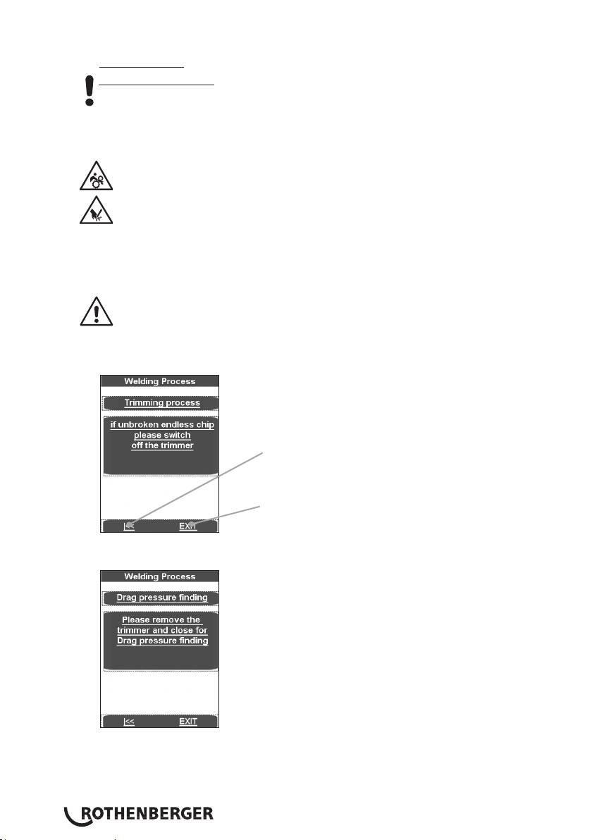
Wait until the cutting disks have stopped. Remove the cutting unit from the basic machine
and put it in the storage case.
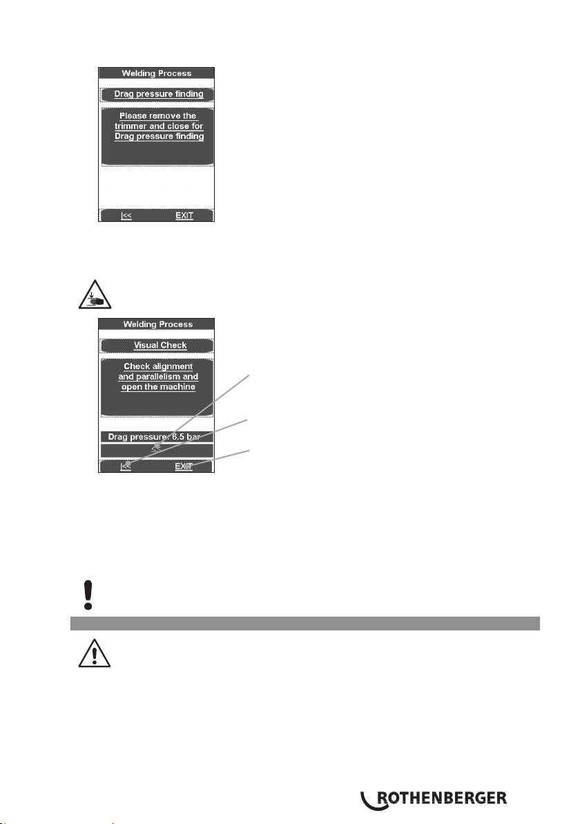
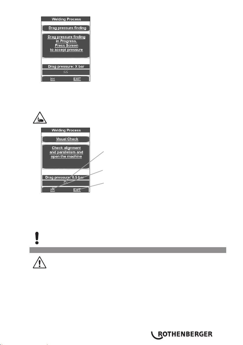
Press text field, the work pieces move together and the drag flow pressure is measured.
The measured drag pressure will automatically be added to the equalization, warm-up and
cutting pressure.
Stay a safe distance away from the machine. Do not stand or reach into the
machine. Keep other people away from the work area.
The arrow keys take the program back to "Drag
pressure finding".
The arrow keys take the program back to "Please insert
the trimmer..."
EXIT takes the program to the main menu without
saving.
Check, whether the pipes are resting firmly in the clamping elements, whether the welding
areas are plane, parallel and axially aligned.
Should the joint surfaces show any misalignment, repeat the trimming procedure. For
best results the workpiece ends should not be mismatched by more than 10% of the wall
thickness and the maximum gap between the joint surfaces no more than 0.5 mm. This
recommendation does not release you from your obligation to observe national welding
guidelines. Clear away any remaining shavings with a clean brush.
CAUTION! Do not touch the trimmed, ready to weld surfaces. Ensure that the
surfaces are free of any and all containments and foreign objects!
3.2.3 Welding
Risk of injury! Keep a safe distance from the machine when mechanically closing
clamps and moving workpieces. Keep hands, limbs and objects such as clothing,
tools etc. away from running machine!
ENGLISH 39
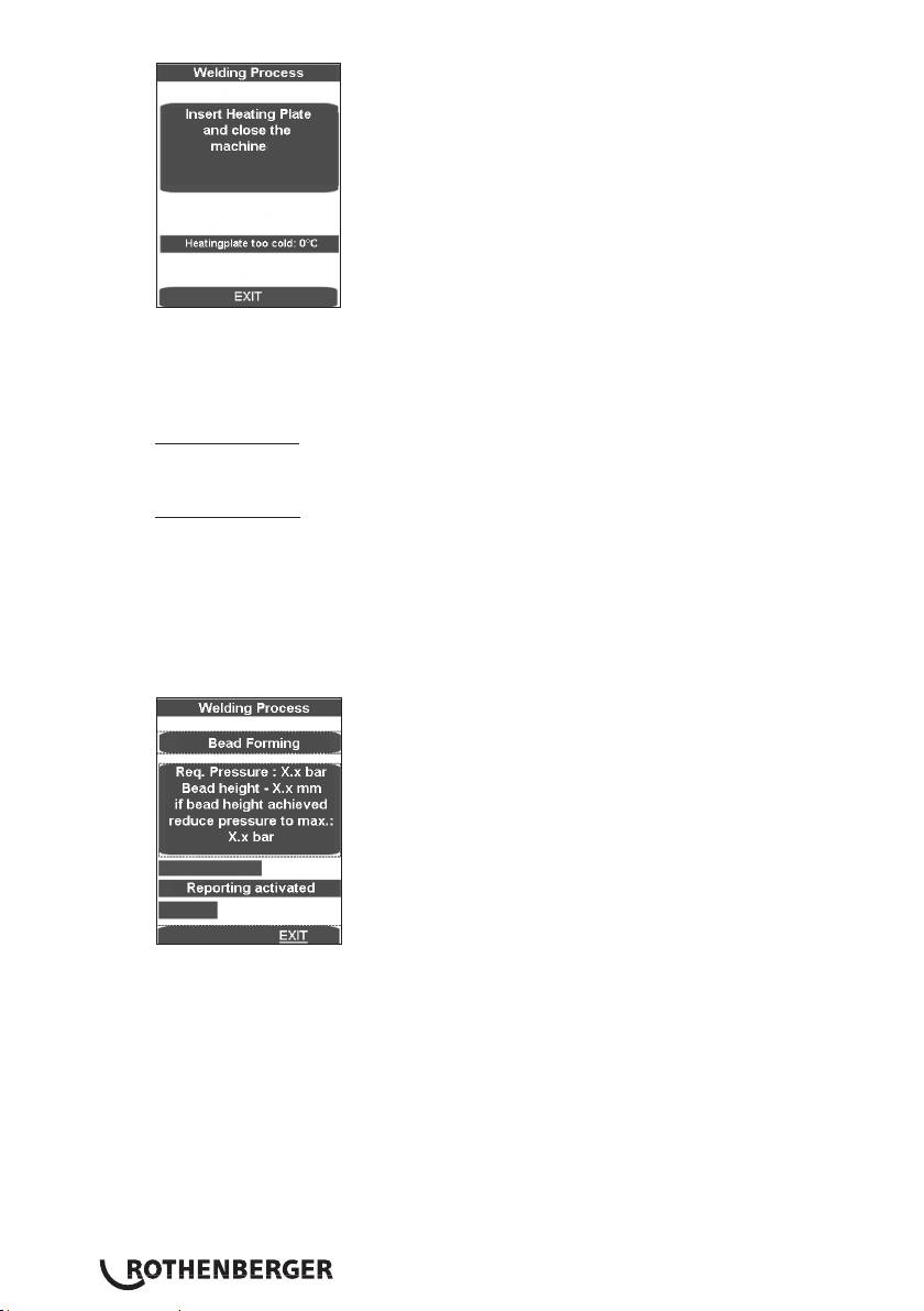
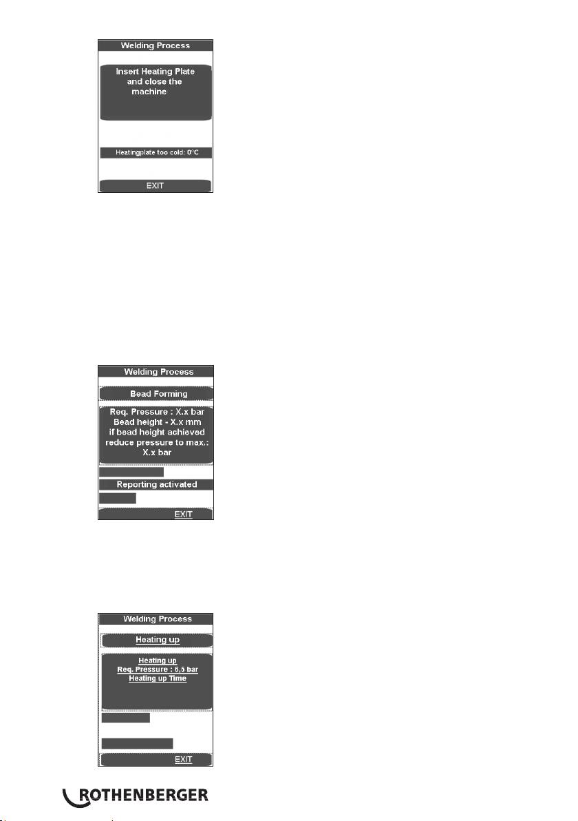
The form shows the temperature of the heating plate.
The display bar shows up in blue if the temperature is too low, and in red when it is too high.
When it is in the target range, it displays as green.
The machine can only be run in the green target range.
Heating plate SA: Insert the heating element between the two work pieces in the basic
machine, and make sure that the heating plate supports are seated in the notches of the
removal device.
Heating plate VA: Place the heating element on both acceptance points in the basic
machine and swivel the hot plates between the pipes.
Move the machine together by pressing the text field. The adjusting pressure is automatically
adjusted and maintained.
Now all welding parameters have been stored, and the log activated.
If the welding process is interrupted using EXIT the message “Termination by the operator“
appears, the pressure is dissipated and the welding parameters are stored. Confirm the
message with OK, then the programme jumps to the main menu.
The upper progress bar shows whether the pressure lies within the correct range (green) or
within a permissible (yellow) tolerance range or whether it lies outside (red) the tolerance
range. The actual pressure is shown on the display (2).
As soon as the necessary bulge height has been uniformly reached on the entire
circumference of both tubes, the pressure is automatically released and the warm-up process
begins.
ENGLISH40
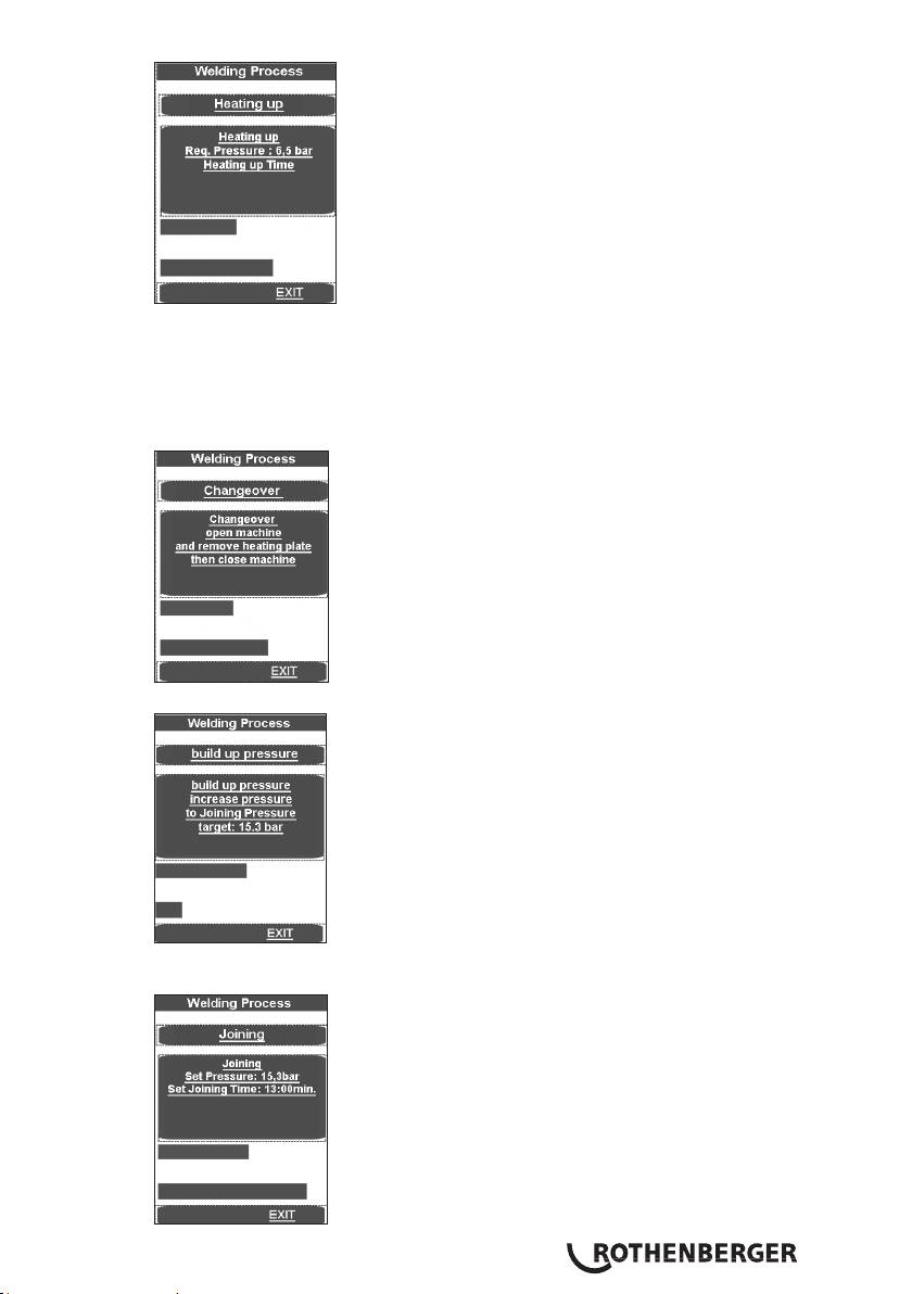
Set the pressure so that the ends of the work pieces can again be lain uniformly and nearly
pressure-free onto the heating element.
A signal sounds shortly before the end of the warm-up time.
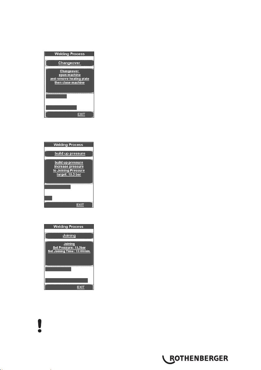
At the end of the warm-up period, the work pieces move apart, the heating element SA must
be removed, or the heating element VA is automatically swung out and the work piece ends
move together.
The pressure is linearly raised to the appropriate joining pressure.
When joining pressure is reached, the program automatically goes to the joining process and
the t4 timer starts.
ENGLISH 41

The upper progress bar shows whether the pressure lies within the correct range (green) or
within a permissible (yellow) tolerance range or whether it lies outside (red) the tolerance
range. The time lapse is shown below. The actual pressure is shown in display (2) and the
remaining joining time in display (9).
The pressure is automatically monitored and regulated. If the hydraulic system repumps too
often (meaning there is high pressure loss), have it checked.
Put the heating element back in the storage case.
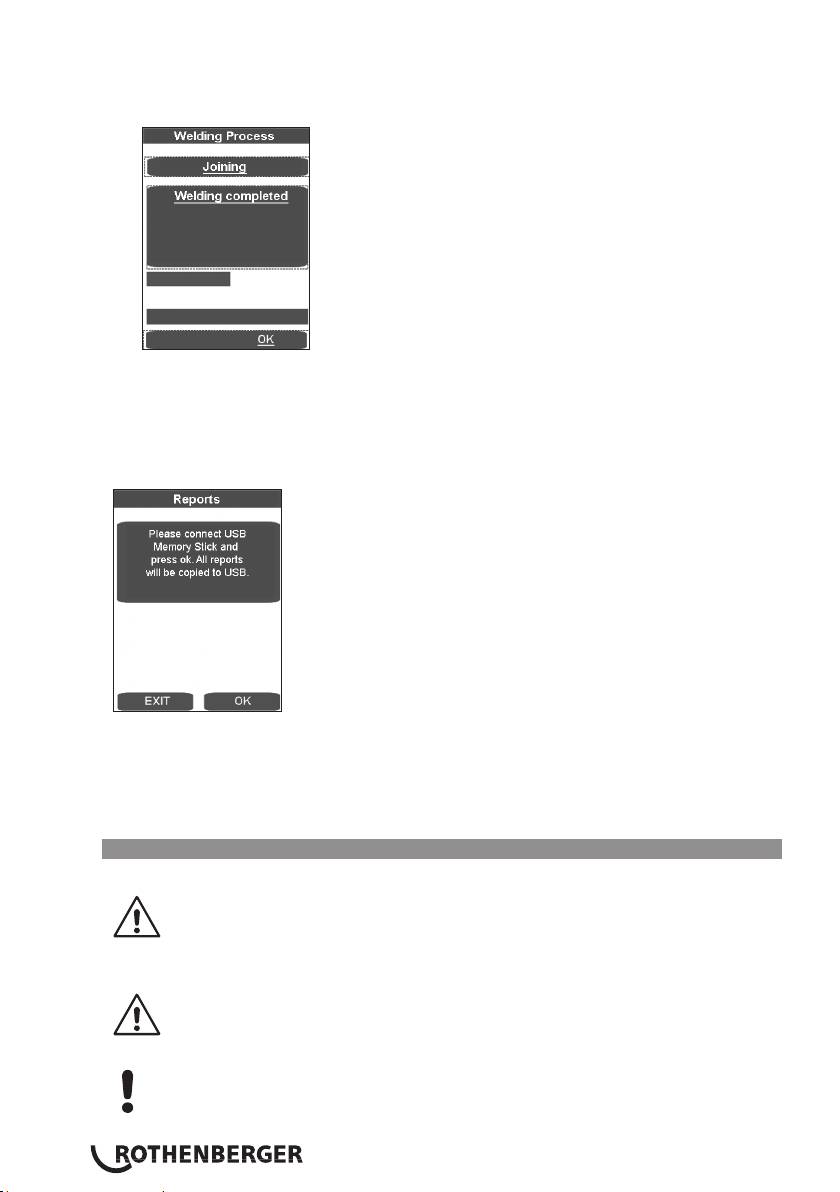
The welding process is ended after the cooling down time has expired, is stored, a signal
sounds and the pressure is dissipated automatically.
Conclude with use of the welding menu by pressing OK.
Dissipate the pressure completely by pressing the button (3).
Unclamp the welded work pieces and remove them.
Move the basic machine apart. The machine is ready for the next welding cycle.
Transferring the log:
In the Log menu item, these can be saved with OK, if a USB stick is connected. The window then
closes automatically.
This report file should be processed using the ROTHENBERGER Dataline 2 software and a
computer.
All welding parameters can be found in the enclosed welding tables.
ENGLISH42
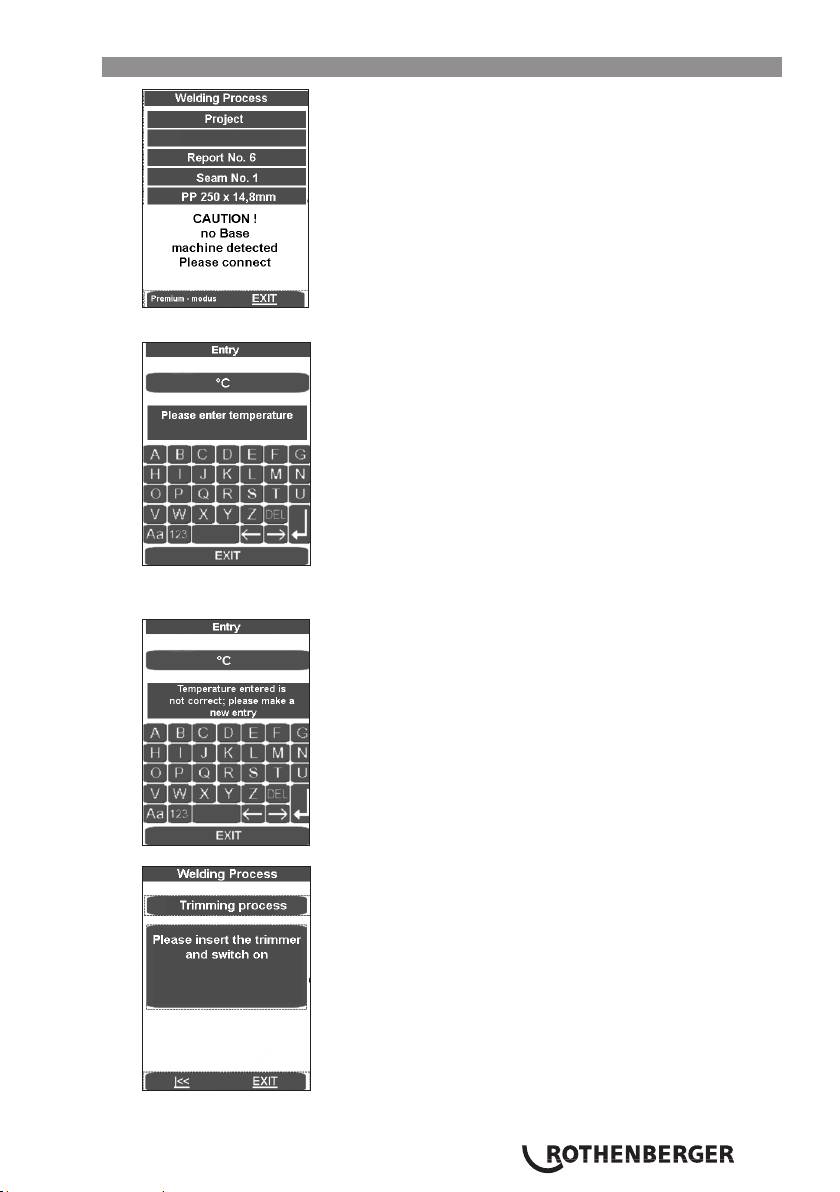
3.2.4 Welding in premium mode
Press Premium mode.
Enter the temperature and press the Enter button. The following appears if the temperature
was not entered correctly:
Pressing the arrow key causes the machine to start up; pressing EXIT causes the programme
to spring into the main menu without saving.
ENGLISH 43
Place the electrical cutting unit between the two work pieces to be welded.
P250-355/8-12B: Switch on the miller motor and lock the switch in place.
P500-630/18-24B Plus: Verify the direction of rotation! The machines were polarised
to turn clockwise before leaving our factory!
Turn on the cutting unit, press buttons (10) and (5) on the hydraulic unit. The cutting disks
must run in the cutting direction. If they don‘t, use an appropriate tool to switch the phase
inverter on the electrical plug.
Risk of serious injury! During operation trimmer unit, stay a safe distance away
from the machine, and do not reach into the rotating knife. Use trimmer in
working position only and return it into the designated carrying frame
immediately after use. Ensure that the safety switch functions properly at all
times to avoid any accidental starting of the trimmer away from the basic
machine.
Close the clamping elements (press buttons 10 + 11). Set the cutting pressure with the
adjusting knob (4). Standard cutting pressure is up to 20 bar, but it can be raised to 40 bar,
see point 3.5.
An excessively high milling pressure can lead to overheating and damage to the
miller drive. When the milling drive is overloaded or at rest, raise the machine
and reduce the pressure (s. 3.5).
After the cutting shavings continuously exit the cutting bit with a shaving thickness of <=
0.2 mm,press the Cutting button (5) and open the clamping elements (Press buttons 10 + 8).
The arrow keys take the program back to „Please
insert the trimmer...“
EXIT takes the program to the main menu without
saving.
Wait until the cutting disks have stopped. Remove the cutting unit from the basic machine
and put it in the storage case.
Use low pressure to bring the work pieces together (press buttons 10 + 11) and set the drag
pressure with the adjusting knob (4).
ENGLISH44
When the machine is running at low speed, press the screen. The measured drag pressure will
automatically be added to the equalization, warm-up and cutting pressure.
Close the clamping elements, set the correct pressure for the pipe, and check to see if the
work pieces are firmly held in the clamping tools.
Stay a safe distance away from the machine. Do not stand or reach into the
machine. Keep other people away from the work area.
The arrow keys take the program back to "Drag
pressure finding".
The arrow keys take the program back to "Please insert
the trimmer..."
EXIT takes the program to the main menu without
saving.
Check to see that the welding surfaces are flat, parallel and axially aligned.
Should the joint surfaces show any misalignment, repeat the trimming procedure. For
best results the workpiece ends should not be mismatched by more than 10% of the wall
thickness and the maximum gap between the joint surfaces no more than 0.5 mm. This
recommendation does not release you from your obligation to observe national welding
guidelines. Clear away any remaining shavings with a clean brush.
CAUTION! Do not touch the trimmed, ready to weld surfaces. Ensure that the
surfaces are free of any and all containments and foreign objects!
3.2.4.1 Welding process in premium mode
Risk of injury! Keep a safe distance from the machine when mechanically closing
clamps and moving workpieces. Keep hands, limbs and objects such as clothing,
tools etc. away from running machine!
ENGLISH 45
The form shows the temperature of the heating plate.
The display bar shows up in blue if the temperature is too low, and in red when it is too high.
When it is in the target range, it displays as green.
Insert the heating element between the two work pieces in the basic machine, and make sure
that the heating plate supports are seated in the notches of the removal device.
Close the machine. The equalization pressure is automatically set. Hold the pressure.
Now all welding parameters have been stored, and the log activated.
If the welding process is interrupted using EXIT the message “Termination by the operator“
appears, the pressure is dissipated and the welding parameters are stored. Confirm the
message with OK, then the programme jumps to the main menu.
The upper progress bar shows whether the pressure lies within the correct range (green) or
within a permissible (yellow) tolerance range or whether it lies outside (red) the tolerance
range. The actual pressure is shown on the display (2).
Release the pressure using the Automatic button (1) as soon as the required bulge height has
been reached evenly around the whole circumference of both pipes. The warming up time t1
begins to run.
ENGLISH46
Set the pressure so that the ends of the work pieces can again be lain uniformly and nearly
pressure-free onto the heating element.
A signal sounds shortly before the end of the warm-up time.
After the warm-up time is over, separate the work pieces, remove the heating element and
bring the work pieces back together.
Stop the bringing together process by releasing the buttons shortly before the ends of
the workpieces make contact (about 1 cm.) and press the buttons again immediately. The
pressure is linearly raised to the appropriate joining pressure.
When joining pressure is reached, the program automatically goes to the joining process and
the t4 timer starts.
The upper progress bar shows whether the pressure lies within the correct range (green) or
within a permissible (yellow) tolerance range or whether it lies outside (red) the tolerance
range. The time lapse is shown below. The actual pressure is shown in display (2) and the
remaining joining time in display (9).
Attention: Hold down the Release button (10) and the Close machine button (11) until the
joining pressure is reached. Then the hydraulic unit shuts off and the buttons can be released.
The pressure is monitored and automatically regulated again. If the hydraulic system repumps
too often (meaning there is high pressure loss), have it checked.
ENGLISH 47
Put the heating element back in the storage case.
The welding process is ended after the cooling down time has expired, is stored, a signal
sounds and the pressure is dissipated automatically.
Conclude with use of the welding menu by pressing OK.
Dissipate the pressure completely by pressing the button (3).
Unclamp the welded work pieces and remove them.
Move the basic machine apart. The machine is ready for the next welding cycle.
Transferring the log:
In the Log menu item, these can be saved with OK, if a USB stick is connected. The window then
closes automatically.
This report file should be processed using the ROTHENBERGER Dataline 2 software and a
computer.
All welding parameters can be found in the enclosed welding tables.
3.2.5 Putting out of operation
Use the button (6) to turn off the hydraulic unit.
Let the heating element cool or stow it in such a way that no adjacent materials
can be ignited!
Remove trimmer unit, heating plate and hydraulic unit mains plugs from power outlet and roll
up cables.
Transport and set the hydraulic unit only in a horizontal position. If it is set at an
angle, oil escapes from the vented plugs with the dipstick!
Disconnect and roll up hydraulic hoses.
Important! Protect couplings from damage and dirt!
ENGLISH48

3.3 General requirements
As weather and ambient conditions can seriously effect welding procedures and joints, it is
essential to duly observe national welding guidelines and ordinances, e. g. DVS Guideline 2207,
Sections 1, 11 and 15.
(Welding requires continuous and due supervision and monitoring!)
3.4 Important information on welding parameters
For welding parameters such as temperature, pressure and time, consult your national welding
guidelines and ordinances, e. g. DVS Guideline 2207, Sections 1, 11 and 15.
Ordering: DVS Media GmbH, Aachener Str. 172, 40223 Düsseldorf
Postfach 10 19 65, 40010 Düsseldorf, Tel.: +49 (0) 211 / 15 91 – 0
Email: media@dvs-hg.de internet: www.dvs-media.info
In the event of doubt, consult the pipe manufacturer for material-specific welding parameters.
The welding parameters specified in the welding tables are strictly reference values.
ROTHENBERGER cannot assume any liability for their accuracy or completeness!
The compensation and joint pressure values specified in the welding tables were calculated using
the following formula:
pressure P [bar] = welding surface A [mm²] x welding factor SF [N/mm²]
surface of cylinder Az [cm²] x 10
Welding factors (SF): PE = 0,15 N/mm², PP = 0,10 N/mm², PVDF = 0,10 N/mm²
(ROWELD P 250/8 B: the total cylinder surface is 6.26 cm²)
(ROWELD P 355/12 B: the total cylinder surface is 6.26 cm²)
(ROWELD P 500/18 B and P 630/24 B: the total cylinder surface is 14.13 cm²)
(ROWELD P 630/24 B Plus the total cylinder surface is 22.38 cm²)
3.5 Setting parameters
To set the parameters with „welder“ rights:
Press the adjusting knob (4) for a long time (about 3 sec.) until P001 blinks in the upper
display (2).
Use the adjusting knob (4) to select the desired parameter P001 to P009. If this value must
be adjusted or displayed, briefly press the adjusting knob (4). The (default) value blinks in the
lower display (9).
Use the adjusting knob (4) to set the value, and press the adjusting knob (4) briefly again.
Then the parameter blinks again in the upper display (2).
To leave the menu, press the release button (10). The values are stored.
How to set parameters with „master“ rights:
Press the adjusting knob (4) for an extended time (about 6 sec.). First the parameter P001
blinks in the upper display (2). Then „CodE“, and the line blinks in the first place in the lower
display (9).
Then use the adjusting knob (4) to enter the code, and briefly press the adjusting knob (4)
(code = 8001 – during first use the code can be changed as desired through parameter P100).
Use the adjusting knob (4) to select the desired parameter, P101 to P114. If this value must
be adjusted or displayed, briefly press the adjusting knob (4). The (default) value blinks in the
lower display (9).
Use the adjusting knob (4) to set the value, and press the adjusting knob (4) briefly again.
Then the parameter blinks again in the upper display (2).
To leave the menu, press the release button (10). The values are stored.
Parameter
Description default Unit min max Rights
name
P001 Remaining energy saver time 99 min 0 99 Welder
P002* Power saving function active 0 0 3 Welder
ENGLISH 49
P003 Heating plate temperature offset 5 °C -25 25 Welder
P004 Pmax for cutting 20 bar 10 50 Welder
P005 Target pressure 1/10 bar Welder
P006 Target temperature 210 °C P103 P104 Welder
P007 Timer T1 target value 45 sec 1 1500 Welder
P008 Timer T4 target value 6 min 1 99 Welder
P009 Pstart for cutting 10 bar 0 P004 Welder
P101 Deviation for repumping 5 % 1 50 Master
P102 Lifting time after cutting 10 1/10 sec 0 100 Master
P103 Set temperature (min) 160 °C 0 300 Master
P104 Set temperature (max) 270 °C 0 300 Master
P105 Button lock (yes/no) 5 sed 0 50 Master
P106 Lifting pressure 135 bar 10 160 Master
P107 Full runtime until buzzer goes on 50 1/10 sec 0 200 Master
P100 Change code 8001 Master
* P002 - Power saving function:
0 - none,
1 - when the miller is running the heating element will be switched off,
2 - when the hydraulic motor is running the heating element will be switched off,
3 - when t4 is running the heating element will be switched off.
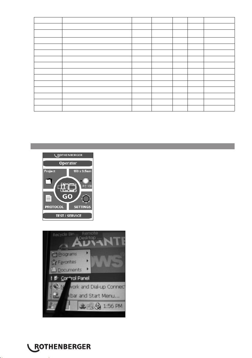
3.6 Set date and time
Close the program by clicking briefly in the upper left corner.
Press Start, Setting and then Control Panel.
The taskbar is hidden and can be called back up by pressing on the lower left corner.
ENGLISH50
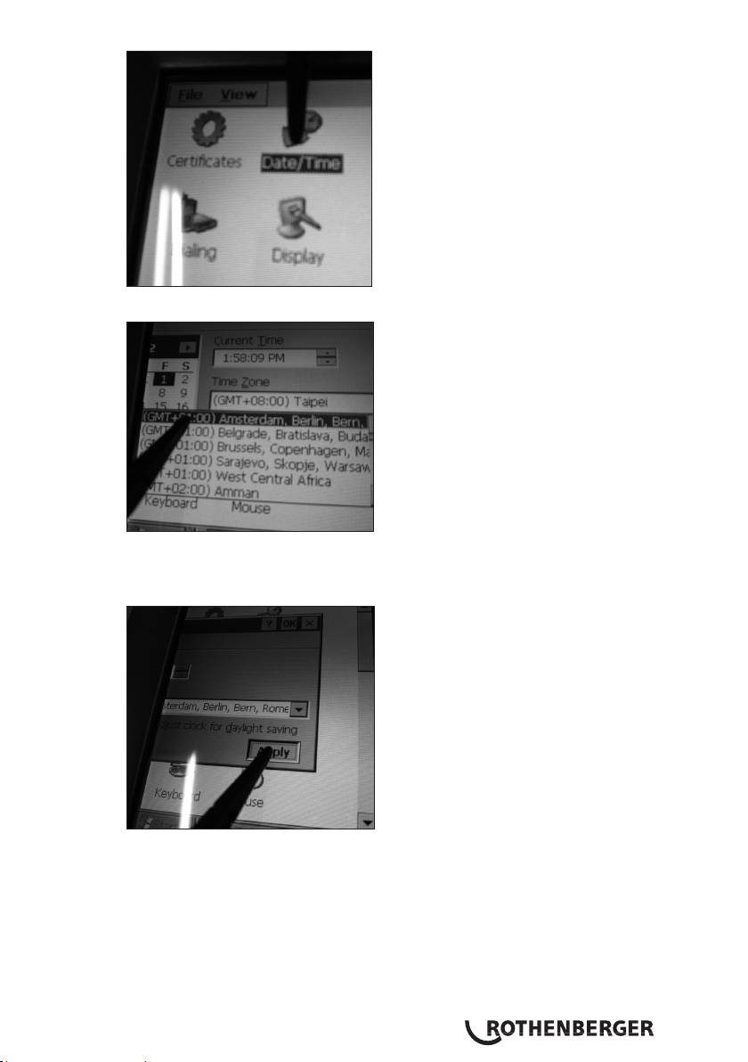
Click Date/Time.
Set up the entry form by touching and dragging the date/time bar. Select the appropriate
time zone or enter the current time.
Attention! Pay attention to AM/PM! 1:58:09 PM = 13:58:09 / 1:58:09 AM = 01:58:09
Confirm with „Apply“ and „OK“. Close the control panel with X.
ENGLISH 51
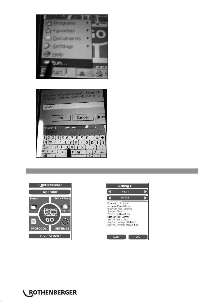
Press the „Start“ and „Run“ buttons.
On the keyboard that appears, enter reboot and press „OK“. The PC restarts.
3.7 Setting up or selecting machine configurations
To select or set up machine configurations, press the SETTINGS button.
The desired machine configuration can be selected using the arrow keys.
To set up a new configuration, use the right arrow key to start the next number, such as 2.
ENGLISH52
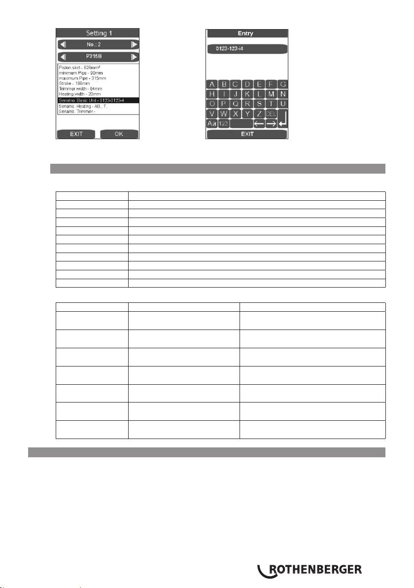
Pressing on the corresponding display field brings up the entry form. The data can be deleted
with DEL and reentered. These data are later placed into the log.
3.8 Error messages
Touch PC and log:
Error message Description
Code 1 Equalization pressure too high
Code 2 Equalization pressure too low
Code 4 Warm-up pressure too high
Code 64 Changeover time too long
Code 128 Pressure dissipation time too long
Code 256 Joining pressure too high
Code 512 Joining pressure too low
Code 2048 Heating element too cold
Code 4096 Interruption by operator
Code 131072 Heating element too hot
Controls:
Error message Description Troubleshooting
SER Service date reached, service
Have service performed
due
ERR1 Absolute pressure not
Check oil level, check pressure sensor,
reached
defective valve, defective motor
PE-2 Pressure sensor -24V
Replace pressure sensor
defective
ERR5 Oil temperature 70°C – Stop! Wait until the oil temperature is below
50°C
HE-1 Heating element not
Replace the sensor
connected, sensor break
HE-0 Heating element too hot Remeasure temperature, check
settings, replace sensor
HE-2 Heating element too cold Remeasure temperature, check
settings, replace sensor
4 Care and maintenance
To ensure that the welding machine functions properly, observe the following maintenance
recommendations:
• The guide rods must be kept free of dirt and grime. Replace guide rods whenever surface
shows signs of erosion or damage, otherwise hydraulic system may loose pressure.
• To achieve perfect welding results, it is essential to keep the heating plate clean. If the surface
is damaged or shows signs of erosion, the surface must be recoated or replaced. Material
residues on the heating plate surface reduces the non-sticking properties of the coating.
Remove all residues with non-linting paper and alcohol (heating plate must be cool!).
ENGLISH 53
• Change hydraulic oil (HLP – 46, no.: 53649) every twelve months.
• To avoid malfunctions, regularly check the hydraulic unit for leaks, proper fit of connections
as well as the power cable for signs of damage or wear.
• Protect the fast-on couplings on both the hydraulic unit as well as the hydraulic hoses from
dirt and grime. Remove any dirt or foreign objects prior to connecting.
• The trimmer unit is equipped with two bi-directional blades. Rotate or replace blades
whenever trimming performance is no longer up to expectations.
• Always ensure that the pipe and workpiece ends, in particular the butt surfaces are clean.
Dirt or other foreign substances will shorten the serviceable life of the blades considerably
Pursuant to welding guidelines the welding machine must be inspected annually
by the manufacturer or an authorised service workshop. Machines subjected to
above average use or strain should be inspected at shorter intervals.
4.1 Machine and tool care
(Follow the maintenance instructions in item 4!)
Sharp and clean tools produce better work results and are safer.
Replace blunt, broken or lost parts immediately. Check whether the accessories are securely
connected to the machine.
Use only original spare parts from the manufacturer for maintenance work. Repairs must be
carried out only by professionally qualified personnel.
Disconnect the machine from the mains when it is not in use, prior to care and maintenance
work and before changing accessory parts.
Prior to reconnection to the mains, it must be ensured that the machine and the accessory tools
are switched off.
When extension cables are used, they must be checked for their safety and operativeness. Only
cables approved for outdoor use must be used.
Tools and machines whose housing or handles, especially those made of plastic, are cracked or
warped must not be used.
Dirt and moisture in such cracks conduct electric current. This can lead to an electric shock if the
insulation is damaged in the tools or in the machine.
Note: Furthermore, we refer to the accident prevention regulations.
5 Accessories
The relevant accessories and an order form can be found from Page 451 onwards.
6 Disposal
Components of the unit are recyclable material and should be put to recycling. For this purpose
registered and certified recycling companies are available. For an environmentalfriendly disposal of
the non-recyclable parts (e.g. electronic waste) please contact your local waste disposal authority.
For EU countries only:
Do not dispose of electric tools with domestic waste. In accordance with European
Directive 2012/19/EU on waste electrical and electronic equipment and its implementation
as national law, electric tools that are no longer serviceable must be collected separately
and utilised for environmentally compatible recycling.
ENGLISH54

Table des matières Page
1 Consignes de sécurité 56
1.1 Utilisation conforme aux dispositions 56
1.2 Consignes générales de sécurité 56
2 Données techniques, voir le fascicule „données techniques“
3 Fonctionnement de l’appareil 58
3.1 Description de l’appareil 58
3.1.1 Machine de base (fig. A) 58
3.1.2 Unité hydraulique (fig. B) 58
3.2 Mode d’emploi 59
3.2.1 Mise en service 59
3.2.2 Mesures de préparation du soudage 62
3.2.3 Soudage 66
3.2.4 Soudure en mode Premium 69
3.2.4.1 Processus de soudure Premium 71
3.2.5 Mise hors service 74
3.3 Exigences générales 75
3.4 Remarques importantes concernant les paramètres de soudage 75
3.5 Régler les paramètres 75
3.6 Régler l‘heure et la date 76
3.7 Créer ou sélectionner la configuration de la machine 78
3.8 Messages d’erreur 79
4 Entretien et maintenance 80
4.1 Entretien de la machine et des outils 80
5 Accessoires 81
6 Elimination des déchets 81
Pictogrammes contenus dans ce document:
Danger!
Ce pictogramme signale un risque de blessure pour les personnes.
Attention!
Ce pictogramme signale un risque de dommage matériel ou de préjudice
pour l’environnement.
Nécessité d’exécuter une action
FRANÇAIS 55

1 Consignes de sécurité
1.1 Utilisation conforme aux dispositions
Les ROWELD P250-630/8-24B Plus Premium CNC sont spécialement conçues pour effectuer les
soudures des tuyaux en PE, PP et PVDF selon les données techniques.
1.2 Consignes générales de sécurité
ATTENTION ! Veuillez observer les mesures de sécurité suivantes afin d’éviter les
électrocutions et les dangers de blessures ou d’incendies pendant l’utilisation des outils
électriques.
Veuillez lire ces consignes avant d’utiliser cet outil électrique et conservez-les
soigneusement.
Entretien et maintenance :
1 Nettoyage, entretien et graissage réguliers. Débranchez avant tous les réglages, les
travaux de maintenance ou les réparations.
2 Confiez la réparation de votre appareil uniquement à des personnes qualifiées
utilisant des pièces de rechange d’origine Ceci permet de garantir la sécurité de l’appareil
à long terme.
Travaux sécurisés :
1 Maintenez l’espace de travail en ordre. Le désordre dans l’espace de travail peut
provoquer des accidents.
2 Tenez compte des influences de l’environnement. N’exposez pas votre outil électrique
à la pluie. N’utilisez pas votre outil électrique dans un environnement humide ou mouillé.
Assurez un bon éclairage à votre espace de travail. N’utilisez pas votre outil électrique à des
endroits soumis à des risques d’incendie ou d’explosion.
3 Protégez-vous d’une électrocution. Évitez les contacts corporels avec des parties mises à
terre (par. ex. tubes, radiateurs, cuisinières électriques, appareils de refroidissement).
4 Ne laissez pas d’autres personnes s’approcher. Interdisez à d’autres personnes, aux
enfants en particulier, de toucher l’outil électrique ou le câble. Maintenez-les à distance de
l’espace de travail.
5 Rangez l’outil électrique inutilisé dans un endroit protégé. Les outils électriques
inutilisés doivent être déposés dans un endroit sec, surélevé et fermé, hors de portée des
enfants.
6 Ne surchargez pas votre outil électrique. Le travail est plus sûr et plus facile dans la zone
de puissance.
7 Utilisez l’outil électrique adéquat. N’utilisez pas une machine à faible puissance pour des
travaux lourds. N’utilisez pas l’outil électrique à des fins non prévues pour lui. Par exemple,
n’utilisez pas de scie circulaire manuelle pour couper des troncs d’arbres ou des bûches.
8 Portez des vêtements adéquats. Ne portez pas de vêtements larges ou de bijoux,
ils pourraient être saisis par les pièces mobiles. Des chaussures antidérapantes sont
recommandées pour les travaux effectués en plein air. Mettez vos cheveux dans un filet.
9 Utilisez l’équipement de protection. Portez des lunettes de sécurité. Portez un masque
respiratoire pendant les travaux provoquant de la poussière.
10 Raccordez le dispositif d’aspiration. Au cas où des raccords pour les dispositifs d’aspiration
et de collection sont disponibles, vérifiez qu’ils sont bien branchés et correctement utilisés.
11 N’utilisez pas l’outil électrique à des fins non prévues pour lui. Ne tirez pas sur le
FRANÇAIS56

câble pour débrancher l’appareil. Protégez le câble de la chaleur, de l’huile et des arêtes
tranchantes.
12 Assurez la pièce usinée. Utilisez le dispositif de tension ou un étau à vis afin de maintenir la
pièce usinée. Elle est maintenue plus sûrement qu’à la main.
13 Évitez les positions corporelles anormales. Veillez à vous assurer une position sûre et
gardez toujours l’équilibre.
14 Soignez minutieusement vos outils. Maintenez les outils de coupes propres et tranchants
afin de vous faciliter le travail. Suivez les consignes pour le graissage et le changement d’outil.
Contrôlez régulièrement les conduites de raccordement des outils électriques et faites les
réparer par un professionnel agréé en cas de détérioration. Contrôlez régulièrement les
rallonges et remplacez-les en cas de détériorations. Maintenez la poignée sèche, propre et
exempte de graisse ou d’huile.
15 Retirez la fiche de la prise de courant. Lorsque vous n’utilisez pas l’outil électrique, avant
l’entretien ou lors du changement d’outils comme la scie, la perceuse, la fraise.
16 Ne laissez pas la clé d’outil à l’intérieur. Vérifiez que la clé et l’outil de réglage soient
retirés avant la mise en marche.
17 Évitez les mises en marche involontaire. Assurez-vous que l’interrupteur est éteint lorsque
vous insérez la fiche dans la prise.
18 Utilisez la rallonge lors de travaux à l’extérieur. Utilisez uniquement des rallonges
homologuées et marquées en conséquence pour les travaux à l’air libre.
19 Soyez attentif. Soyez concentré sur votre travail. Faites preuve de bon sens lorsque vous
travaillez. N’utilisez aucun outil électrique si vous n’êtes pas concentré.
20 Vérifiez le bon état de l’outil électrique. Avant de continuer à utiliser l’outil électrique,
vérifiez soigneusement les dispositifs de sécurité ou les pièces légèrement endommagées
et assurez-vous que le fonctionnement est impeccable et adéquat. Vérifiez que les parties
mobiles fonctionnent de manière impeccable et ne coincent pas ainsi que le parfait état des
pièces. Toutes les pièces doivent être montées correctement et remplir toutes les conditions
afin de garantir un fonctionnement impeccable de l’outil électrique.
Les pièces et les dispositifs de sécurité endommagés doivent être réparés ou changés par
un atelier agréé, à moins que le mode d’emploi donne d’autres consignes. Les interrupteurs
endommagés doivent être remplacés dans un atelier pour notre clientèle.
N’utilisez pas un outil électrique qui ne peut être mis en marche ou arrêté.
21 Attention. L’utilisation d’autres outils et accessoires peut provoquer des blessures.
22 Faites réparer les outils électriques par un électricien qualifié. Cet outil électrique
correspond aux dispositions de sécurités applicables. Les réparations doivent uniquement être
effectuées par un électricien qualifié et avec les pièces de rechange originales ; dans le cas
contraire, cela pourrait provoquer des accidents.
2 Données techniques, voir le fascicule „données techniques“
FRANÇAIS 57

3 Fonctionnement de l’appareil
3.1 Description de l’appareil
Les ROWELD P250-630/8-24B Plus Premium CNC sont des machines de soudage de bout à
bout à éléments chauffants avec module CNC pour la commande exacte, le respect et le stockage
des paramètres de soudure selon la directive DVS (Association allemande de soudage), le
transfert de protocole via un raccord USB. Elles sont spécifiquement conçues pour une utilisation
en relation avec les chantiers et tout particulièrement dans les tranchées de canalisation. Les
machines peuvent bien sur egalement etre utilisees dans des ateliers.
Les fonctions multiples des soudeuses de « type ROWELD » permettent de fabriquer de manière
sûre les joints soudés de tubes en PE, PP et en PVDF suivants avec des diamètres extérieurs de 90
à 630 mm/5 à 24“ dans tous les domaines d’utilisation :
I. tube - tube
II. tube - coude de tube
III. tube - pièce en T
IV. tube - collerette à souder
Les machines sont essentiellement composées des éléments suivants :
machine de base, jeux d’inserts de serrage de réduction, unité hydraulique avec module de CNC,
équipement de fraisage, élément thermique, caisson de rangement.
Pour souder des collerettes à souder, la rondelle de serrage à quatre mâchoires livrable comme
accessoire doit être utilisée.
ROWELD P250/8B: Lors du soudage de tubes coudés à rayon réduit ayant le diamètre maximal
de la machine, il convient d’utiliser l’outil de serrage en biseau (partie supérieure) disponible en
tant qu’accessoire.
ROWELD P500-630/18-24B Plus: pour mettre en place et soulever la fraise et l’élément
thermique, le dispositif de soulèvement électrique livrable comme accessoire peut être utilisé.
3.1.1 Machine de base (fig. A)
1 Eléments de serrage mobiles 3 pièce d’écartement avec entailles d’arrêt
2 Elément de serrage déplaçable 4 Dispositif d’évacuation de l’élément thermique
3.1.2 Unité hydraulique (fig. B)
1 Touche automatique 12 Touche minuterie (durée)
2 Affichage pression 13 Prise dispositif de fraisage
3 Touche relâcher la pression 14 Manchon raccord rapide
4 Bouton rotatif 15 Prise raccord rapide
5 Touche fraisage 16 Prise de courant corps de chauffe
6 Touche marche-arrêt 17 Fiche secteur
7 Touche chauffage 18 Arrêt d'urgence
8 Machine « Mise en marche » 19 PC tactile
9 Affichage température et heure 20 Raccord de remplissage d’huile avec jauge
10 Touche de validation 21 Port USB
11 Machine « Mise à l’arrêt » 22 Prise de courant de la machine de base
L’unité hydraulique permet d’activer les fonctions de la soudeuse désignées par les symboles
suivants :
Touche groupe hydraulique Mise en marche et mise à l’arrêt
Mettre en marche le corps de chauffe en appuyant sur la touche « Chauf-
fage ». Régler la température désirée de l’élément de chauffe en ap-
puyant sur la touche « Chauffage » et tourner le bouton rotatif, la valeur
désirée s’affiche sous température puis est remplacée par la valeur effecti-
ve.
FRANÇAIS58
