Rothenberger ROWELD P250-630 B Plus Premium CNC – страница 2
Инструкция к Rothenberger ROWELD P250-630 B Plus Premium CNC
3.2.4.1 Schweißvorgang Premium-Modus
Quetschgefahr! Beim Zusammenfahren der Spannwerkzeuge und Rohre
grundsätzlich sicheren Abstand zur Maschine halten. Niemals in die Maschine
stellen!
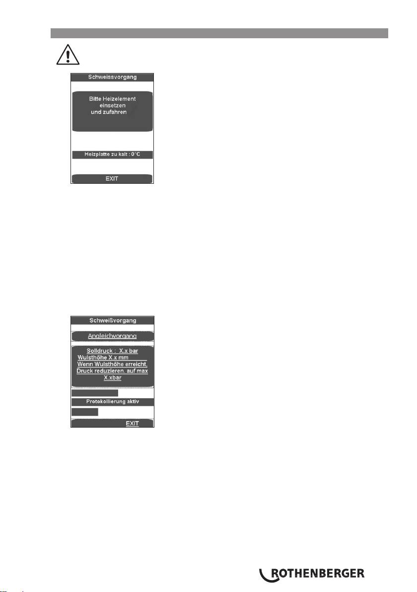
In der Maske wird die Temperatur der Heizplatte angezeigt.
Der Anzeigebalken erscheint wenn die Temperatur zu niedrig ist in blau, wenn sie zu hoch ist
in rot und wenn sie im Sollbereich ist in grün.
Das Heizelement zwischen die beiden Werkstücke in die Grundmaschine einsetzen und
darauf achten, dass die Auflagen der Heizplatte in den Kerben der Abzugsvorrichtung sitzen.
Maschine zusammenfahren, der Angleichdruck wird automatisch eingestellt und Druck
halten.
Jetzt werden alle Schweißparameter gespeichert, Protokollierung aktiviert.
Wird der Schweißprozess mit EXIT abgebrochen, erscheint die Meldung „Abbruch durch
Bediener“, der Druck wird abgelassen und die Schweißparameter gespeichert. Die Meldung
mit OK bestätigen, das Programm springt ins Hauptmenü.
Der obere Laufbalken zeigt an ob der Druck im richtigen Bereich (grün) oder im zulässigen
(gelb) Toleranzbereich oder außerhalb (rot) des Toleranzbereichs liegt. Der tatsächliche Druck
wird in der Anzeige (2) angezeigt.
Sobald die erforderliche Wulsthöhe gleichmäßig am gesamten Umfang beider Rohre erreicht
ist, Druck mit Taste Automatik (1) ablassen. Die Anwärmzeit t1 beginnt zu laufen.
DEUTSCH 19
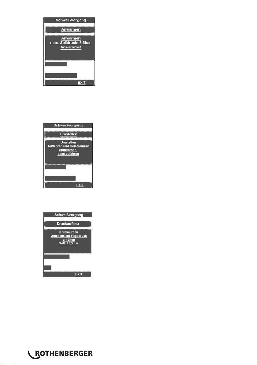
Der Druck wird so eingestellt, dass noch ein gleichmäßiges, nahezu druckloses Anliegen der
Werkstückenden am Heizelement gewährleistet ist.
Kurz vor Ende der Anwärmzeit ertönt ein Signal.
Nach Ablauf der Anwärmzeit Werkstücke auseinanderfahren, das Heizelement entnehmen
und die Werkstückenden zusammenfahren.
Kurz vor dem Kontakt der Werkstückenden (ca.1cm) das Zusammenfahren durch Loslassen
der Tasten stoppen und sofort wieder drücken. Der Druck wird linear auf den entsprechenden
Fügedruck erhöht.
Bei Erreichen des Fügedruckes springt das Programm automatisch in den Fügevorgang und
der Timer t4 startet.
DEUTSCH20

Der obere Laufbalken zeigt an ob der Druck im richtigen Bereich (grün) oder im zulässigen
(gelb) Toleranzbereich oder außerhalb (rot) des Toleranzbereichs liegt. Der untere zeigt den
Zeitablauf an. Der tatsächliche Druck wird in der Anzeige (2) und die restliche Fügezeit t4 in
der Anzeige (9) angezeigt.
Achtung: Tasten Freigabe (10) und Maschine Zu (11) solange gedrückt halten bis der
Fügedruck erreicht ist, danach schaltet sich die Hydraulik aus und die Tasten können
losgelassen werden.
Der Druck wird überwacht und automatisch nachreguliert. Bei übermäßig häufigem
Nachpumpen (hoher Druckverlust) das Hydrauliksystem überprüfen lassen.
Heizelement in den Einstellkasten zurücksetzen
Nachdem die Abkühlzeit abgelaufen ist wird der Schweißprozess beendet, gespeichert, es
ertönt ein Signal und der Druck wird automatisch abgelassen.
Das Schweißmenü mit OK beenden.
Druck mit Taste (3) vollständig ablassen.
Die verschweißten Werkstücke ausspannen und entnehmen.
Grundmaschine auseinanderfahren. Die Maschine ist bereit für den nächsten Schweißzyklus.
Übertragung der Protokolle:
DEUTSCH 21

Im Menüpunkt Protokolle lassen sich diese, sowie ein USB-Stick angeschlossen ist, mit OK
abspeichern. Das Fenster schließt danach automatisch.
Diese Protokolldatei ist mit der ROTHENBERGER Dataline 2-Software und einem Computer zu
bearbeiten.
Die gesamten Schweißparameter können den beiliegenden Schweißtabellen entnommen werden.
3.2.5 Außerbetriebnahme
Hydraulikaggregat mit Taste (6) ausschalten.
Heizelement abkühlen lassen bzw. so verstauen, das keine angrenzenden Stoffe
entzündet werden können!
Stecker von Fräseinrichtung, Heizelement und Hydraulikaggregat aus den Steckdosen ziehen
und Kabel aufwickeln.
Hydraulikaggregat nur waagerechter Position transportieren und abstellen, bei
Schrägstellung tritt Öl aus dem Be- und Entlüftungsstopfen mit Peilstab!
Hydraulikschläuche abkuppeln und aufwickeln.
Achtung! Kupplungen vor Schmutz schützen!
3.3 Allgemeine Anforderungen
Da Witterung - und Umgebungseinflüsse die Schweißung entscheidend beeinflussen, sind
unbedingt die entsprechenden Vorgaben in den DVS - Richtlinien 2207 Teil 1, 11 und 15
einzuhalten. Außerhalb Deutschlands gelten die entsprechenden nationalen Richtlinien.
(Die Schweißarbeiten sind ständig und sorgfältig zu überwachen!)
3.4 Wichtige Hinweise zu den Schweißparametern
Alle erforderlichen Schweißparameter wie Temperatur, Druck und Zeit sind den DVS - Richtlinien
2207 Teil 1, 11 und 15 zu entnehmen. Außerhalb Deutschlands gelten die entsprechenden
nationalen Richtlinien.
Bezug: DVS Media GmbH, Aachener Str. 172, 40223 Düsseldorf
Postfach 10 19 65, 40010 Düsseldorf, Tel.: +49 (0) 211 / 15 91 – 0
Email: media@dvs-hg.de internet: www.dvs-media.info
Im Einzelfall sind unbedingt die materialspezifischen Bearbeitungsparameter der Rohrhersteller
einzuholen.
Die in beigefügten Schweißtabellen genannten Schweißparameter sind Anhaltswerte, für die die
Firma ROTHENBERGER keine Gewähr übernimmt!
Die in den Schweißtabellen angegebenen Werte für den Angleich - und Fügedruck wurden nach
folgender Formel berechnet:
Schweißfläche A [mm²] x Schweißfaktor SF [N/mm²]
Schweißdruck P [bar] =
Zylinderfläche Az [cm²] x 10
Schweißfaktor (SF): PE = 0,15 N/mm², PP = 0,10 N/mm², PVDF= 0,10 N/mm²
(Die Gesamtzylinderfläche der ROWELD P 250/8 B beträgt 6, 26 cm²)
(Die Gesamtzylinderfläche der ROWELD P 355/12 B beträgt 6, 26 cm²)
(Die Gesamtzylinderfläche der ROWELD P 500/18 B und P 630/24 B beträgt 14, 13 cm²)
(Die Gesamtzylinderfläche der ROWELD P 630/24 B Plus beträgt 22, 38 cm²)
DEUTSCH22

3.5 Parameter einstellen
Parameter mit Berechtigung „Schweißer“ einstellen:
Drehknopf (4) lang (ca. 3 Sek.) drücken, bis P001 in oberer Anzeige (2) blinkt.
Mit Drehknopf (4) gewünschten Parameter P001 bis P009 auswählen. Wenn dieser Wert
verstellt bzw. angezeigt werden soll, kurz den Drehknopf (4) drücken, der Wert (default)
blinkt in unterer Anzeige (9).
Wert mit Drehknopf (4) einstellen und Drehknopf (4) wiederum kurz drücken, danach blinkt
wieder der Parameter in der oberen Anzeige (2).
Zum Beenden des Menüs Freigabetaste (10) drücken, Werte werden gespeichert.
Parameter mit Berechtigung „Meister“ einstellen:
Drehknopf (4) länger (ca. 6 Sek.) drücken, erst blinkt der Parameter P001 in oberer Anzeige
(2), dann „CodE“ und in der unteren Anzeige (9) blinkt der Strich in der ersten Stelle.
Mit Drehknopf (4) den Code eingeben und kurz den Drehknopf (4) drücken (Code = 8001 –
bei Erstinbetriebnahme, über Parameter P100 kann der Code beliebig geändert werden).
Mit Drehknopf (4) gewünschten Parameter P101 bis P114 auswählen. Wenn dieser Wert
verstellt bzw. angezeigt werden soll kurz den Drehknopf (4) drücken, der Wert (default) blinkt
in unterer Anzeige (9).
Wert mit Drehknopf (4) einstellen und Drehknopf (4) wiederum kurz drücken, danach blinkt
wieder der Parameter in der oberen Anzeige (2).
Zum Beenden des Menüs Freigabetaste (10) drücken, Werte werden gespeichert.
Parameter-
Bezeichnung default Einheit min max Berechtigung
name
P001 Energiesparfunktion Restzeit 99 min 0 99 Schweißer
P002* Leistungssparfunktion aktiv 0 0 3 Schweißer
P003 Offset Heizplattentemperatur 5 °C -25 25 Schweißer
P004 Pmax zum Fräsen 20 bar 10 50 Schweißer
P005 Solldruck 1/10bar Schweißer
P006 Solltemperatur 210 °C P103 P104 Schweißer
P007 Timer T1 Sollwert 45 sek 1 1500 Schweißer
P008 Timer T4 Sollwert 6 min 1 99 Schweißer
P009 Pstart zum Fräsen 10 bar 0 P004 Schweißer
P101 Abweichung zum Nachpumpen 5 % 1 50 Meister
P102 Auffahrzeit nach Fräsen 10 1/10sek 0 100 Meister
P103 Einstelltemperatur (min) 160 °C 0 300 Meister
P104 Einstelltemperatur (max) 270 °C 0 300 Meister
P105 Taste-Verriegelung (Ja/Nein) 5 sek 0 50 Meister
P106 Druck zum Auffahren 135 10 160 Meister
P107 Vorlaufzeit zum Schalten des
50 1/10sek 0 200 Meister
Summers
P100 Code ändern 8001 Meister
* P002 - Leistungssparfunktion:
0 - keine,
1 - wenn Fräser läuft wird Heizelement ausgeschaltet,
2 - wenn Hydraulikmotor läuft wird Heizelement ausgeschaltet,
3 - wenn t4 läuft wird Heizelement ausgeschaltet.
DEUTSCH 23
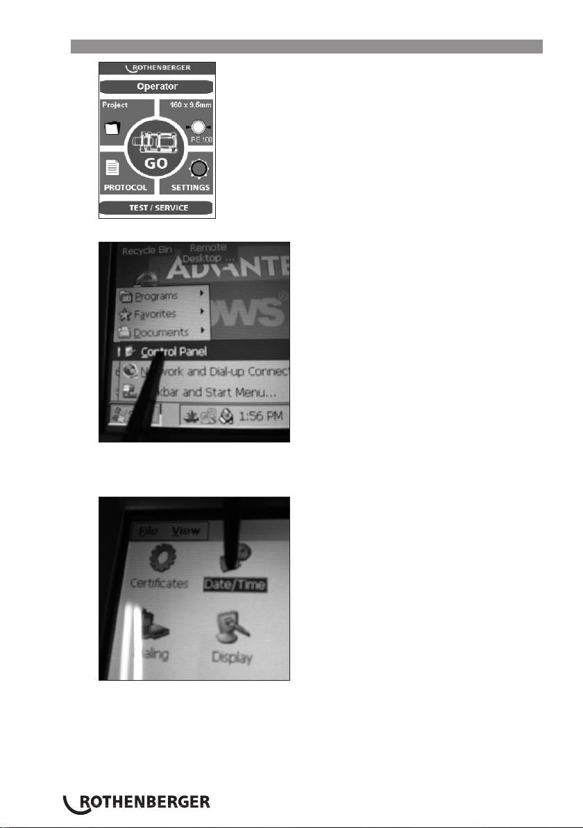
3.6 Datum und Uhrzeit einstellen
Programm durch Klicken in die obere linke Ecke schliessen.
Start, Setting und anschließend Control Panel drücken.
Die Startleiste ist ausgeblendet und kann durch Drücken auf die untere linke Ecke aufgerufen
werden.
Date/Time klicken
DEUTSCH24
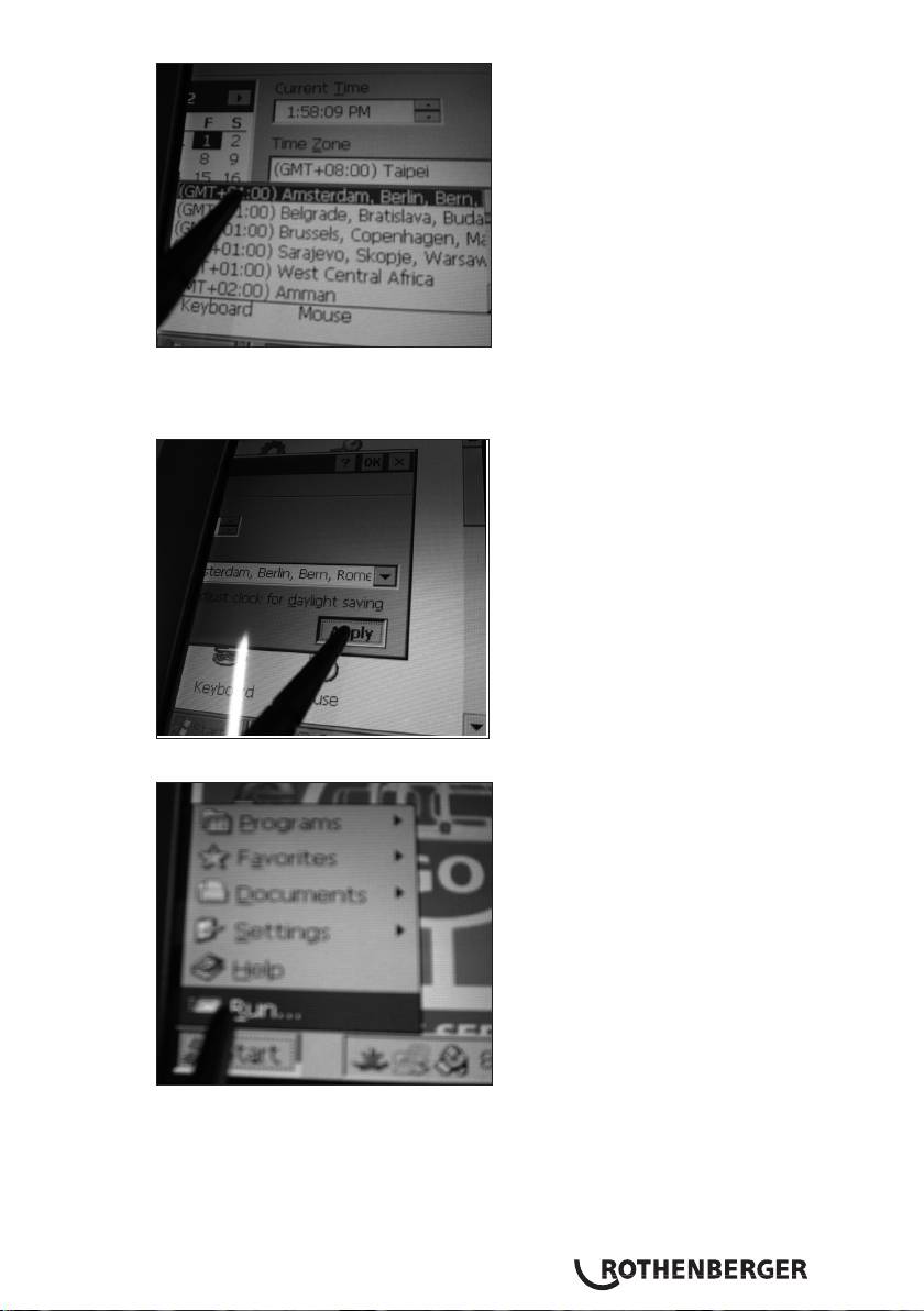
Eingabemaske durch Berühren und Verschieben der Date/Time-Leiste einrichten.
Entsprechende Zeitzone auswählen oder die Uhrzeit Current Time eingeben.
Achtung! AM / PM beachten! 1:58:09 PM = 13:58:09 / 1:58:09 AM = 01:58:09
Bestätigen mit „Apply“ und „OK“. Controlpanel mit X schliessen.
Die Tasten „Start“ und „Run“ drücken.
DEUTSCH 25
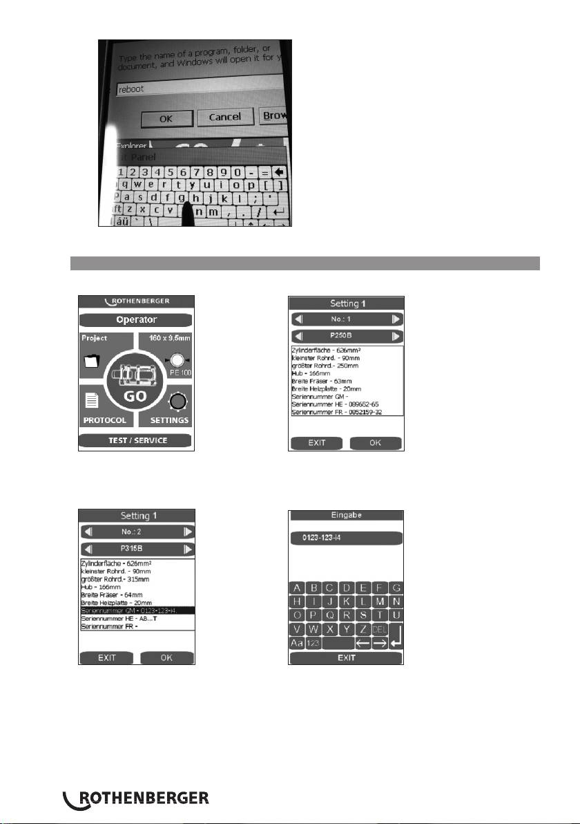
Auf erscheinender Tastatur reboot eingeben und „OK“ drücken, der PC startet neu.
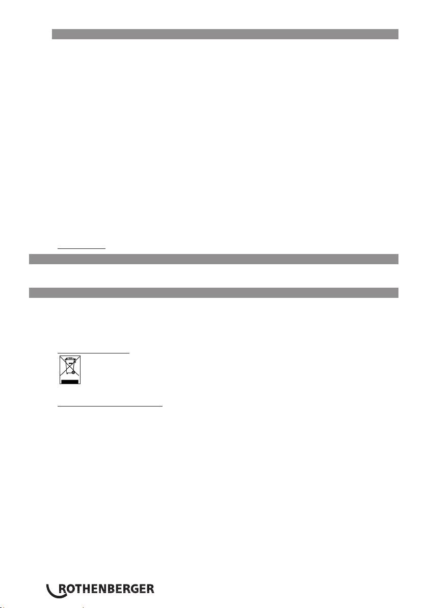
3.7 Maschinenkonfigurationen anlegen- auswählen
Um Maschinenkonfigurationen auszuwählen oder anzulegen die Taste SETTINGS drücken.
Mit den Pfeiltasten kann die gewünschte Maschinenkonfiguration ausgewählt werden.
Um eine neue Konfiguration anzulegen mit der Pfeiltaste nach rechts die nächste No. z.B. 2
starten.
Durch Druck auf das entsprechende Anzeigefeld erscheint die Eingabemaske. Die Daten können
mit DEL gelöscht und neue eingegeben werden, diese Daten werden später in das Protokoll
übernommen.
DEUTSCH26

3.8 Fehlermeldungen
Touch-PC und Protokoll:
Fehlermeldung Benennung
Code 1 Angleichdruck zu gross
Code 2 Angleichdruck zu klein
Code 4 Anwärmdruck zu gross
Code 64 Umstellzeit zu lang
Code 128 Druckaufbauzeit zu lang
Code 256 Fügedruck zu gross
Code 512 Fügedruck zu klein
Code 2048 Heizelement zu kalt
Code 4096 Abbruch durch Bediener
Code 131072 Heizelement zu warm
Steuerung:
Fehlermeldung Benennung Störungsbeseitigung
SER Servicedatum erreicht,
Service durchführen lassen
Service fällig
ERR1 Absoluter Druck wird nicht
Ölstand prüfen, Drucksensor prüfen,
erreicht
Ventile defekt, Motor defekt
PE-2 Drucksensor -24V defekt Drucksensor tauschen
ERR5 Öltemperatur 70°C – Stop! Warten bis Öltemperatur unter 50°C
HE-1 Heizelement nicht
Fühler austauschen
angeschlossen, Fühlerbruch
HE-0 Heizelement zu warm Temperatur nachmessen, Einstellung
kontrollieren, Fühler austauschen
HE-2 Heizelement zu kalt Temperatur nachmessen, Einstellung
kontrollieren, Fühler austauschen
4 Pflege und Wartung
Zur Erhaltung der Funktionsfähigkeit der Maschine sind folgende Punkte zu beachten:
• Die Führungsstangen müssen frei von Schmutz gehalten werden. Bei Beschädigungen an der
Oberfläche sind die Führungsstangen auszutauschen, da dies evtl. zu Druckverlust führen
kann.
• Um einwandfreie Schweißergebnisse zu erhalten, ist es notwendig, das Heizelement sauber
zuhalten. Bei Beschädigungen der Oberfläche muss das Heizelement neu beschichtet bzw.
ausgetauscht werden. Materialrückstände auf dem Heizspiegel vermindern die Antihafteigen-
schaften und sollten mit einem nicht fasernden Papier und Spiritus (nur bei kaltem
Heizelement!) entfernt werden.
• Das Hydraulik - Öl (HLP – 46, Art. Nr.: 53649) ist alle 12 Monate zu wechseln.
• Um Funktionsstörungen zu vermeiden, ist das Hydraulikaggregat regelmäßig auf Dichtheit,
festen Sitz der Verschraubungen sowie einwandfreien Zustand des Elektrokabels zu
überprüfen.
• Die Hydraulikschnellkupplung am Hydraulikaggregat und am Schlauchpaket sind vor
Verschmutzung zu schützen. Bei Verschmutzung sind diese vor dem Anschließen zu reinigen.
• Die Fräseinrichtung ist mit zwei doppelseitig angeschliffenen Messern ausgerüstet. Bei
nachlassender Schnittleistung können die Messer gewendet bzw. durch neue ersetzt werden
• Es ist stets darauf zu achten, dass die zu bearbeitenden Rohr – bzw. Werkstückenden,
insbesondere die Stirnflächen, frei von Verschmutzung sind, da sonst die Lebensdauer der
Messer vermindert wird.
Eine jährliche Überprüfung der Schweißmaschine, ist gemäß DVS 2208, durch den
Hersteller oder einer von Ihm autorisierten Service - Station durchführen zu
lassen. Bei Maschinen mit überdurchschnittlicher Belastung sollte der Prüfzyklus
verkürzt werden.
DEUTSCH 27
4.1 Maschinen - und Werkzeugpflege
(Wartungsvorschriften Pkt. 4 beachten!)
Scharfe und saubere Werkzeuge erzeugen bessere Arbeitsergebnisse und sind sicherer.
Stumpfe, zerbrochene oder verlorengegangene Teile unverzüglich auswechseln. Prüfen, ob das
Zubehör sicher mit der Maschine verbunden ist.
Bei Wartungsarbeiten nur Original - Ersatzteile verwenden. Reparaturen dürfen nur durch fachlich
qualifiziertes Personal ausgeführt werden.
Bei Nichtbenutzung, vor Pflege- und Wartungsarbeiten und vor dem Wechseln von
Zubehörteilen, Maschinen vom Stromnetz trennen.
Vor dem Wiederanschluss an das Stromnetz ist sicherzustellen, dass die Maschine und das
Zubehörwerkzeug ausgeschaltet sind.
Bei Verwendung von Verlängerungskabeln sind diese auf ihre Sicherheit und Funktionsfähigkeit
zu prüfen. Es dürfen nur für den Außeneinsatz zugelassene Kabel verwendet werden.
Nicht benutzen darf man Werkzeuge und Maschinen, wenn Gehäuse oder Handgriffe, besonders
solche aus Kunststoff, gerissen bzw. verzogen sind.
Schmutz und Feuchtigkeit in solchen Rissen leiten den elektrischen Strom. Dies kann zu einem
elektrischen Schlag führen, falls im Werkzeug bzw. in der Maschine ein Isolationsschaden auftritt.
Anmerkung: Weiterhin verweisen wir auf die Unfallverhütungsvorschriften.
5 Zubehör
Geeignetes Zubehör und ein Bestellformular finden Sie ab Seite 451.
6 Entsorgung
Teile des Gerätes sind Wertstoffe und können der Wiederverwertung zugeführt werden. Hierfür
stehen zugelassene und zertifizierte Verwerterbetriebe zur Verfügung. Zur umweltverträglichen
Entsorgung der nicht verwertbaren Teile (z.B. Elektronikschrott) befragen Sie bitte Ihre zuständige
Abfallbehörde.
Nur für EU-Länder:
Werfen Sie Elektrowerkzeuge nicht in den Hausmüll! Gemäß der Europäischen Richtlinie
2012/19/EU über Elektro- und Elektronik-Altgeräte und ihrer Umsetzung in nationales
Recht müssen nicht mehr gebrauchsfähige Elektrowerkzeuge getrennt gesammelt und
einer umweltgerechten Wiederverwertung zugeführt werden.
Nur für Deutschland gültig:
Die Entsorgung Ihres erworbenen ROTHENBERGER Gerätes übernimmt ROTHENBERGER für
Sie - kostenlos! Bitte geben Sie dies bei Ihrem nächsten ROTHENBERGER Service Express Händler
ab. Wer Ihr ROTHENBERGER Service Express Händler in Ihrer Nähe ist, erfahren Sie auf unserer
Homepage unter www.rothenberger.com
DEUTSCH28

Contens Page
1 Safety Instructions 30
1.1 Proper usage 30
1.2 General safety rules 30
2 Technical data, see booklet „technical data“
3 Equipment function 32
3.1 Description 32
3.1.1 Basic unit (fig. A) 32
3.1.2 Hydraulic unit (fig. B) 32
3.2 Operating instructions 33
3.2.1 Putting into operation 33
3.2.2 Welding preparations 36
3.2.3 Welding 39
3.2.4 Welding in premium mode 43
3.2.4.1 Welding process in premium mode 45
3.2.5 Putting out of operation 48
3.3 General requirements 49
3.4 Important information on welding parameters 49
3.5 Setting parameters 49
3.6 Set date and time 50
3.7 Setting up or selecting machine configurations 52
3.8 Error messages 53
4 Care and maintenance 53
4.1 Machine and tool care 54
5 Accessories 54
6 Disposal 54
Markings in this document:
Danger!
This sign warns against the danger of personal injuries.
Caution!
This sign warns against the danger of property damage and damage to the
environment.
Call for action
ENGLISH 29

1 Safety Instructions
1.1 Proper usage
ROWELD P250-630/8-24B Plus Premium CNC models are only to be used for producing
welded joints on PE, PP and PVDF tubes according to the technical data.
1.2 General safety rules
ATTENTION! When using electric tools, the following fundamental safety measures must
be taken to prevent electric shock, injury or fire.
Read all of these instructions before you use the electric tool, and store the safety
instructions properly.
Service and maintenance:
1 Regular cleaning, maintenance and lubrication. Always pull the electrical plug before any
adjustment, maintenance or repair.
2 Have your device repaired only by qualified experts and only with original
replacement parts. This ensures the continued safety of the device.
Working safely:
1 Keep your work area orderly. A messy work area can cause accidents.
2 Consider environmental influences. Do not expose electric tools to rain. Do not use
electric tools in damp or wet environments. Keep the work area well lit. Do not use electric
tools where there is a risk of fire or explosion.
3 Protect yourself from electric shock. Avoid physical contact with earthed parts (such as
pipes, radiators, electric stoves or cooling devices).
4 Keep other people away. Do not let other people — especially children — touch the
electric tool or its cable. Keep them clear of the work area.
5 Store electric tools safely when they are not in use. Unused electric tools should be kept
in a dry, high or closed area, out of reach of children.
6 Do not overload your electric tool. Work is better and safer within the performance range
indicated.
7 Use the right electric tool. Don’t use low-performance machines for heavy-duty jobs. Do
not use the electric tool for purposes for which it was not intended. For example, do not use
a portable circular saw for cutting tree branches or logs.
8 Wear proper clothing. Do not wear loose clothing or jewellery, as they can get caught in
moving parts. When working outdoors, wear slip-resistant shoes. Wear a hairnet over long
hair.
9 Use protective gear. Wear safety glasses. Wear a breathing mask during work that creates
dust.
10 Connect the dust extraction equipment. If there are connections to dust extraction and
collection equipment, make sure that they are connected and properly used.
11 Do not use the cable for purposes for which it was not intended. Never use the cable
to pull the plug from the socket. Protect the cable from heat, oil and sharp edges.
12 Secure the work piece. Use clamps or a vice to hold the work piece firmly. They will hold it
more securely than your hand can.
13 Avoid abnormal postures. Make sure to stand securely and always keep your balance.
ENGLISH30

14 Maintain your tools with care. For better and safer work, keep cutting tools sharp and
clean. Follow the instructions for lubrication and changing tools. Regularly inspect the electric
tool’s connection cable, and if it is damaged, have it replaced by an authorized expert.
Regularly check extension cords, and replace them if they are damaged. Keep the handles dry,
clean and free of oil and grease.
15 Pull the plug from the socket. When not using the electric tool, before maintenance or
when changing tools, such as saw blades, drills and cutting bits.
16 Do not leave any tool keys inserted. Before switching on, check to see that keys and
adjustment tools have been removed.
17 Avoid unintentional activation. When plugging the tool in, make sure that the switch is
turned off.
18 Use outdoor extension cords. When outdoors, use only extension cords that are approved
and appropriately marked.
19 Be alert. Pay attention to what you do. Approach your work sensibly. Do not use the electric
tool when you are distracted.
20 Check the electric tool for damage. Before using the electric tool, you must inspect safety
equipment or slightly damaged parts carefully to ensure that they work properly and as
intended. Check to see that the moving parts operate freely and don’t stick, and to make
sure no parts are damaged. All parts must be mounted properly and meet all the conditions
for ensuring trouble-free operation of the electric tool.
Damaged safety equipment and parts must be properly repaired or replaced by a professional
facility, unless otherwise indicated in the user manual. Damaged switches must be replaced
by a customer service facility.
Never use an electric tool whose switch cannot be turned on and off.
21 Caution. Using other insertion tools and accessories may cause injury.
22 Have your tool repaired by an electrical expert. This electric tool meets applicable safety
requirements. Repairs must be made only by an electrical expert using original replacement
parts. Otherwise accidents many occur.
2 Technical data, see booklet „technical data“
ENGLISH 31

3 Equipment function
3.1 Description
The ROWELD P250-630/8-24B Plus Premium CNCs are compact, transportable heating
element butt welding machines with a CNC module for exact control, maintenance and storing
according to DVS guidelines. They also allow log files to be transferred through a USB connection
specially designed for use on construction sites, and particularly in pipe trenches. Of course, the
tools are very well suited for use in the workshop.
The versatility of the ROWELD welding machines allows the operator to securely join 90-630 mm/
5-24” (outer dimensions) PE, PP and PVDF pipes for all plumbing and sanitation applications as
listed below:
I. pipe - pipe
II. pipe - pipe bends
III. pipe - T-joints
IV. pipe - welding neck
The essential machine components are:
basic unit, reduction clamp insets, hydraulic unit with CNC module, trimmer unit, heating plate,
carrying frame.
When joining welding necks always use the flange adapter (optional accessory, must be ordered
separately).
ROWELD P250/8B: When welding pipe bends with a narrow radius of the maximum diameter of
the machine, this bevelled upper clamping tool should be used as an accessory.
ROWELD P500-630/18-24B Plus: To insert and remove the trimmer and the heating plate we
recommend using the electrical hoist (optional accessory, must be ordered separately).
3.1.1 Basic unit (fig. A)
1 Movable clamps 3 Spacer with locking notch
2 Sliding clamps 4 Heating element take-off device
3.1.2 Hydraulic unit (fig. B)
1 Automatic button 12 Timer button
2 Pressure button 13 Socket for cutting unit
3 Pressure release button 14 Quick coupling for pipe collar
4 Adjusting knob 15 Quick coupling for plug
5 Cutting button 16 Heating element connector
6 ON/OFF button 17 Electrical plug
7 Heating button 18 Emergency OFF
8 "Open" machine 19 Touch screen PC
9 Temperature and time display 20 Oil filling port with dipstick
10 Release button 21 USB connection
11 "Close" machine 22 Basic machine plug and socket device
The hydraulic unit allows the operator to operate the welding machine and perform the functions
indicated by the following symbols:
Turning the hydraulic assembly on and off
Press the „Heating“ button to turn the heating element on. Set the desi-
red heating element temperature by pressing the „Heating“ button and
turning the adjustment knob. The value will be shown in the temperature
display, and then the current value is again shown.
ENGLISH32
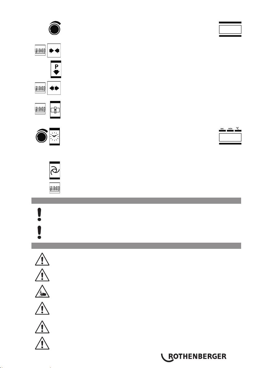
Use the adjustment knob to set the pressure for cutting, aligning, heating
and joining.The value is shown in the „Pressure“ display. Three seconds
after the settings are made, the current value is shown. Pressing the rotary
knob displays and allows changes to be made to the service parameters
.
To bring the clamping elements together, press the release button and „close“ the
machine.
Pressure release button
To separate the clamping elements, press the release button and „open“ the
machine.
Press the release button and the cutting button to turn on the cutting unit socket.
Pressure is automatically set to 10 bar and can be increased to a maximum of 20 bar
using the adjusting knob. (In special situations, such as on slopes, the pressure can
be set to a maximum of 50 bar by changing P004.)
Activate the timer by pressing it once. By pressing the button and turning
the adjusting knob, the t1 time can be set in seconds. Pressing the button
longer switches over to t4. By pressing the button and turning the adju-
sting knob, the t4 time can be set in minutes. The timer is started manu-
ally by shortly pressing on the timer key if the timer indicator lights up
with t1 or t2.
Pressing the Automatic button allows the set pressure to be monitored and
regulated, if necessary, during warming up (timer t1 active) and the joining process
(timer t4 active).
Release button for actuating the service parameter
3.2 Operating instructions
In accordance with national or EU ordinances and guidelines, e. g. DVS 2212,
Section I, only duly qualified and authorised personnel are allowed to operate the
ROWELD welding machines!
Only trained and authorised welders are allowed to operate the machine!
3.2.1 Putting into operation
Please read through the operating instructions and safety instructions attentively
before you put the butt fusion welding machine into operation!
Do not use the heating element in explosive environments or bring it into contact
with easily flammable materials.
Stay a safe distance away from the machine. Do not stand or reach into the
machine. Keep other people away from the work area.
Before every start-up, check the oil level of the hydraulic unit. The oil level must
be between the min. and max. marking on dipstick in the oil filler cap (20). If
necessary, add HLP 46 hydraulic oil.
Transport and set the hydraulic unit only in a horizontal position. If it is set at an
angle, oil escapes from the vented plugs with the dipstick.
If there is a hazard, press the emergency OFF switch (18). Before each start-up,
make sure that the emergency OFF is not locked!
ENGLISH 33
Connect the two hydraulic hoses to the basic machine using the quick coupling (14,15) on
the hydraulic unit.
Protect the quick couplings from contamination. Replace leaky couplings
immediately!
Connect milling unit mains plug to socket (13), heating element plug to plug and socket
device (16), and basic machine plug to plug and socket device (22).
Connect the electrical plug of the hydraulic unit (17) to the power supply according to the
model plate. If the start screen does not appear, unlock the emergency OFF switch. A signal
tone will sound, and a dot will light up on the display (2).
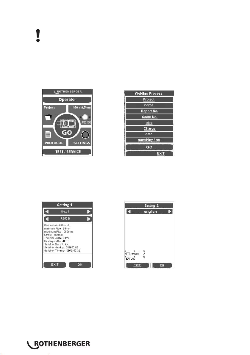
Upon first use, check the date and time. To do this, press the GO button. (To change, see
point 3.6) . To close the menu, press EXIT.
If you press GO key and no basic machine is connected, the following message appears:
„Attention! No basic machine is detected. Please connect.“
If the error message still appears after connection, then the connection is defect, but there is
the possibility to weld and log in premium mode (see 3.2.4).
During first use, set the language. German is set by default. To change the settings, press and
change using OK in Setting 2.
Use the arrow keys to select the desired language and press OK to confirm. The selected
language will be saved after the first welding process.
It is possible to switch the screen to standby mode. The screen saver becomes active when
the hydraulic unit is shut off with the button (6).
Turn the hydraulic unit on (press button (6)).
After it is switched on, the heating element warms up.
The current temperature is shown on the display (9). The control is active when a dot
lights up on the display. When the set temperature is reached, the two LEDs (current and
target) light up. After another 10 minutes, the heating element is ready to use. Check the
temperature with a temperature measurement device.
ENGLISH34
To adjust the temperature of the heating element, see point 3.5.
Risk of serious injury! The heating plate can reach temperatures of over 300°C
(575°F)! We highly recommend storing the heating plate in the designated
carrying frame immediately after use!
Pressing longer on the button (7) shuts off the heat. The dot on the display (9) goes off.
Pressing again turns the heat back on.
ROWELD P500-630/18-24B Plus hydraulic unit: Check the direction of rotation! The
machines are clamped to turn clockwise at the factory. Open and close the machine with the
hydraulic unit. If there is no movement, use an appropriate tool to switch the phase inverter
on the electrical plug.
Note: Do not turn the hydraulic unit on if the direction of rotation is wrong (this may destroy
it).
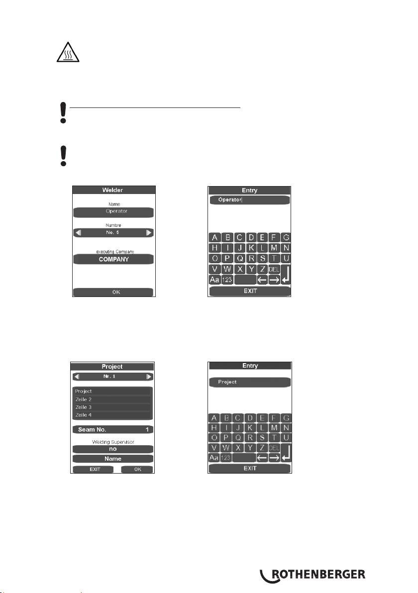
Enter or select the welder name „Operator“.
In the entry form, saved welders can be selected, new welder names can be entered, and
existing welder names can be deleted with DEL and reentered. All entry forms are confirmed
and saved with the ENTER or OK button, and the next program step is called up. The EXIT
button closes the entry form without saving it.
Enter or select a project.
The entry forms can be used to select saved projects or enter new project names. Close and
save using the ENTER key.
Select a pipe.
ENGLISH 35
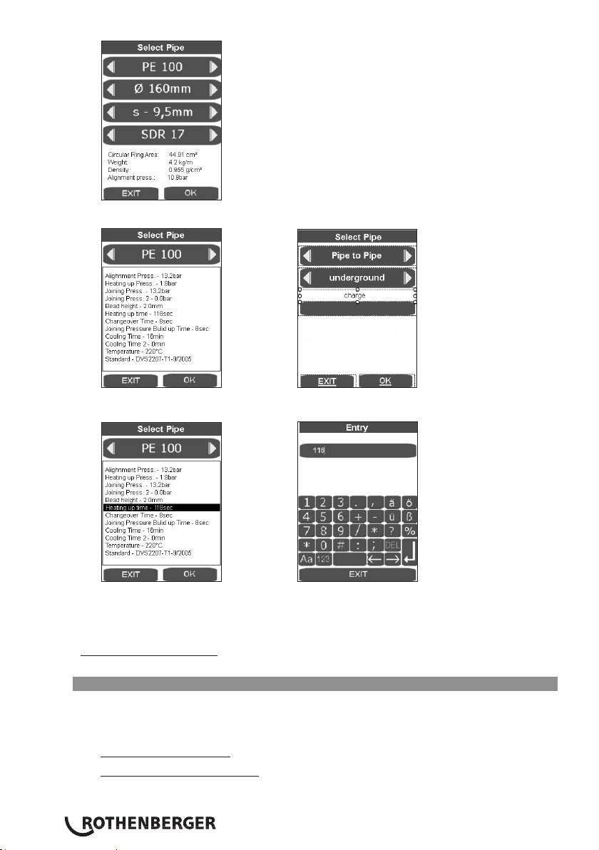
Use the arrow keys to select the desired pipe and press OK to confirm.
In this final overview of the pipe parameters, the pipe data are shown according to DVS
guidelines. Press OK to show the window for the welding parts and laying system.
Non-standard modifications can be made by pressing the relevant display field and pressing
ENTER to save. In the Standard point, the description then changes. This can be entered into
the comments field later before printing out the log on the computer. After the pipe data
have been confirmed and saved by pressing OK, the main menu appears.
For P500-630/18-24B Plus: For lifting the milling equipment and the heating element, use lifting
device 53410 (P500/18B) or 53323 (P630/24B/P630/24B Plus), or a suitable tool.
3.2.2 Welding preparations
Pipes smaller than the maximum welding range (diameter) of the machine, mount the
adapter clamping inserts suited for the pipe diameter with the Allen screws found in the
accessories kit.
ROWELD P250-355/8-12B: consisting of six wide-surface shells and two small-surface shells
ROWELD P500-630/18-24B Plus: consisting of six wide-surface shells and two small-surface
shells (for diameters up to 450 mm) or 8 wide-surface shells (for
diameters >500 mm).
ENGLISH36
In so doing, please observe that the small-surface shells are mounted to the two lower
external main clamps. These are used in the left basic clamping element below and above
only for pipe to pipe bend connections.
Insert the plastic pipe or fitting in the clamping device (use dolly with longer pipe < 2,5m
sections) and tighten brass nut on the upper clamps. Adjust brass nuts (tighten or loosen) to
compensate for any ovalness.
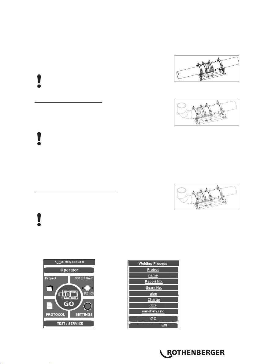
For pipe-to-pipe connections, the two spacers must be
engaged in both left clamping elements (standard
configuration at delivery).
Attention: Under no circumstances should the spacers be
installed diagonally offset!
The pipes are each held by two clamping elements.
Pipe / Fitting P250-355/8-12B:
For pipe-to-fitting connections, the two spacers must be
engaged in both middle clamping elements, and the heating
element take-off device is suspended into the left clamping
elements.
Attention: Under no circumstances should the spacers be installed diagonally offset!
The pipe is inserted into three clamping elements, and the fitting is held by one clamping
element. Thus, the movable clamping element can be shifted on the rod as space
requirements demand during clamping.
When some fittings are being processed in certain positions, such as horizontal bends or
welding necks, it is necessary to remove the heating element take-off device.
Pipe / Fitting P500-630/18-24B Plus:
For pipe-to-fitting connections, the spacers must be swivelled
to the other side and engaged in the middle clamping
elements.
Attention: Under no circumstances should the spacers be installed diagonally offset!
The pipe is inserted into three clamping elements, and the fitting is held by one clamping
element. Thus, the movable clamping element can be shifted on the rod as space
requirements demand during clamping.
Start the welding process with GO.
In this final overview, the last changes can be made by clicking on the relevant subpoint and
confirming with GO.
ENGLISH 37
In CNC mode, control is executed by the touch PC. All functions outside the touch PC, except
for the power key (6), are blocked.
The welding process can be cancelled by the power key. The key lock is then raised and the
relevant message appears in the display.
Pressing the arrow key causes the machine to start up; pressing EXIT causes the programme
to spring into the main menu without saving.
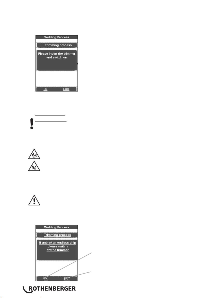
Place the electrical cutting unit between the two work pieces to be welded.
P250-355/8-12B: Switch on the miller motor and lock the switch in place.
P500B-630B Plus: Verify the direction of rotation! The machines were polarised to
turn clockwise before leaving our factory!
Switch on the milling unit by pressing the text field. The cutting disks must run in the cutting
direction. If they don‘t, use an appropriate tool to switch the phase inverter on the electrical
plug.
Risk of serious injury! During operation trimmer unit, stay a safe distance away
from the machine, and do not reach into the rotating knife. Use trimmer in
working position only and return it into the designated carrying frame
immediately after use. Ensure that the safety switch functions properly at all
times to avoid any accidental starting of the trimmer away from the basic
machine.
Clamping elements move together automatically. The cutting pressure can be increased with
the rotary knob (4). Standard cutting pressure is up to 20 bar, but it can be raised to 50 bar,
see point 3.5.
An excessively high milling pressure can lead to overheating and damage to the
miller drive. When the milling drive is overloaded or at rest, raise the machine
and reduce the pressure (s. 3.5).
After the shavings with a chip thickness of < = 0.2mm are discharged continuously from the
milling cutter, press on text field. Milling unit is switched off and the clamping elements start
up.
The arrow keys take the program back to „Please
insert the trimmer...“
EXIT takes the program to the main menu without
saving.
ENGLISH38
