Rothenberger RODIACUT 400 PRO D: инструкция
Раздел: Техника
Тип:
Инструкция к Rothenberger RODIACUT 400 PRO D
RODIACUT 400 PRO
RODIACUT 400 PRO
Bedienungsanleitung
Instructions for use
Instruction d’utilisation
Instrucciones de uso
Istruzioni d’uso
Gebruiksaanwijzing
Instruções de serviço
Brugsanvisning
Bruksanvisning
Bruksanvisning
Käyttöohje
Instrukcja obslugi
FF30030
Návod k používání
Kullanim kilavuzu
Kezelési útmutató
Navodilo za uporabo
èíñòðóêöèÿ çà åêñïëîàòàöèÿ
Ïäçãßåò ÷ñÞóåùò
Èíñòðóêöèÿ ïî èñïîëüçîâàíèþ
www.rothenberger.com
A
Overview
9
8
2
4
3
7
11
12
10
6
15
B
Start up
FF35120
FF35121
FF35120
FF35120
1
FF35121
FF35121
FF35120 = Ø15 x 65mm
FF35121 = Ø20 x 85mm
2 3

Intro
CE-KONFORMITÄTSERKLÄRUNG
TODISTUS CE-STANDARDINMUKAISUUDESTA
Wir erklären in alleiniger Verantwortung, dass
Todistamme täten ja vastaamme yksin siitä, että
dieses Produkt mit den angegebenen Normen
tämä tuote on allalueteltujen standardien ja
und Richtlinien übereinstimmt.
standardoimisasiakirjojen vaatimusten mukainen.
EC-DECLARATION OF CONFORMITY
DEKLARACJA ZGODNOŒCI CE
We declare on our sole accountability that this
Oœwiadczamy z pe³n¹ odpowiedzialnoœci¹, ¿e
product conforms to the standards and guidelines
produkt ten odpowiada wymaganiom nastêpuj¹cych
stated.
norm i dokumentów normatywnych.
DECLARATION CE DE CONFORMITÉ
CE-PROHLÁŠENÍ O SHODÌ
Nous déclarons sous notre propre responsabilité
Se vší zodpovìdností prohlašujeme, že tento výrobek
que ce produit est conforme aux normes et
odpovídá následujícím normám a normativním
directives indiquées.
dokumentùm.
DECLARACION DE CONFORMIDAD CE
CE UYGUNLUK BEYANI
Declaramos, bajo nuestra responsabilidad
Tek sorumlu olarak bu ürünün yönetmelik hükümleri
exclusiva, que este producto cumple con las
uyarýnca aþaðýdaki normlara ve norm
normas y directivas mencionadas.
dokümanlarýna uygunluðunu beyan ederiz.
DICHARAZIONE DI CONFORMITÀ CE
CE-AZONOSSÁGI NYILATKOZAT
Dichiariamo su nostra unica responsabilità, che
Teljes felelõsségünk tudatában kijelentjük, hogy jelen
questo prodotto è conforme alle norme ed alle
termék megfelel a következõ szabványoknak vagy
direttive indicate.
szabványossági dokumentumoknak.
EC-KONFORMITEITSVERKLARING
CE IZJAVA O SKLADNOSTI
Wij verklaren in eigen verantwoordelijkheid dat
V lastni odgovornosti izjavljamo, da je ta izdelek
dit product overeenstemt met de van toepassing
skladen z navedenimi normami in direktivami.
zijnde normen en richtlijnen.
ÄÅÊËÀÐÀÖÈŸ ÇÀ ÑÚÎÒÂÅÒÑÒÂÈÅ
DECLARAÇÃO DE CONFORMIDADE CE
Íèå íàé-îòãîâîðíî äåêëàðèðàìå, ÷å òîçè
Declaramos, sob responsabilidade exclusiva, que
ïðîäóêò ñúîòâåòñòâà íà çàäàäåíèòå íîðìè è
o presente produto está conforme com as Normas
ïðåäïèñàíèÿ
e Directivas indicadas.
ÄÇËÙÓÇ ÐÉÓÔÏÔÇÔÁÓ ÅÊ
ÄÞëþíïõìå ìå áðïêëåéóôéêÞ ìáò åõèývç, üôé áõôü
CE-KONFORMITETSERKLÆRING
ôï ðñïúüv ávôáðïêñßvåôáé óôá áêüëïõèá ðñüôõðá
Vi erklærer som eneansvarlig, at dette produkt er
Þ Ýããñáöá ôõðïðïßçóçò.
i overensstemmelse med anførte standarder,
retningslinjer og direktiver.
ÄÅÊËÀÐÀÖÈß Î ÑÎÎÒÂÅÒÑÒÂÈÈ
ÑÒÀÍÄÀÐÒÀÌ EÑ
CE-FÖRSÄKRAN
Ìû çàÿâëÿåì ÷òî ýòîò ïðîäóêò ñîîòâåòñòâóåò
Vi försäkrar på eget ansvar att denna produkt
ñëåäóþùèì ñòàíäàðòàì
uppfyller de angivna normerna och riktlinjerna.
CE-SAMSVARSERKLÆRING
2006/42/ EG;
Vi erklærer på eget ansvar at dette produktet
EN ISO 12100;
stemmer overens med de følgende normer eller
EN 614; GS-STE/13
normative dokumenter.
ppa. Arnd Greding
17.10.2008
1

Intro
DEUTSCH
Seite 3
Bedienungsanleitung bitte lesen und aufbewahren! Nicht wegwerfen!
Bei Schäden durch Bedienungsfehler erlischt die Garantie! Technische Änderungen vorbehalten!
ENGLISH
page 10
Please read and retain these directions for use. Do not throw them away! The warranty does not cover
damage caused by incorrect use of the equipment! Subject to technical modifications!
FRANÇAIS
page 17
Lire attentivement le mode d’emploi et le ranger à un endroit sûr! Ne pas le jeter ! La garantie est
annulée lors de dommages dûs à une manipulation erronée ! Sous réserve de modifications techniques!
ESPAÑOL
página 24
¡Por favor, lea y conserve el manual de instrucciones! ¡No lo tire! ¡En caso de daños por errores de
manejo, la garantía queda sin validez! Modificaciones técnicas reservadas!
ITALIANO
pagina 31
Per favore leggere e conservare le istruzioni per l´uso! Non gettarle via! In caso di danni dovuti ad errori
nell´uso, la garanzia si estingue! Ci si riservano modifiche tecniche!
NEDERLANDS
bladzijde 38
Lees de handleiding zorgvuldig door en bewaar haar goed! Niet weggooien! Bij schade door
bedieningsfouten komt de garantieverlening te vervallen! Technische wijzigingen voorbehouden!
PORTUGUES
pagina 45
Queiram ler e guardar o manual de instruções! Não deitar fora! Em caso de avarias por utilização
incorrecta, extingue-se a garantia! Reservado o direito de alterações técnicas!
DANSK
side 52
Læs betjeningsvejledningen, og gem den til senere brug! Smid den ikke ud! Skader, som måtte opstå som
følge af betjeningsfejl, medfører, at garantien mister sin gyldighed! Ret til tekniske ændringer forbeholdes!
SVENSKA
sida 59
Läs igenom bruksanvisningen och förvara den väl! Kasta inte bort den! Garantin upphör om apparaten
har använts eller betjänats på ett felaktigt sätt! Med reservation för tekniska ändringar!
NORSK
side 66
Les bruksanvisningen og oppbevar den vel! Ikke kast den! Oppstår skader på grunn av betjeningsfeil
opphører garantiens gyldighet! Tekniske forandringer forbeholdes!
SUOMI
sivulta 73
Lue ja säilytä tämä käyttöohje! Älä heitä pois!
Takuu ei kata käyttövirheistä aiheutuvia vahinkoja! Oikeudet teknisiin muutoksiin pidätetään!
POLSKI
strony 80
Instrukcjê obslugi prosze przeczytac i przechowac! Nie wyrzucac!
Przy uszkodzeniach wynikajacych z blêdów obslugi wygasa gwarancja! Zmiany techniczne zastrzezone!
CESKY
Stránky 87
Návod k obsluze si prosím prectete a uschovejte jej! Nevyhazujte jej!
V prípade poškození zpusobeném chybnou obsluhou zaniká záruka! Technické zmeny jsou vyhrazeny!
TÜRKÇE
sayfa 94
Kullanim açiklamalarini lütfen dikkatlice okuyunuz ve bir yerde muhafaza ediniz! Çöpe atmayiniz!
Kullaniminda yapilan hatalar, garantinin silinmesine neden olur! Teknik deðiþiklikler yapma hakkimiz saklidir!
MAGYAR
oldaltól 101
Kérjük, olvassa el és õrizze meg a kezelési utasítást! Ne dobja el!
A helytelen kezelésbõl származó károsodások esetén megszûnik a jótállás! Mûszaki változtatások fenntartva!
SLOVENŠÈINA
Stran 108
Prosimo preberite in shranite navodilo za uporabo! Ne zavrzite ga!
Pri škodi zaradi napak pri upravljanju ugasne garancija! Pridržujemo si pravico do tehnicnih sprememb!
ÁÚËÃÀÐÑÊÈ
Ñòðàíèöà 115
Ïðî÷åòåòå âíèìàòåëíî è çàïàçåòå èíñòðóêöèÿòà çà åêñïëîàòàöèÿ! Íå ÿ çàõâúðëÿéòå èëè óíèùîæàâàéòå! Ïðè íàñòúïèëè äåôåêòè âñëåäñòâèå
íà íåïðàâèëíî îáñëóæâàíå ãàðàíöèÿòà îòïàäà! Òåõíè÷åñêè èçìåíåíèÿ ïî óðåäà ñà èçêëþ÷èòåëíî â êîìïåòåíöèÿòà íà ôèðìàòà ïðîèçâîäèòåë!
ÅËËÇÍÉÊÁ
122Óåëßäá
Ïäçãßåò ÷åéñéóìïý ðáñáêáëåßóèå íá ôéò äéáâÜóåôå êáé íá ôéò öõëÜóóåôå! Ìçí ôéò ðåôÜîåôå!
Óå æçìéåò áðü óöÜëìáôá ÷åéñéóìïý ðáõåé íá éó÷ýåé ç åããýçóç! Ìå åðéöýëáîç ãéá ôå÷íéêÝò áëëáãÝò!
PÓCCKÈÉ
Ñòðàíèöà 129
Ïðî÷òèòå èíñòðóêöèþ ïî ýêñïëóàòàöèè è ñîõðàíÿéòå å¸ äëÿ äàëüíåéøåãî èñïîëüçîâàíèÿ! B ñëó÷àå ïîëîìêè èíñòðóìåíòà
èç-çà íåñîáëþäåíèÿ èíñòðóêöèè êëèåíò òåðÿåò ïðàâî íà îáñëóæèâàíèå ïî ãàðàíòèè! Bîçìîæíû òåõíè÷åñêèå èçìåíåíèÿ!
2

Inhalt Seite
1 Hinweise zur Sicherheit 4
1.1 Bestimmungsgemäßer Gebrauch 4
1.2 Allgemeine Sicherheitshinweise 4
1.3 Spezielle Sicherheitshinweise 6
2 Technische Daten 6
3 Funktion des Gerätes 6
3.1 Übersicht (Abb. A) 6
3.2 Inbetriebnahme 7
3.3 Befestigungsmöglichkeiten (Abb. B) 7
3.4 Bedienung 8
4 Pflege und Wartung 9
5 Zubehör 9
6 Entsorgung 9
Kennzeichnungen in diesem Dokument
Gefahr
Dieses Zeichen warnt vor Personenschäden.
Achtung
Dieses Zeichen warnt vor Sach- oder Umweltschäden.
Î
Aufforderung zu Handlungen
DEUTSCH 3

1 Hinweise zur Sicherheit
1.1 Bestimmungsgemäßer Gebrauch
Der Kernbohrständer RODIACUT 400 PRO dient ausschließlich zum Bohren von Löchern von 25
bis 400 mm (optional 520mm) Durchmesser in Beton, Stahlbeton, Kunst- und Naturstein und
Mauerwerk mit diamantbestückten Bohrkronen im Nass- oder Trockenbohrverfahren.
Für Arbeiten im oder unter Wasser sind die Bohrständer nicht geeignet. Jede darüber
hinausgehende Verwendung sowie die Nichteinhaltung der Betriebsanleitung und/oder
Wartungsbedienungen gilt nicht als bestimmungsgemäß. Für hieraus resultierende Schäden
haftet der Hersteller nicht.
1.2 Allgemeine Sicherheitshinweise
ACHTUNG! Sämtliche Anweisungen sind zu lesen. Fehler bei der Nichteinhaltung der
nachstehend aufgeführten Anweisungen können elektrischen Schlag, Brand und/oder
schwere Verletzungen verursachen.
Der nachfolgend verwendete Begriff "Elektrowerkzeug" bezieht sich auf netzbetriebene
Elektrowerkzeuge (mit Netzkabel) und auf akkubetriebene Elektrowerkzeuge (ohne Netzkabel).
BEWAHREN SIE DIESE ANWEISUNGEN GUT AUF.
1) Arbeitsplatz
a) Halten Sie Ihren Arbeitsbereich sauber und aufgeräumt. Unordnung und
unbeleuchtete Arbeitsbereiche können zu Unfällen führen.
b) Arbeiten Sie mit dem Gerät nicht in explosionsgefährdeter Umgebung, in der
sich brennbare Flüssigkeiten, Gase oder Stäube befinden. Elektrowerkzeuge
erzeugen Funken, die den Staub oder die Dämpfe entzünden können.
c) Halten Sie Kinder und andere Personen während der Benutzung des Elektro-
werkzeugs fern. Bei Ablenkung können Sie die Kontrolle über das Gerät verlieren.
2) Elektrische Sicherheit
a) Der Anschlussstecker des Gerätes muss in die Steckdose passen. Der Stecker darf
in keiner Weise verändert werden. Verwenden Sie keine Adapterstecker
gemeinsam mit schutzgeerdeten Geräten. Unveränderte Stecker und passende
Steckdosen verringern das Risiko eines elektrischen Schlages.
b) Vermeiden Sie Körperkontakt mit geerdeten Oberflächen, wie von Rohren,
Heizungen, Herden und Kühlschränken. Es besteht ein erhöhtes Risiko durch
elektrischen Schlag, wenn Ihr Körper geerdet ist.
c) Halten Sie das Gerät von Regen oder Nässe fern. Das Eindringen von Wasser in ein
Elektrogerät erhöht das Risiko eines elektrischen Schlages.
d) Zweckentfremden Sie das Kabel nicht, um das Gerät zu tragen, aufzuhängen
oder um den Stecker aus der Steckdose zu ziehen. Halten Sie das Kabel fern von
Hitze, Öl, scharfen Kanten oder sich bewegenden Geräteteilen. Beschädigte oder
verwickelte Kabel erhöhen das Risiko eines elektrischen Schlages.
e) Wenn Sie mit einem Elektrowerkzeug im Freien arbeiten, verwenden Sie nur
Verlängerungskabel, die auch für den Außenbereich zugelassen sind. Die
Anwendung eines für den Außenbereich geeigneten Verlängerungskabels verringert das
Risiko eines elektrischen Schlages.
3) Sicherheit von Personen
a) Seien Sie aufmerksam, achten Sie darauf, was Sie tun, und gehen Sie mit
Vernunft an die Arbeit mit einem Elektrowerkzeug. Benutzen Sie das Gerät nicht,
wenn Sie müde sind oder unter dem Einfluss von Drogen, Alkohol oder
Medikamenten stehen. Ein Moment der Unachtsamkeit beim Gebrauch des Gerätes
kann zu ernsthaften Verletzungen führen.
b) Tragen Sie persönliche Schutzausrüstung und immer eine Schutzbrille. Das Tragen
persönlicher Schutzausrüstung, wie Staubmaske, rutschfeste Sicherheitsschuhe,
4 DEUTSCH

Schutzhelm oder Gehörschutz, je nach Art und Einsatz des Elektrowerkzeuges, verringert
das Risiko von Verletzungen.
c) Vermeiden Sie eine unbeabsichtigte Inbetriebnahme. Vergewissern Sie sich, dass
der Schalter in der Position "AUS" ist, bevor Sie den Stecker in die Steckdose
stecken. Wenn Sie beim Tragen des Gerätes den Finger am Schalter haben oder das
Gerät eingeschaltet an die Stromversorgung anschließen, kann dies zu Unfällen führen.
d) Entfernen Sie Einstellwerkzeuge oder Schraubenschlüssel, bevor Sie das Gerät
einschalten. Ein Werkzeug oder Schlüssel, der sich in einem drehenden Geräteteil
befindet, kann zu Verletzungen führen.
e) Überschätzen Sie sich nicht. Sorgen Sie für einen sicheren Stand und halten Sie
jederzeit das Gleichgewicht. Dadurch können Sie das Gerät in unerwarteten
Situationen besser kontrollieren.
f) Tragen Sie geeignete Kleidung. Tragen Sie keine weite Kleidung oder Schmuck.
Halten Sie Haare, Kleidung und Handschuhe fern von sich bewegenden Teilen.
Lockere Kleidung, Schmuck oder lange Haare können von sich bewegenden Teilen erfasst
werden.
g) Wenn Staubabsaug- und – Auffangeinrichtungen montiert werden können,
vergewissern Sie sich, dass diese angeschlossen sind und richtig verwendet
werden. Das Verwenden dieser Einrichtungen verringert Gefährdungen durch Staub.
4) Sorgfältiger Umgang und Gebrauch von Elektrowerkzeugen
a) Überlasten Sie das Gerät nicht. Verwenden Sie für Ihre Arbeit das dafür
bestimmte Elektrowerkzeug. Mit dem passenden Elektrowerkzeug arbeiten Sie besser
und sicherer im angegebenen Leistungsbereich.
b) Benutzen Sie kein Elektrowerkzeug, dessen Schalter defekt ist. Ein Elektro-
werkzeug, das sich nicht mehr ein- oder ausschalten lässt, ist gefährlich und muss
repariert werden.
c) Ziehen Sie den Stecker aus der Steckdose, bevor Sie Geräteeinstellungen
vornehmen, Zubehörteile wechseln oder das Gerät weglegen. Diese Vorsichts-
maßnahme verhindert den unbeabsichtigten Start des Gerätes.
d) Bewahren Sie unbenutzte Elektrowerkzeuge außerhalb der Reichweite von
Kindern auf. Lassen Sie Personen das Gerät nicht benutzen, die mit diesem nicht
vertraut sind oder diese Anweisungen nicht gelesen haben. Elektrowerkzeuge sind
gefährlich, wenn Sie von unerfahrenen Personen benutzt werden.
e) Pflegen Sie das Gerät mit Sorgfalt. Kontrollieren Sie, ob bewegliche Geräteteile
einwandfrei funktionieren und nicht klemmen, ob Teile gebrochen oder so
beschädigt sind, dass die Funktion des Gerätes beeinträchtigt ist. Lassen Sie
beschädigte Teile vor dem Einsatz des Gerätes reparieren. Viele Unfälle haben ihre
Ursache in schlecht gewarteten Elektrowerkzeugen.
f) Halten Sie Schneidwerkzeuge scharf und sauber. Sorgfältig gepflegte Schneidwerk-
zeuge mit scharfen Schneidkanten verklemmen sich weniger und sind leichter zu führen.
g) Verwenden Sie Elektrowerkzeug, Zubehör, Einsatzwerkzeuge usw. entsprechend
diesen Anweisungen und so, wie es für diesen speziellen Gerätetyp
vorgeschrieben ist. Berücksichtigen Sie dabei die Arbeitsbedingungen und die
auszuführende Tätigkeit. Der Gebrauch von Elektrowerkzeugen für andere als die
vorgesehenen Anwendungen kann zu gefährlichen Situationen führen.
5) Service
Lassen Sie Ihr Gerät nur von qualifiziertem Fachpersonal und nur mit Original-Ersatzteilen
reparieren. Damit wird sichergestellt, dass die Sicherheit des Gerätes erhalten bleibt.
DEUTSCH 5

1.3 Spezielle Sicherheitshinweise
Die mit dem Kernbohrgerät auszuführenden Bohrungen sind ausschließlich vom Bauauftraggeber
festzulegen. Für Schäden an der Statik von Bauwerken und daraus resultierende Folgeschäden
können weder die Mitarbeiter der Firma ROTHENBERGER noch der Anwender haftbar gemacht
werden.
Etwaige Schäden durch Kühlwasser sollten so weit als möglich vorab ausgeschlossen werden. In
Abstimmung mit der Bauleitung müssen erforderliche Gegenmaßnahmen getroffen werden. Für
verdeckte Wasserschäden (Hohlräume, Fugen, Risse, nicht sichtbare Rohre usw.) können weder
die Mitarbeiter der Firma ROTHENBERGER noch der Anwender haftbar gemacht werden.
Lassen Sie bei der Montage des Bohrständers/Bohrmotors keine Werkzeuge stecken!
Verwenden Sie ihre persönliche Schutzausrüstung: Sicherheitsschuhe, Schutzhandschuhe,
Gehörschutz, Staubmaske!
Tragen Sie eng anliegende Kleidung, legen Sie Schmuck ab und binden Sie lange Haare
zusammen oder bedecken Sie diese.
Beim Bohren wird der Geräuschpegel von 90 db überschritten. Es ist daher zwingend
vorgeschrieben, geeignete Gehörschutzmittel zu tragen. Bei Nichtbeachtung kann es zu
erheblichen Gehörschäden kommen!
Während des Bohrens hat der Bediener das Bohrgerät aufmerksam zu beobachten. Bei ersten
Anzeichen für etwaige Störfälle (z.B. Kühlwasserausfall, sich lösender Bohrständer, Blockieren der
Bohrkrone usw.) ist sofort der Motor abzustellen. Erst nach Beseitigung der Ursache darf die
Bohrarbeit fortgesetzt werden.
Kernbohrungen in Decken mit darunter liegenden Räumen stellen ein hohes Sicherheitsrisiko dar.
Nach dem Durchbohren der Decke besteht die Gefahr, dass Bohrkerne herabstürzen. Hier sind
geeignete Gegenmaßnahmen zu treffen (z.B. Bereiche sichern bzw. absperren, Bohrkerne nach
oben entnehmen): BAUSTELLENABSICHERUNG.
2 Technische Daten
Abmessungen LxBxH in mm ....................... 460 x 305 x 1150
Hub............................................................ 680mm
Bohrdurchmesser ....................................... ø 400mm (optional ø 520mm)
Schrägabstützung ...................................... ja
Gewicht .................................................... ca. 21,4 kg
Dübelsetzmaß ............................................ 350mm
3 Funktion des Gerätes
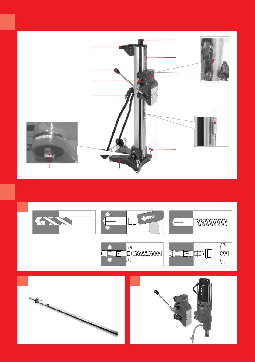
3.1 Übersicht (Abb. A)
1
Fußplatte
7
Feinvorschub 1:3
2
Bohrsäule
8
Handgriff
3
Vorschubeinheit
9
Absprießkopf
4
Vorschubhebel
10
Magnetischer Tiefenanschlag
5
Sechskantmutter
11
Arretierung Vorschubeinheit
6
Ringschrauben
12
Kippklemmhebel
Da das System aus aufeinander abgestimmte Komponenten besteht, verwenden Sie ausschließlich
Original ROTHENBERGER Ersatzteile, Zubehör und Diamantbohrkronen, um jederzeit die optimale
Funktionsfähigkeit des Gerätes zu ermöglichen.
6 DEUTSCH
3.2 Inbetriebnahme
Positionierung:
Auf Position der Ringschrauben (6) achten! Ringschrauben dürfen nicht von der
Unterkante Fußplatte überstehen!
Î Bohrloch vermessen und Bohrlochmitte anzeichnen. Dübelsetzmaß siehe technische
Daten!
Î Fußplatte (1) justieren und befestigen.
Die jeweils optimale Befestigungsmöglichkeit ist von den Gegebenheiten der Baustelle
abhängig. (siehe Befestigungsmöglichkeiten Pkt. 3.3)
Die abschließende Feinausrichtung bzw. Justierung des Bohrständers erreichen Sie durch
Anziehen der vier Ringschrauben (6).
Vor jeder Inbetriebnahme sicherstellen, dass der Bohrständer fest fixiert ist und
nicht wackelt!
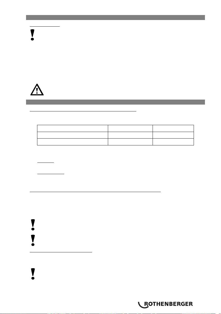
3.3 Befestigungsmöglichkeiten (Abb. B)
Dübelbefestigung in Beton oder Mauerwerk (Bild B-1)
Î Befestigungsloch für Dübelbefestigung vermessen und bohren. Dübelsetzmaß siehe
technische Daten!
Durchmesser in mm Tiefe in mm
Beton (Art. Nr. FF35120) 15 mm 65mm
Mauerwerk (Art. Nr. FF35121) 20mm 85mm
Î Bohrloch sorgfältig vom Bohrmehl säubern.
Î Betondübel mit Spreizkeil bzw. Mauerwerksdübel (bis 5x wieder verwendbar) einsetzen
Betonset:
Kordelgewindestange in Dübel eindrehen, Bohrständer aufsetzen mit U-Scheibe
und Mutter fest anziehen.
Mauerwerkset:
Kordelgewindestange mit Unterlegscheibe und montierter Mutter in den
Anker einschrauben. Mutter mit Gabelschlüssel anziehen. Bohrständer aufsetzen mit U-
Scheibe und Mutter fest anziehen
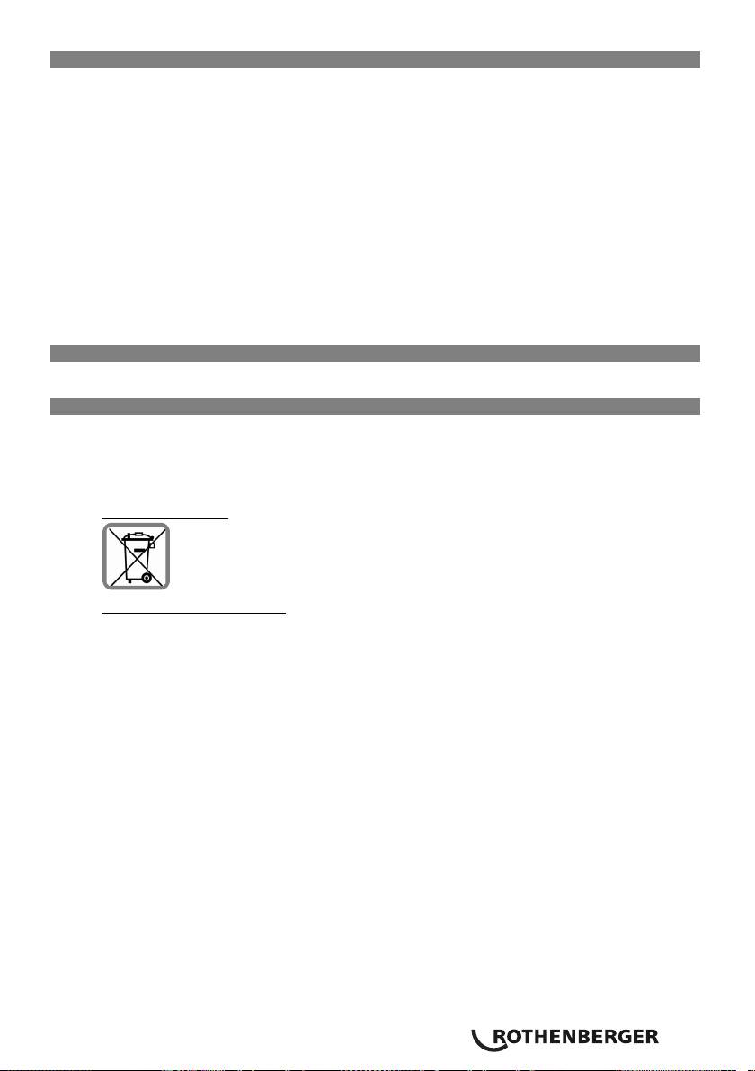
Verspannung mit der Schnellspannsäule (Art. Nr. FF35015 Bild B-2)
Î Bohrständer ausrichten und Schnellspannsäule auf die Fußplatte des Bohrständers aufsetzen.
Î Schnellspannsäule ausfahren und Bohrständer festklemmen.
Mindesthöhe des Raumes: ca. 1,7 m
Max. Höhe des Raumes: ca. 3,0 m
Hinweis: Um Beschädigungen durch die Schnellspannsäule an Decken oder Wänden
vorzubeugen, legen Sie, zur Verteilung des Anpressdruckes auf eine größere Fläche, ein
Stück Holz oder ähnliches zwischen Säulenende und Decke.
Beigefügte Bedienungsanleitung der Schnellspannsäule lesen und verstehen!
Verspannung mit Absprießkopf
Î Geeignetes Distanzstück zwischen Absprießkopf (9) und Wand/Decke setzen.
Î Absprießkopf herausdrehen und somit Bohrständer festklemmen.
Hinweis: Um Beschädigungen durch das Distanzstück an Decken oder Wänden
vorzubeugen, legen Sie, zur Verteilung des Anpressdruckes auf eine größere Fläche, ein Stück
Holz oder ähnliches zwischen Säulenende und Decke.
DEUTSCH 7

3.4 Bedienung
Bohrwinkel einstellen:
Î Sechskantmuttern SW24 (5) und Kippklemmhebel (12) lösen und Bohrsäule (2) auf
gewünschten Winkel (-15 -0- 45°) einstellen.
Î Sechskantmuttern und Kippklemmhebel wieder anziehen.
Beim Festziehen der Sechskantmuttern darauf achten, dass die Verzahnung der
Stützplatte formschlüssig in die Verzahnung der Bohrsäule eingreift!
Diamantbohrmaschine einsetzen (Bild B-3):
Î Arretierung (11) lösen und Vorschubeinheit (3) von Bohrsäule (2) entnehmen
Î Motor mit beiliegenden Schrauben an Vorschubeinheit (3) befestigen.
Auf richtige Lage der Paßfedernut und Bohrungen achten!
Für eine Erweiterung des Bohrbereiches für RODIADRILL 3000 PD können optional zusätzliche
Distanzplatten verwendet werden:
Distanzplatte FF35139
FF35138
20mm
70mm
Bohrkronen Ø 420mm 520mm
Î Vorschubeinheit mit Bohrmotor auf Bohrsäule (2) einschieben und mittels Arretierung (11)
fixieren.
Î Zum Entnehmen in umgekehrter Reihenfolge vorgehen
Magnetischen Tiefenanschlag (10) einstellen:
Î Magnetsichen Tiefenanschlag (10) auf die Verzahnung der Bohrsäule in gewünschter
Bohrtiefe stecken.
Bohrtiefe = Abstand zwischen Unterkante Vorschubgetriebe und Oberkante Tiefenanschlag.
Bohren:
Bedienungsanleitung Bohrmotor lesen und verstehen!
Î Wasserhahn aufdrehen bzw. Staubsauger einschalten.
(Es muss mindestens soviel Wasserdruck (max. 4 bar!) vorhanden sein, dass die anfallenden
Bohrschlämme aus dem Bohrloch gefördert werden)
Î Arretierung (11) Vorschubeinheit lösen und mit Vorschubhebel (4) Bohrmaschine bis zur
gewünschten Bohrtiefe herunterdrehen.
Î Motor ausschalten und Zurückkurbeln, bis die Bohrkrone vollständig sichtbar ist.
Sollte ein Klemmen auftreten, Bohrmotor mit niedriger Drehzahl unter Kühlwasser
wieder anfahren und Bohrkrone zurückziehen!
Notfalls den Vorgang wiederholen bzw. mittels Gabelschlüssel SW 41 an der Bohrkrone
drehen. Achtung: PRCD Schalter ausschalten!
8 DEUTSCH
4 Pflege und Wartung
Arbeiten zur Instandhaltung, Wartung und Pflege dürfen nur im Anlagestillstand durchgeführt
werden.
Die besten Instandhaltungsmaßnahmen sind das tägliche Entfernen von Schlamm, Staub und
Schmutz. Besonderes Augenmerk ist auf Führungssäule und Gleitführung sowie auf Zahnstange
und Vorschubritzel zu legen. Die Spindel sollte nach jeder Reinigung leicht eingeölt werden.
Die Gleitführungen sind in regelmäßigen Abständen auf Spiel zu kontrollieren und bei Bedarf
nachzustellen.
Bohrsäule und Zahnstange nicht fetten, da das Fett mit dem anhaftenden Schmutz wie
eine Schleifpaste wirkt und den Verschleiß erhöht!
Die Stellschrauben der Fußplatte täglich reinigen und leichtgängig halten.
Wichtig! Alle Wartungs-, Instandsetzungs- und Reparaturarbeiten dürfen nur von
eingewiesenem Fachpersonal durchgeführt werden
5 Zubehör
Geeignetes Zubehör und ein Bestellformular finden Sie ab Seite 136.
6 Entsorgung
Teile des Gerätes sind Wertstoffe und können der Wiederverwertung zugeführt werden. Hierfür
stehen zugelassene und zertifizierte Verwerterbetriebe zur Verfügung. Zur umweltverträglichen
Entsorgung der nicht verwertbaren Teile (z.B. Elektronikschrott) befragen Sie bitte Ihre zuständige
Abfallbehörde.
Nur für EU-Länder:
Werfen Sie Elektrowerkzeuge nicht in den Hausmüll! Gemäß der Europäischen
Richtlinie 2002/96/EG über Elektro- und Elektronik-Altgeräte und ihrer Umsetzung in
nationales Recht müssen nicht mehr gebrauchsfähige Elektrowerkzeuge getrennt
gesammelt und einer umweltgerechten Wiederverwertung zugeführt werden.
Nur für Deutschland gültig:
Die Entsorgung Ihres erworbenen ROTHENBERGER Gerätes übernimmt ROTHENBERGER für Sie -
kostenlos! Bitte geben Sie dies bei Ihrem nächsten ROTHENBERGER Service Express Händler ab.
Wer Ihr ROTHENBERGER Service Express Händler in Ihrer Nähe ist, erfahren Sie auf unserer
Homepage unter www.rothenberger.com
DEUTSCH 9

Contens page
1 Safety information 11
1.1 Intended use 11
1.2 General safety rules 11
1.3 Safety information 13
2 Technical data 13
3 Function of the equipment 13
3.1 Overview (ill. A) 13
3.2 Start of operation 14
3.3 Fastening possibilities (ill. B) 14
3.4 Handling 15
4 Care and maintenance 16
5 Accessories 16
6 Disposal 16
Markings in this document
Danger
This sign warns against the danger of personal injuries.
Caution
This sign warns against the danger of property damage and damage to the
environment.
Î
Call for action
10 ENGLISH

1 Safety information
1.1 Intended use
The RODIACUT 400 PRO core drill rig serves exclusively to drill holes of 25 to 400 mm (optional
520mm) in diameter in concrete, reinforced concrete, artificial and natural stone and brickwork
using diamond-equipped core bits for the wet or dry drilling process.
The drill rigs are not suitable for work in or under water. Every application beyond this as well as
failure to comply with the instructions for use and/or maintenance handling shall be regarded as
not in accordance with regulations. The manufacturer shall not be liable for damages as a result
of this.
1.2 General safety rules
WARNING! Read all instructions. Failure to follow all instructions listed below may
result in electric shock, fire and/or serious injury.
The term "power tool" in all of the warnings listed below refers to your mains operated (corded)
power tool or battery operated (cordless) power tool.
SAVE THESE INSTRUCTIONS.
1) Work area
a) Keep work area clean and well lit. Cluttered and dark areas invite accidents.
b) Do not operate power tools in explosive atmospheres, such as in the presence of
flammable liquids, gases or dust. Power tools create sparks which may ignite the dust
or fumes.
c) Keep children and bystanders away while operating a power tool. Distractions can
cause you to lose control.
2) Electrical safety
a) Power tool plugs must match the outlet. Never modify the plug in any way. Do
not use any adapter plugs with earthed (grounded) power tools. Unmodified
plugs and matching outlets will reduce risk of electric shock.
b) Avoid body contact with earthed or grounded surfaces such as pipes, radiators,
ranges and refrigerators. There is an increased risk of electric shock if your body is
earthed or grounded.
c) Do not expose power tools to rain or wet conditions. Water entering a power tool
will increase the risk of electric shock.
d) Do not abuse the cord. Never use the cord for carrying, pulling or unplugging
the power tool. Keep cord away from heat, oil, sharp edges or moving parts.
Damaged or entangled cords increase the risk of electric shock.
e) When operating a power tool outdoors, use an extension cord suitable for
outdoor use. Use of a cord suitable for outdoor use reduces the risk of electric shock.
3) Personal safety
a) Stay alert, watch what you are doing and use common sense when operating a
power tool. Do not use a power tool while you are tired or under the influence
of drugs, alcohol or medication. A moment of in attention while operating power
tools may result in serious personal injury.
b) Use safety equipment. Always wear eye protection. Safety equipment such as dust
mask, nonskid safety shoes, hard hat, or hearing protection used for appropriate
conditions will reduce personal injuries.
c) Avoid accidental starting. Ensure the switch is in the off position before
plugging in. Carrying power tools with your finger on the switch or plugging in power
tools that have the switch on invites accidents.
d) Remove any adjusting key or wrench before turning the power tool on. A wrench
or a key left attached to a rotating part of the power tool may result in personal injury.
ENGLISH 11

e) Do not overreach. Keep proper footing and balance at all times. This enables
better control of the power tool in unexpected situations.
f) Dress properly. Do not wear loose clothing or jewellery. Keep your hair, clothing
and gloves away rom moving parts. Loose clothes, jewellery or long hair can be
caught in moving parts.
g) If devices are provided for the connection of dust extraction and collection
facilities, ensure these are connected and properly used. Use of these devices can
reduce dust related hazards.
4) Power tool use and care
a) Do not force the power tool. Use the correct power tool for your application. The
correct power tool will do the job better and safer at the rate for which it was designed.
b) Do not use the power tool if the switch does not turn it on and off. Any power
tool that cannot be controlled with the switch is dangerous and must be repaired.
c) Disconnect the plug from the power source before making any adjustments,
changing accessories, or storing power tools. Such preventive safety measures
reduce the risk of starting the power tool accidentally.
d) Store idle power tools out of the reach of children and do not allow persons
unfamiliar with the power tool or these instructions to operate the power tool.
Power tools are dangerous in the hands of untrained users.
e) Maintain power tools. Check for misalignment or binding of moving parts,
breakage of parts and any other condition that may affect the power tools
operation. If damaged, have the power tool repaired before use. Many accidents
are caused by poorly maintained power tools.
f) Keep cutting tools sharp and clean. Properly maintained cutting tools with sharp
cutting edges are less likely to bind and are easier to control.
g) Use the power tool, accessories and tool bits etc., in accordance with these
instructions and in the manner intended for the particular type of power tool,
taking into account the working conditions and the work to be performed. Use of
the power tool for operations different from those intended could result in a hazardous
situation.
5) Service
Have your power tool serviced by a qualified repair person using only identical
replacement parts. This will ensure that the safety of the power tool is maintained.
12 ENGLISH

1.3 Safety information
The drilling to be carried out with the core drill must be stipulated exclusively by the construction
customer. Neither the ROTHENBERGER employees nor the user can be held liable for damages to
the construction statics and consequential damages as a result of this.
Any damages due to cooling water must be excluded as far as possible in advance. Necessary
countermeasures must be taken in coordination with construction site management. Neither the
ROTHENBERGER employees nor the user can be held liable for concealed water damages
(cavities, joints, cracks, invisible pipes etc.).
Do not leave any tools inserted during the installation of the drill rig/drill motor.
Use your personal protective equipment: safety shoes, protective gloves, ear protectors, dust
mask.
Wear close-fitting clothing, remove jewellery and tie back or cover long hair.
The 90 dB noise level is exceeded during drilling. It is, therefore, mandatory to wear suitable ear
protection. Non-observance can lead to significant hearing damage.
The operator must observe the drilling equipment attentively during drilling. Shut down the
motor immediately at the first sign of any disturbances (e.g. cooling water deficiency, loosening
of the drill rig, core bit blocked etc.). Drilling work must only be continued after the cause has
been remedied.
Core hole drilling in ceilings with rooms underneath constitutes a high safety risk. After drilling
through the ceiling there is the danger of the drilling cores crashing down. Suitable
countermeasures must be taken (e,g. safeguard or close off areas, remove drilling cores in an
upward direction): SAFEGUARD THE BUILDING SITE.
2 Technical data
Dimensions LxWxH (mm)............................ 460 x 305 x 1150
Drill stroke.................................................. 680mm
Drill diameter max...................................... ø 400mm (optional ø 520mm)
Sloping support.......................................... jes
Weight....................................................... ca. 21,4 kg
Dowel depth extent ................................... 350mm
3 Function of the equipment
3.1 Overview (ill. A)
1
Base plate
7
Fine feed 1:3
2
Drill column
8
Hand grip
3
feed unit
9
Strut head
4
Advance lever
10
Magnetic depth stop
5
Hexagon nut
11
Feeder locking device
6
Eye bolts
12
Rocking clamp lever
As the system consists of coordinated components, please only use original ROTHENBERGER
spare parts, accessories and diamond drill bits in order to enable optimum efficiency of the
equipment at all times.
ENGLISH 13
3.2 Start of operation
Positionierung:
Please pay attention to the position of the ring bolts (6)! Ring bolts must not overlap
the lower edge of the base plate!
Î Measure borehole and mark the centre. See technical data for extent of dowel depth!
Î Adjust and fasten base plate (1).
The respective optimum fastening possibility depends on the building site conditions (see
fastening possibilities, item 3.3)
You can achieve the final fine alignment or adjustment of the drill rig by tightening the four ring
bolts (6).
Every time before start of operation make sure that the drill rig is firmly
fastened and not able to shake!
3.3 Fastening possibilities (ill. B)
Dowel fastening on concrete or brickwork (fig. B-1)
Î Measure and drill a mounting hole for the dowel fastening. See technical data for extent
of dowel depth!
Diameter in mm Depth in mm
Concrete (item no. FF35120) 15 mm 65mm
Brickwork (Art. Nr. FF35121) 20mm 85mm
Î Carefully clean the drill dust from the borehole.
Î Apply the concrete dowel with expansion wedge or brickwork dowel (can be re-used up to 5
times)
Concrete set:
Turn the diamond knurl threaded bar into the dowel, attach the drill rig and
fasten using the U-washer and nut.
Brickwork set:
Screw the diamond knurl threaded bar with the grommet and mounted nut
into the armature. Tighten the nut using an open-ended spanner. Attach the drill rig and
fasten using the U-washer and nut.
Bracing with the quick clamp column (Item no. FF35015 fig. B-2))
Î Align the drill rig and attach the quick clamp column to the base plate of the drill rig.
Î Extend the quick clamp column and clamp the drill rig.
Minimum room height: approx. 1.7 m
Maximum room height: approx. 3.0 m
Information: In order to avoid damage to the ceilings or walls by the quick clamp column,
place a piece of wood or similar between the end of the column and the ceiling to distribute
the contact pressure over a larger area.
Please read and be sure to understand the supplied quick clamp column instruction
manual!
Bracing with the strut head
Î Place a suitable spacer between the strut head (9) and wall/ceiling.
Î Unscrew the strut head and consequently clamp the drill rig.
Note: In order to prevent damages to the ceilings or walls due to the spacer, place a piece of
wood or similar between the end of the column and the ceiling in order to distribute the
contact pressure over a greater area.
14 ENGLISH

3.4 Handling
Setting the drilling angle:
Î Loosen the SW24 hexagon nuts (5) and rocking clamp lever (12) and set the drill column (2)
to the desired angle (-15 -0- 45°).
Î Re-tighten the hexagon nuts and rocking clamp lever.
When tightening the hexagon nuts please ensure that the toothing of the retaining
plate engages positively in the toothing of the drill column.
Applying the diamond drill (fig. B-3):
Î Loosen the locking device (11) and remove the feed unit (3) from the drill column (2).
Î Use the supplied screws to fasten the motor to the feed unit (3).
Please observe the correct position of the feather key groove and the drill holes.
Additional distance plates can be used as an option in order to expand the drilling range for
drill motor RODIADRILL 3000 PD:
Distance plate FF35139
FF35138
20mm
70mm
Drill bits diameter 420mm 520mm
Î Insert the feed unit with the drill motor into the drill column (2) and use the locking device
(11) to fasten.
Î
Proceed in the reverse order in order to remove
Setting the magnetic depth stop (10):
Î Insert the magnetic depth stop (10) into the toothing of the drill column to the desired drill
depth.
Drill depth = distance between bottom edge of the feed gear and top edge of the depth
stop.
Drilling:
Please read and be sure to understand the drill motor instruction manual!
Î Turn on the water tap or switch on the vacuum cleaner.
(There must at least be sufficient water pressure (max. 4 bar!) to move the arising drilling
mud from the borehole)
Î Release the locking device (11) on the feed gear and use the hand wheel (4) to turn the drill
downward to the desired drill depth.
Î Switch off the motor and crank back until the drill bit is completely visible.
In case of seizure, start up the drill motor again at low speed using cooling water
and withdraw the core bit.
In case of need, repeat the process or turn the core bit using the SW 41 flat wrench.
Please note: Switch off the RCD switch!
ENGLISH 15
4 Care and maintenance
Upkeep, servicing and maintenance work must only be carried out when the system is at a
standstill.
The best maintenance measures involve the daily removal of sludge, dust and dirt. Special
attention must be paid to the guide column and sliding guide as well as to the gear rack and the
feed bevel. The spindle should be oiled lightly each time it is cleaned.
The sliding guides should be checked for play at regular intervals and re-adjusted if necessary.
Do not grease the drill column and gear rack as the grease takes effect as a grinding
paste together with the adherent dirt and increases wear.
Clean the adjusting screws on the base plate every day and keep them free-moving.
Important! All maintenance, overhauling and repair work must only be carried out by trained
specialised staff
5 Accessories
The relevant accessories and an order form can be found from Page 136 onwards.
6 Disposal
Components of the unit are recyclable material and should be put to recycling. For this purpose
registered and certified recycling companies are available. For an environmentalfriendly disposal
of the non-recyclable parts (e.g. electronic waste) please contact your local waste disposal
authority.
For EU countries only:
Do not dispose of electric tools with domestic waste. In accordance with European
Directive 2002/96/EC on waste electrical and electronic equipment and its
implementation as national law, electric tools that are no longer serviceable must be
collected separately and utilised for environmentally compatible recycling.
16 ENGLISH
Table des matières Page
1 Consignes de sécurité 18
1.1 Utilisation conforme aux dispositions 18
1.2 Indications générales de sécurité 18
1.3 Consignes de sécurité 20
2 Données techniques 20
3 Fonction de l'appareil 20
3.1 Vue d'ensemble (fig. A) 20
3.2 Mise en service 21
3.3 Possibilités de fixation (fig. B) 21
3.4 Maniement 22
4 Entretien et maintenance 23
5 Accessoires 23
6 Elimination des déchets 23
Pictogrammes contenus dans ce document
Danger
Ce pictogramme signale un risque de blessure pour les personnes.
Attention
Ce pictogramme signale un risque de dommage matériel ou de préjudice pour
l’environnement.
Î
Nécessité d’exécuter une action
FRANÇAIS 17

1 Consignes de sécurité
1.1 Utilisation conforme aux dispositions
Le support de perçage RODIACUT 400 PRO est prévu exclusivement pour le perçage de trous
d'un diamètre de 25 à 400mm (optional 520 mm) dans le béton, le béton armé, la pierre
synthétique et naturelle et la maçonnerie à l'aide de couronnes de perçage diamantées en forage
à l'eau ou à sec.
Les supports de perçage ne conviennent pas à une utilisation dans ou sous l'eau. Toute autre
utilisation ainsi que le non-respect des instructions d'utilisation et / ou des consignes d'entretien
sont considérés comme non conformes à la destination prévue. Le fabricant ne répond pas des
dommages résultant d'une telle utilisation.
1.2 Indications générales de sécurité
ATTENTION ! Lire toutes les indications. Le non-respect des instructions indiquées ci-
après peut entraîner un choc électrique, un incendie et/ou de graves blessures sur les
personnes.
La notion d’« outil électroportatif » mentionnée par la suite se rapporte à des outils électriques
raccordés au secteur (avec câble de raccordement) et à des outils électriques à batterie (sans câble
de raccordement).
GARDER PRECIEUSEMENT CES INSTRUCTIONS DE SECURITE.
1) Place de travail
a) Maintenez l’endroit de travail propre et bien éclairé. Un lieu de travail en désordre
ou mal éclairé augmente le risque d’accidents.
b) N’utilisez pas l’appareil dans un environnement présentant des risques
d’explosion et où se trouvent des liquides, des gaz ou poussières inflammables.
Les outils électroportatifs génèrent des étincelles risquant d’enflammer les poussières ou
les vapeurs.
c) Tenez les enfants et autres personnes éloignés durant l’utilisation de l’outil
électroportatif. En cas d’inattention vous risquez de perdre le contrôle sur l’appareil.
2) Sécurité relative au système électrique
a) La fiche de secteur de l’outil électroportatif doit être appropriée à la prise de
courant. Ne modifiez en aucun cas la fiche. N’utilisez pas de fiches d’adaptateur
avec des appareils avec mise à la terre. Les fiches non modifiées et les prises de
courant appropriées réduisent le risque de choc électrique.
b) Evitez le contact physique avec des surfaces mises à la terre tels que tuyaux,
radiateurs, fours et réfrigérateurs. Il y a un risque élevé de choc électrique au cas où
votre corps serait relié à la terre.
c) N’exposez pas l’outil électroportatif à la pluie ou à l’humidité. La pénétration d’eau
dans un outil électroportatif augmente le risque d’un choc électrique.
d) N’utilisez pas le câble à d’autres fins que celles prévues, n’utilisez pas le câble
pour porter l’appareil ou pour l’accrocher ou encore pour le débrancher de la
prise de courant. Maintenez le câble éloigné des sources de chaleur, des parties
grasses, des bords tranchants ou des parties de l’appareil en rotation. Un câble
endommagé ou torsadé augmente le risque d’un choc électrique.
e) Au cas où vous utiliseriez l’outil électroportatif à l’extérieur, utilisez une rallonge
autorisée homologuée pour les applications extérieures. L’utilisation d’une rallonge
électrique homologue pour les applications extérieures réduit le risque d’un choc
électrique.
3) Sécurité des personnes
a) Restez vigilant, surveillez ce que vous faites. Faites preuve de bon en utilisant
l’outil électroportatif. N’utilisez pas l’appareil lorsque vous êtes fatigué ou après
avoir consommé de l’alcool, des drogues ou avoir pris des médicaments. Un
moment d’inattention lors de l’utilisation de l’appareil peut entraîner de graves blessures
sur les personnes.
18 FRANÇAIS
