Hach-Lange POLYMETRON 9500 Basic User Manual: User interface and navigation
User interface and navigation: Hach-Lange POLYMETRON 9500 Basic User Manual
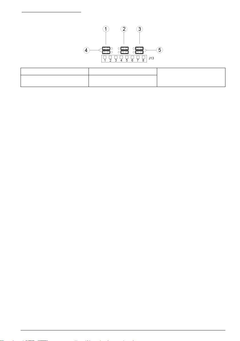
Figure 10 Jumper settings
1 Input 1 configuration jumpers 3 Input 3 configuration jumpers 5 Jumpers positioned to the right
for voltage inputs
2 Input 2 configuration jumpers 4 Jumpers positioned to the left for
switch inputs
1. Open the controller cover.
2. Feed the wires through the cable gland.
3. Adjust the wire as necessary and tighten the cable gland.
4. The jumpers are positioned immediately behind the connector. Remove the connector for
improved access to the jumpers and configure the jumper settings according to the type of input
as shown in Figure 10.
5. Close the controller cover and tighten the cover screws.
6. Configure inputs in the controller.
Note: In switch input mode the controller supplies 12 volts to the switch and is not isolated from the controller. In
voltage input mode the inputs are isolated from the controller (user input voltage from 0 to 30 volts).
Connect the optional digital communication output
The manufacturer supports Modbus RS485, Modbus RS232 and Profibus DPV1 communication
protocols. The optional digital output module is installed in the location indicated by item 4 in Figure 7
on page 12. Refer to the manual supplied with the network module for more details.
For information about Modbus registers, refer to http://www.hach-lange.com or http://www.hach.com.
User interface and navigation
User interface
The keypad has four menu keys and four directional keys as shown in Figure 11.
English
19
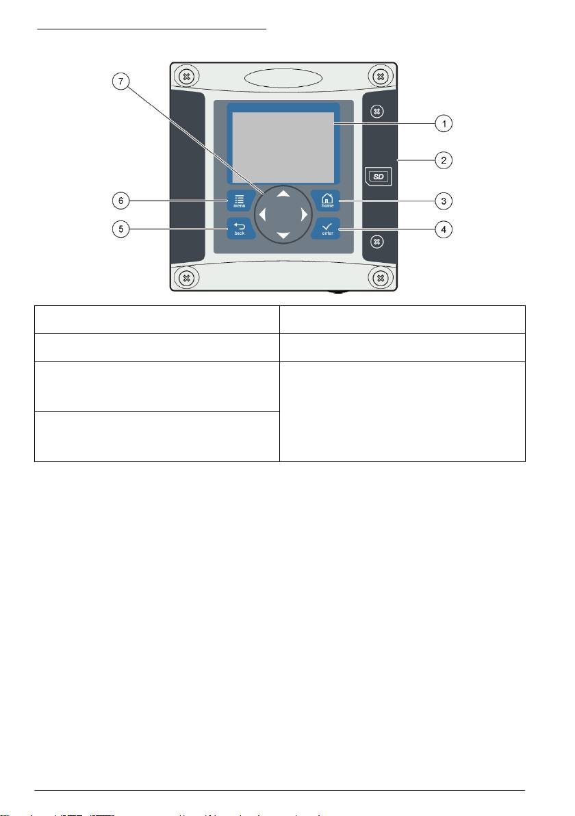
Figure 11 Keypad and front panel overview
1 Instrument display 5 back key. Moves back one level in the menu
structure.
2 Cover for secure digital memory card slot 6 menu key. Moves to the Settings Menu from other
screens and submenus.
3 home key. Moves to the Main Measurement screen
7 Directional keys. Used to navigate through the
from other screens and submenus. On the graphical
measurement screens, menus, change settings,
measurement screen can be used to change the
and increment or decrement digits.
graph settings.
4 enter key. Accepts input values, updates, or
displayed menu options. On the measurement
screen can be used to display diagnostic
information.
Inputs and outputs are set up and configured through the front panel using the keypad and display
screen. This user interface is used to set up and configure inputs and outputs, create log information
and calculated values, and calibrate sensors. The SD interface can be used to save logs and update
software.
Display
Figure 12 shows an example of the main measurement screen with a DO sensor connected to the
controller.
20
English
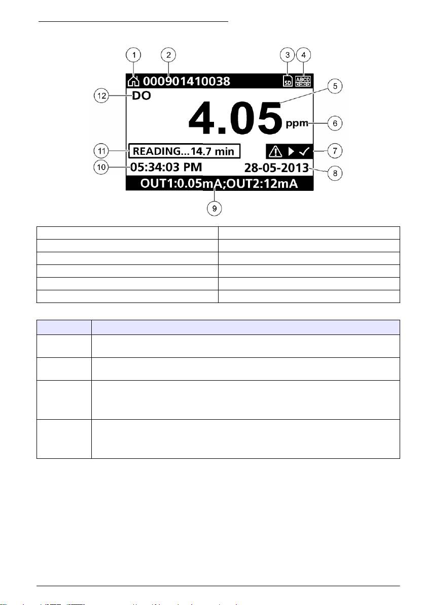
Figure 12 Example of Main Measurement screen
1 Home screen icon 7 Warning status bar
2 Sensor name 8 Date
3 SD Memory card icon 9 Analog output values
4 Relay status indicator 10 Time
5 Measurement value 11 Progress bar
6 Measurement unit 12 Measurement parameter
Table 5 Icon descriptions
Icon Description
Home screen The icon may vary depending on the screen or menu being displayed. For example, if an SD
card is installed, an SD card icon appears here when the user is in the SD Card Setup menu.
SD memory
This icon appears only if an SD card is in the reader slot. When a user is in the SD Card Setup
card
menu, this icon appears in the upper left corner.
Warning A warning icon consists of an exclamation point within a triangle. Warning icons appear on the
right of the main display below the measurement value. Push the enter key then select the
device to view any problems associated with that device. The warning icon will no longer be
displayed once all problems have been corrected or acknowledged.
Error An error icon consists of an exclamation point within a circle. When an error occurs, the error
icon and the measurement screen flash alternately in the main display. To view errors, push the
menu key and select DIAGNOSTICS. Then select the device to view any problems associated
with that device.
Additional display formats
• From the main measurement screen push the up and down arrow keys to switch between
measurement parameters
• From the main measurement screen push the right arrow key to switch to a split display of up to
4 measurement parameters. Push the right arrow key to include additional measurements. Push
the left arrow key as needed to return to the main measurement screen
• From the main measurement screen push the left arrow key to switch to the graphical display (see
Graphical display on page 22 to define the parameters). Push the up and down arrow keys to
switch measurement graphs
English
21
Оглавление
- English..............................................................................................................................3 Deutsch..........................................................................................................................27 Italiano............................................................................................................................53 Français.........................................................................................................................79 Español........................................................................................................................105 Português....................................................................................................................131 中文...............................................................................................................................157 Nederlands.................................................................................................................180 Polski............................................................................................................................206 Suomi............................................................................................................................232 Русский........................................................................................................................256
- Additional information
- Installation
- User interface and navigation
- System startup
- Maintenance
- Zusätzliche Informationen
- Installation
- Benutzerschnittstelle und Navigation
- Inbetriebnahme
- Wartung
- Fehlersuche
- Ulteriori informazioni
- Informazioni generali
- Installazione
- Interfaccia utente e navigazione
- Avvio del sistema
- Manutenzione
- Risoluzione dei problemi
- Informations supplémentaires
- Généralités
- Montage
- Interface utilisateur et navigation
- Démarrage du système
- Entretien
- Recherche de panne
- Información adicional
- Información general
- Instalación
- Interfaz del usuario y navegación
- Arranque del sistema
- Mantenimiento
- Solución de problemas
- Informação adicional
- Informação geral
- Instalação
- Interface do utilizador e navegação
- Arranque do sistema
- Manutenção
- Resolução de problemas
- 附加信息
- 安装
- 用户界面及导航
- 系统启动
- 维护
- Meer informatie
- Algemene informatie
- Installatie
- Gebruikersinterface en navigatie
- Het systeem starten
- Onderhoud
- Foutenopsporing
- Dodatkowe informacje
- Instalacja
- Interfejs użytkownika i nawigacja
- Uruchamianie systemu
- Konserwacja
- Rozwiązywanie problemów
- Lisätiedot
- Asennus
- Käyttöliittymä ja selaaminen
- Järjestelmän käynnistäminen
- Huolto
- Vianmääritys
- Дополнительная информация
- Общая информация
- Монтаж
- Пользовательский интерфейс и управление курсором
- Запуск системы
- Техническое обслуживание
