Hach-Lange POLYMETRON 9500 Basic User Manual: инструкция
Раздел: Техника
Тип:
Инструкция к Hach-Lange POLYMETRON 9500 Basic User Manual

DOC023.98.93058
Polymetron 9500 Controller
10/2013, Edition 3
Basic User Manual
Basishandbuch
Manuale dell'utente di base
Manuel d'utilisation de base
Manual básico del usuario
Manual de operações básicas
基本用户手册
Basisgebruikershandleiding
Podstawowa instrukcja obsługi
Peruskäyttöohje
Начальное руководство пользователя

English..............................................................................................................................3
Deutsch..........................................................................................................................27
Italiano............................................................................................................................53
Français.........................................................................................................................79
Español........................................................................................................................105
Português....................................................................................................................131
中文...............................................................................................................................157
Nederlands.................................................................................................................180
Polski............................................................................................................................206
Suomi............................................................................................................................232
Русский........................................................................................................................256
2
Additional information
Additional information is available on the manufacturer's website.
Specifications
Specifications are subject to change without notice.
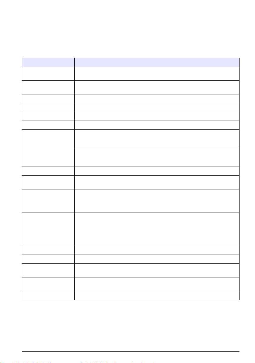
Specification Details
Component description Microprocessor-controlled and menu-driven controller that operates the sensor and
displays measured values.
Operating temperature -20 to 60 ºC (-4 to 140 ºF); 95% relative humidity, non-condensing with sensor load
<7 W; -20 to 50 ºC (-4 to 104 ºF) with sensor load <28 W
Storage temperature -20 to 70 ºC (-4 to 158 ºF); 95% relative humidity, non-condensing
Enclosure NEMA 4X/IP66 metal enclosure with a corrosion-resistant finish
European standards EN 61326-1: 2006; EN 61010-1:2010
ETL approved File 65454
Power requirements AC powered controller: 100-240 VAC ±10%, 50/60 Hz; Power 50 VA with 7 W
sensor/network module load, 100 VA with 28 W sensor/network module load
(optional Modbus RS232/RS485 or Profibus DPV1 network connection).
24 VDC powered controller: 24 VDC—15%, + 20%; Power 15 W with 7 W
sensor/network module load, 40 W with 28 W sensor/network module load (optional
Modbus RS232/RS485 or Profibus DPV1 network connection).
Altitude requirements Standard 2000 m (6562 ft) ASL (Above Sea Level)
Pollution degree /
Pollution Degree 2; Installation Category II
Installation category
Outputs Two analog (0-20 mA or 4-20 mA) outputs. Each analog output can be set to
0-20 mA or 4-20 mA, and can be assigned to represent a measured parameter such
as pH, temperature, flow or calculated values. Optional 3 additional analog outputs.
Secure Digital Memory card for use in data logging and software updates.
Relays Four SPDT, user-configured contacts, rated 5A 250 VAC (resistive). Contacts are
rated 250 VAC, 5 Amp resistive maximum for the AC powered controller and 24 VDC,
5A resistive maximum for the DC powered controller. Relays are designed for
connection to AC Mains circuits (i.e., whenever the controller is operated with 115 -
240 VAC power) or DC circuits (i.e., whenever the controller is operated with 24 VDC
power).
Dimensions ½ DIN—144 x 144 x 180.9 mm (5.7 x 5.7 x 7.12 in.)
Weight 1.7 kg (3.75 lb)
Digital communication Optional Modbus RS485/RS232 or Profibus DPV1 network connection for data
transmission
Data logging Secure Digital Card or special RS232 cable connector for data logging and
performing software updates
Warranty 2 years
General information
In no event will the manufacturer be liable for direct, indirect, special, incidental or consequential
damages resulting from any defect or omission in this manual. The manufacturer reserves the right to
make changes in this manual and the products it describes at any time, without notice or obligation.
Revised editions are found on the manufacturer’s website.
English
3
Safety information
N O T I C E
The manufacturer is not responsible for any damages due to misapplication or misuse of this product including,
without limitation, direct, incidental and consequential damages, and disclaims such damages to the full extent
permitted under applicable law. The user is solely responsible to identify critical application risks and install
appropriate mechanisms to protect processes during a possible equipment malfunction.
Please read this entire manual before unpacking, setting up or operating this equipment. Pay
attention to all danger and caution statements. Failure to do so could result in serious injury to the
operator or damage to the equipment.
Make sure that the protection provided by this equipment is not impaired. Do not use or install this
equipment in any manner other than that specified in this manual.
Use of hazard information
D A N G E R
Indicates a potentially or imminently hazardous situation which, if not avoided, will result in death or serious injury.
W A R N I N G
Indicates a potentially or imminently hazardous situation which, if not avoided, could result in death or serious
injury.
C A U T I O N
Indicates a potentially hazardous situation that may result in minor or moderate injury.
N O T I C E
Indicates a situation which, if not avoided, may cause damage to the instrument. Information that requires special
emphasis.
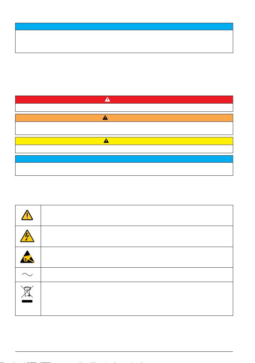
Precautionary labels
Read all labels and tags attached to the product. Personal injury or damage to the product could
occur if not observed. A symbol on the instrument is referenced in the manual with a precautionary
statement.
This symbol, when noted on a product, indicates a potential hazard which could cause serious
personal injury and/or death. The user should reference this instruction manual for operation and/or
safety information.
This symbol, when noted on a product enclosure or barrier, indicates that a risk of electrical shock
and/or electrocution exists and indicates that only individuals qualified to work with hazardous
voltages should open the enclosure or remove the barrier.
This symbol, when noted on the product, indicates the presence of devices sensitive to electrostatic
discharge and indicates that care must be taken to prevent damage to them.
This symbol, when noted on a product, indicates the instrument is connected to alternate current.
Electrical equipment marked with this symbol may not be disposed of in European public disposal
systems. In conformity with European local and national regulations, European electrical equipment
users must now return old or end-of-life equipment to the manufacturer for disposal at no charge to
the user.
Note: For return for recycling, please contact the equipment producer or supplier for instructions on how to return
end-of-life equipment, producer-supplied electrical accessories, and all auxiliary items for proper disposal.
4 English
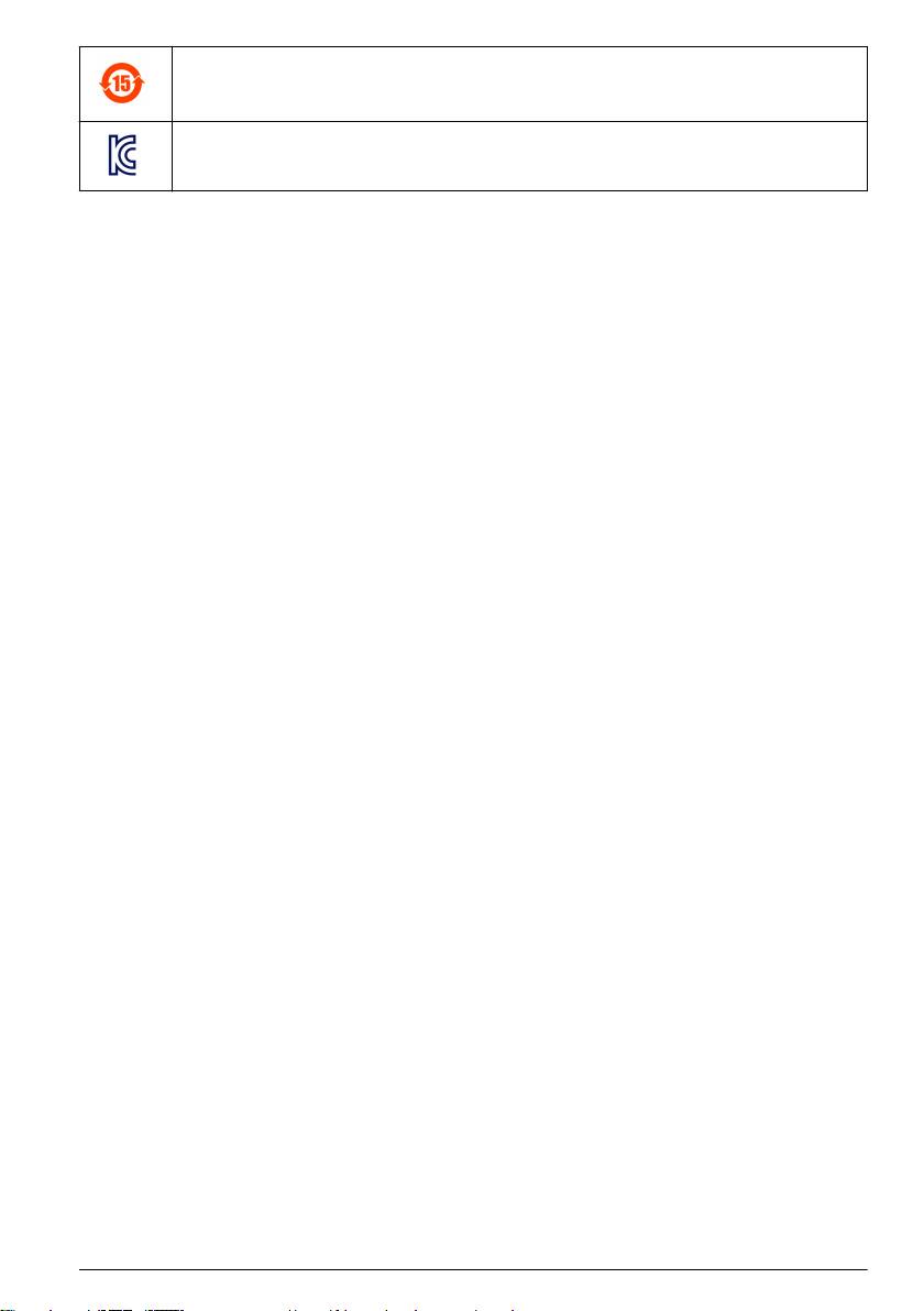
Products marked with this symbol indicates that the product contains toxic or hazardous substances
or elements. The number inside the symbol indicates the environmental protection use period in
years.
Products marked with this symbol indicates that the product conforms to relevant South Korean
EMC standards.
Certification
Canadian Radio Interference-Causing Equipment Regulation, IECS-003, Class A:
Supporting test records reside with the manufacturer.
This Class A digital apparatus meets all requirements of the Canadian Interference-Causing
Equipment Regulations.
FCC Part 15, Class "A" Limits
Supporting test records reside with the manufacturer. The device complies with Part 15 of the FCC
Rules. Operation is subject to the following conditions:
1. The equipment may not cause harmful interference.
2. The equipment must accept any interference received, including interference that may cause
undesired operation.
Changes or modifications to this equipment not expressly approved by the party responsible for
compliance could void the user's authority to operate the equipment. This equipment has been tested
and found to comply with the limits for a Class A digital device, pursuant to Part 15 of the FCC rules.
These limits are designed to provide reasonable protection against harmful interference when the
equipment is operated in a commercial environment. This equipment generates, uses and can
radiate radio frequency energy and, if not installed and used in accordance with the instruction
manual, may cause harmful interference to radio communications. Operation of this equipment in a
residential area is likely to cause harmful interference, in which case the user will be required to
correct the interference at their expense. The following techniques can be used to reduce
interference problems:
1. Disconnect the equipment from its power source to verify that it is or is not the source of the
interference.
2. If the equipment is connected to the same outlet as the device experiencing interference, connect
the equipment to a different outlet.
3. Move the equipment away from the device receiving the interference.
4. Reposition the receiving antenna for the device receiving the interference.
5. Try combinations of the above.
Product overview
The controller displays sensor measurements and other data, can transmit analog and digital signals,
and can interact with and control other devices through outputs and relays. Outputs, relays, sensors
and sensor modules are configured and calibrated through the user interface on the front of the
controller.
Figure 1 shows the product components. Components may vary according to controller configuration.
Contact the manufacturer if parts are damaged or missing.
English
5
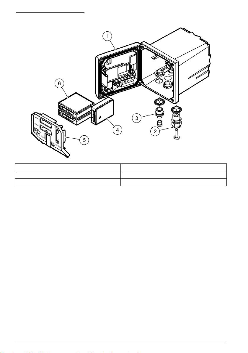
Figure 1 System components
1 Controller 4 Network module (optional)
2 Cable gland assembly 5 High-voltage barrier
3 Additional connection fitting 6 Sensor modules (optional)
Sensors and sensor modules
The controller accepts up to a maximum of two sensor modules along with one communication
module. A variety of sensors can be wired to the sensor modules. Sensor wiring information is given
in the specific sensor manuals and in the user instructions for specific modules.
Relays, outputs and signals
The controller has four configurable relay switches and two analog outputs. An optional analog
output module can increase the number of analog outputs to five.
Device scans
With two exceptions, the controller automatically scans for connected devices without user input
when it is powered on. The first exception is when the controller is powered on for the first time
before initial use. The second exception is after the controller configuration settings have been set to
their default values and the controller is powered on. In both cases, the controller first displays the
language, date and time edit screens. After the language, date and time entries are accepted, the
controller performs a device scan.
Controller enclosure
The controller enclosure is NEMA 4X/IP66-rated and has a corrosion-resistant finish designed to
withstand corrosive environmental constituents such as salt spray and hydrogen sulfide. Protection
against environmental damage is strongly recommended for outdoor use.
Note: Units that have the Underwriters Laboratories (UL) certification are intended for indoor use only and do not
have a NEMA 4X/IP66 rating.
Controller mounting options
The controller can be mounted to a panel, to a wall or to a vertical or horizontal pipe. A neoprene
sealing gasket is included and can be used to reduce vibration. The gasket can be used as a
template for panel mounting before the inner gasket component is separated.
6
English
Оглавление
- English..............................................................................................................................3 Deutsch..........................................................................................................................27 Italiano............................................................................................................................53 Français.........................................................................................................................79 Español........................................................................................................................105 Português....................................................................................................................131 中文...............................................................................................................................157 Nederlands.................................................................................................................180 Polski............................................................................................................................206 Suomi............................................................................................................................232 Русский........................................................................................................................256
- Additional information
- Installation
- User interface and navigation
- System startup
- Maintenance
- Zusätzliche Informationen
- Installation
- Benutzerschnittstelle und Navigation
- Inbetriebnahme
- Wartung
- Fehlersuche
- Ulteriori informazioni
- Informazioni generali
- Installazione
- Interfaccia utente e navigazione
- Avvio del sistema
- Manutenzione
- Risoluzione dei problemi
- Informations supplémentaires
- Généralités
- Montage
- Interface utilisateur et navigation
- Démarrage du système
- Entretien
- Recherche de panne
- Información adicional
- Información general
- Instalación
- Interfaz del usuario y navegación
- Arranque del sistema
- Mantenimiento
- Solución de problemas
- Informação adicional
- Informação geral
- Instalação
- Interface do utilizador e navegação
- Arranque do sistema
- Manutenção
- Resolução de problemas
- 附加信息
- 安装
- 用户界面及导航
- 系统启动
- 维护
- Meer informatie
- Algemene informatie
- Installatie
- Gebruikersinterface en navigatie
- Het systeem starten
- Onderhoud
- Foutenopsporing
- Dodatkowe informacje
- Instalacja
- Interfejs użytkownika i nawigacja
- Uruchamianie systemu
- Konserwacja
- Rozwiązywanie problemów
- Lisätiedot
- Asennus
- Käyttöliittymä ja selaaminen
- Järjestelmän käynnistäminen
- Huolto
- Vianmääritys
- Дополнительная информация
- Общая информация
- Монтаж
- Пользовательский интерфейс и управление курсором
- Запуск системы
- Техническое обслуживание
