Hach-Lange POLYMETRON 9500 Basic User Manual: Installation
Installation: Hach-Lange POLYMETRON 9500 Basic User Manual
Installation
Mounting components and dimensions
C A U T I O N
Personal injury hazard. Only qualified personnel should conduct the tasks described in this section of the manual.
The controller can be installed on a surface, panel or pipe (horizontal or vertical). For mounting
options and instructions, refer to Figure 2, Figure 3 on page 8, Figure 4 on page 9, Figure 5
on page 10 and Figure 6 on page 11.
For horizontal pipe mounts, the mounting feet (Figure 2) must be attached to the mounting bracket in
a vertical position.
For both horizontal and vertical pipe mounts, attach the mounting bracket to the controller as shown
in Figure 5 on page 10.
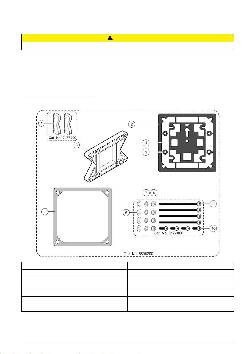
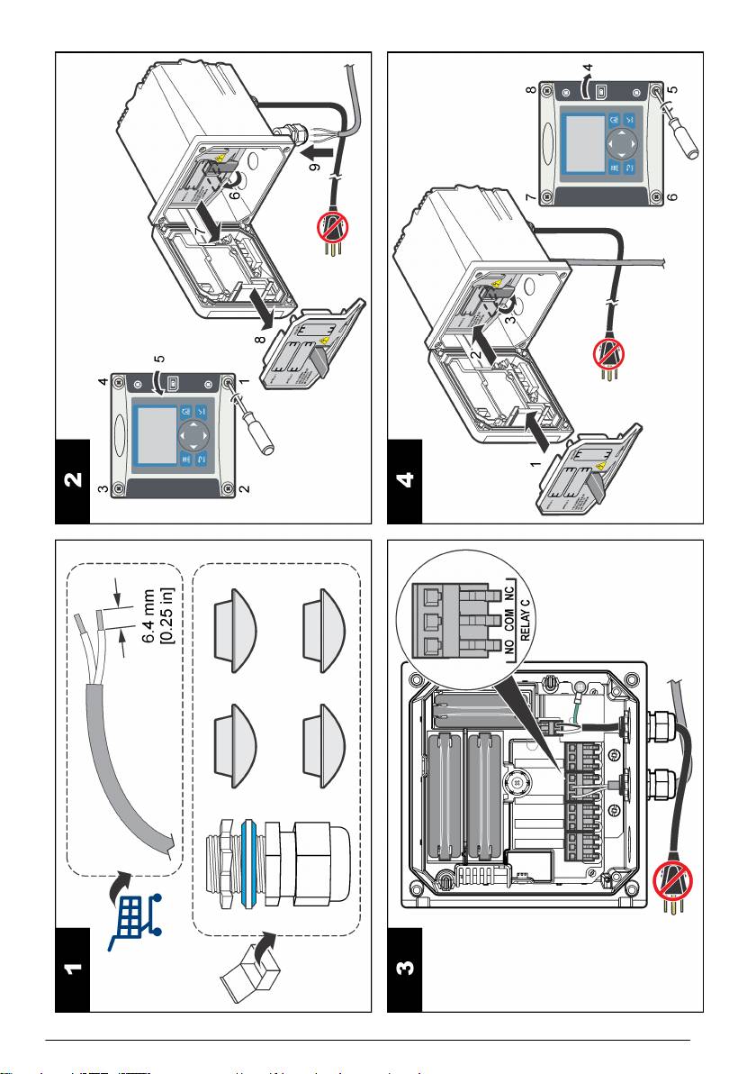
Figure 2 Mounting components
1 Mounting foot (2x) 7 Lock washer, ¼-inch ID (4x)
2 Sealing gasket for panel mount, Neoprene 8 M5 x 0.8 Keps hexnut (4x)
3 Bracket for wall and pipe mounting 9 Pan head screws, M5 x 0.8 x 100mm (4x) (Used for
variable diameter pipe mount installations)
4 Vibration isolation gasket for pipe mount 10 Pan head screws, M5 x 0.8 x 15 mm (4x)
5 Vibration isolation washer for pipe mount (4x) 11 Bracket for panel mounting
6 Flat washer, ¼-inch ID (4x)
English 7
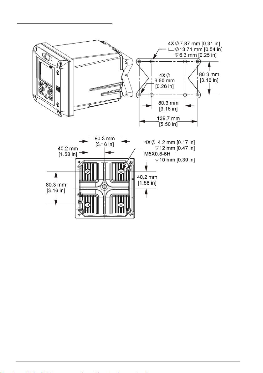
Controller mounting
Figure 3 Surface mounting dimensions
8 English
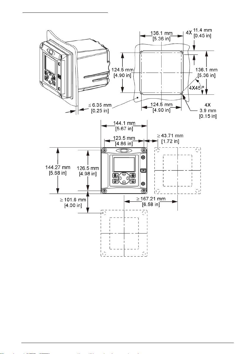
Figure 4 Panel mounting dimensions
Note: If using the bracket for panel mounting (supplied), push the controller through the hole in the panel and then
slide the bracket over the controller on the back side of the panel. Use the four 15 mm pan head screws (supplied)
to attach the bracket to the controller and secure the controller to the panel.
English
9
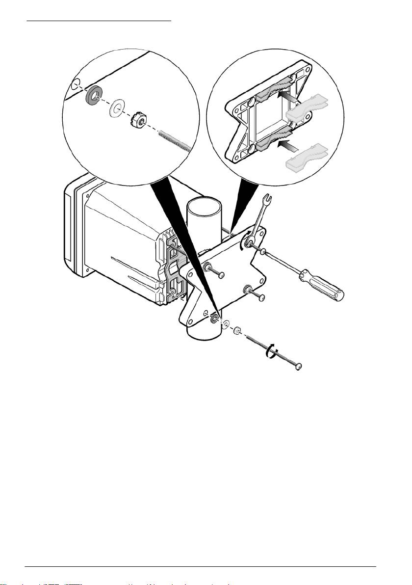
Figure 5 Pipe mounting (vertical pipe)
10 English
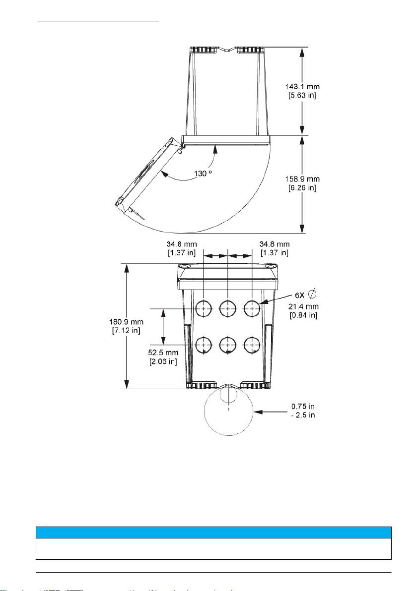
Figure 6 Top and bottom views
High-voltage barrier
High-voltage wiring for the controller is located behind the high-voltage barrier in the controller
enclosure. The barrier must remain in place except when installing modules or when a qualified
installation technician is wiring for power, alarms, outputs or relays. Do not remove the barrier while
power is applied to the controller.
Electrostatic discharge (ESD) considerations
N O T I C E
Potential Instrument Damage. Delicate internal electronic components can be damaged by static electricity,
resulting in degraded performance or eventual failure.
English 11
Refer to the steps in this procedure to prevent ESD damage to the instrument:
• Touch an earth-grounded metal surface such as the chassis of an instrument, a metal conduit or
pipe to discharge static electricity from the body.
• Avoid excessive movement. Transport static-sensitive components in anti-static containers or
packages.
• Wear a wrist strap connected by a wire to earth ground.
• Work in a static-safe area with anti-static floor pads and work bench pads.
Wiring overview
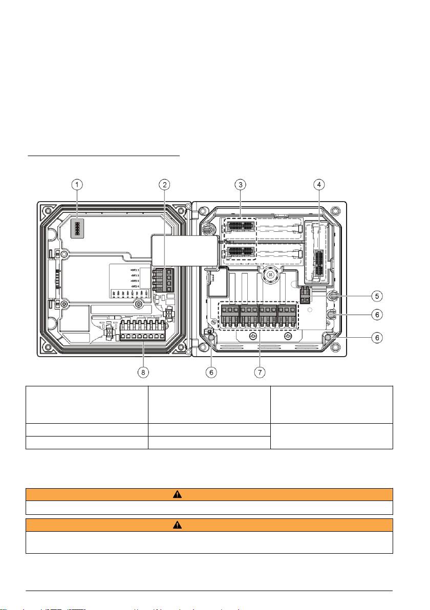
Figure 7 shows an overview of the wiring connections inside the controller with the high voltage
barrier removed. The left side of the figure shows the back side of the controller cover.
Note: Remove connector caps from the connectors before module installation.
Figure 7 Wiring connections overview
1
1 Service cable connection 4 Communication module
7 Relay connections
connector (e.g., Modbus,
Profibus, optional 4-20 mA
module, etc.)
1
1
1
2 4-20 mA output
5 AC and DC power connector
8 Discrete input wiring connector
3 Sensor module connector 6 Ground terminals
1
Terminals can be removed for improved access.
Wiring for power
W A R N I N G
Potential Electrocution Hazard. Always disconnect power to the instrument when making electrical connections.
W A R N I N G
Potential Electrocution Hazard. If this equipment is used outdoors or in potentially wet locations, a Ground Fault
Interrupt device must be used for connecting the equipment to its mains power source.
12 English
D A N G E R
Electrocution Hazard. Do not connect AC power to a 24 VDC powered model.
W A R N I N G
Potential Electrocution Hazard. A protective earth (PE) ground connection is required for both 100-240 VAC and
24 VDC wiring applications. Failure to connect a good PE ground connection can result in shock hazards and
poor performance due to electromagnetic interferences. ALWAYS connect a good PE ground to the controller
terminal.
N O T I C E
Install the device in a location and position that gives easy access to the disconnect device and its operation.
The controller can be purchased as either a 100-240 VAC powered model or a 24 VDC powered
model. Follow the appropriate wiring instructions for the purchased model.
The controller can be wired for line power by hard-wiring in conduit or wiring to a power cord.
Regardless of the wire used, the connections are made at the same terminals. A local disconnect
designed to meet local electrical code is required and must be identified for all types of installation. In
hard-wired applications, the power and safety ground service drops for the instrument must be 18 to
12 AWG.
Notes:
• The voltage barrier must be removed before making any electrical connections. After making all
connections, replace the voltage barrier before closing the controller cover.
• A sealing type cable gland and a power cord less than 3 meters (10 feet) in length with three 18-
gauge conductors (including a safety ground wire) can be used to maintain the NEMA
4X/IP66 environmental rating.
• Controllers can be ordered with AC power cords pre-installed. Additional power cords may also be
ordered.
• The DC power source that supplies power to the 24 VDC powered controller must maintain
voltage regulation within the specified 24 VDC-15% +20% voltage limits. The DC power source
must also provide adequate protection against surges and line transients.
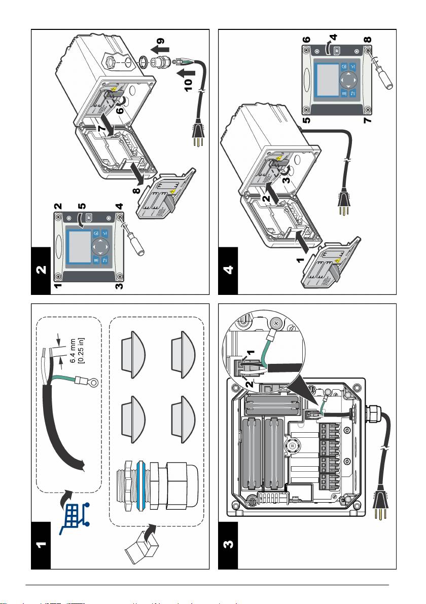
Wiring procedure
Follow the numbered steps and Table 1 or Table 2 to wire the controller for power. Insert each wire
into the appropriate terminal until the insulation is seated against the connector with no bare wire
exposed. Tug gently after insertion to make a secure connection. Seal any unused openings in the
controller box with conduit opening sealing plugs.
Table 1 AC power wiring information (AC powered models only)
Terminal Description Color—N. America Color—EU
1 Hot (L1) Black Brown
2 Neutral (L2) White Blue
— Protective earth (PE) Ground lug Green Green and yellow
Table 2 DC power wiring information (DC powered models only)
Terminal Description Color—N. America Color—EU
1 +24 VDC Red Red
2 24 VDC return Black Black
— Protective earth (PE) Ground lug Green Green and yellow
English 13
14 English
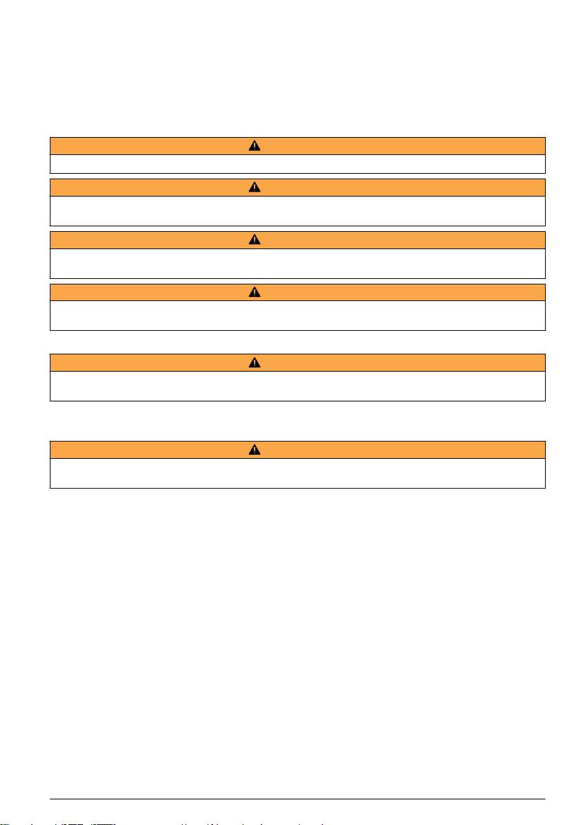
Alarms and relays
The controller is equipped with four unpowered, single pole relays rated 100-250 VAC, 50/60 Hz,
5 amp resistive maximum. Contacts are rated 250 VAC, 5 amp resistive maximum for the AC
powered controller and 24 VDC, 5A resistive maximum for the DC powered controller. The relays are
not rated for inductive loads.
Wiring relays
W A R N I N G
Potential Electrocution Hazard. Always disconnect power to the instrument when making electrical connections.
W A R N I N G
Potential fire hazard. The relay contacts are rated 5A and are not fused. External loads connected to the relays
must have current limiting devices provided to limit current to < 5 A.
W A R N I N G
Potential fire hazard. Do not daisy-chain the common relay connections or jumper wire from the mains power
connection inside the instrument.
W A R N I N G
Potential electrocution hazard. In order to maintain the NEMA/IP environmental ratings of the enclosure, use only
conduit fittings and cable glands rated for at least NEMA 4X/IP66 to route cables in to the instrument.
AC line (100—250 V) powered controllers
W A R N I N G
Potential electrocution hazard. AC mains powered controllers (115 V–230 V) are designed for relay connections
to AC mains circuits (i.e. voltages greater than 16 V-RMS, 22.6 V-PEAK or 35 VDC).
The wiring compartment is not designed for voltage connections in excess of 250 VAC.
24 VDC powered controllers
W A R N I N G
Potential electrocution hazard. 24 V powered controllers are designed for relay connections to low voltage circuits
(i.e. voltages less than 16 V-RMS, 22.6 V-PEAK or 35 VDC).
The 24 VDC controller relays are designed for connection to LOW voltage circuits (i.e., voltages less
than 30 V-RMS, 42.2 V-PEAK or 60 VDC). The wiring compartment is not designed for voltage
connections above these levels.
The relay connector accepts 18-12 AWG wire (as determined by load application). Wire gauge less
than 18 AWG is not recommended.
The Normally Open (NO) and Common (COM) relay contacts will be connected when an alarm or
other condition is active. The Normally Closed (NC) and Common relay contacts will be connected
when an alarm or other condition is inactive (unless the Fail Safe is set to Yes) or when power is
removed from the controller.
Most relay connections use either the NO and COM terminals or the NC and COM terminals. The
numbered installation steps show connection to the NO and COM terminals.
English
15
16 English
Analog output connections
W A R N I N G
Potential Electrocution Hazard. Always disconnect power to the instrument when making electrical connections.
W A R N I N G
Potential electrocution hazard. In order to maintain the NEMA/IP environmental ratings of the enclosure, use only
conduit fittings and cable glands rated for at least NEMA 4X/IP66 to route cables in to the instrument.
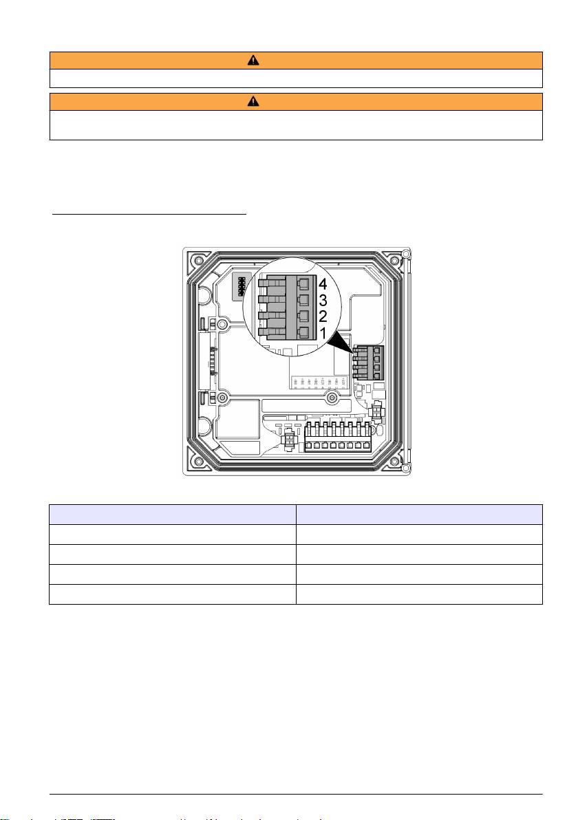
Two isolated analog outputs are provided. Such outputs are commonly used for analog signaling or
to control other external devices. Make wiring connections to the controller as shown in Figure 8 and
Table 3.
Note: Figure 8 shows the back of the controller cover and not the inside of the main controller compartment.
Figure 8 Analog output connections
Table 3 Output connections
Recorder wires Circuit board position
Output 2- 4
Output 2+ 3
Output 1- 2
Output 1+ 1
1. Open the controller cover.
2. Feed the wires through the cable gland.
3. Adjust the wire as necessary and tighten the cable gland.
4. Make connections with twisted-pair shielded wire and connect the shield at the controlled
component end or at the control loop end.
• Do not connect the shield at both ends of the cable.
• Use of non-shielded cable may result in radio frequency emission or susceptibility levels higher
than allowed.
• Maximum loop resistance is 500 ohm.
5. Close the controller cover and tighten the cover screws.
6. Configure outputs in the controller.
English
17
Discrete input wiring connections
W A R N I N G
Potential Electrocution Hazard. Always disconnect power to the instrument when making electrical connections.
W A R N I N G
Potential electrocution hazard. In order to maintain the NEMA/IP environmental ratings of the enclosure, use only
conduit fittings and cable glands rated for at least NEMA 4X/IP66 to route cables in to the instrument.
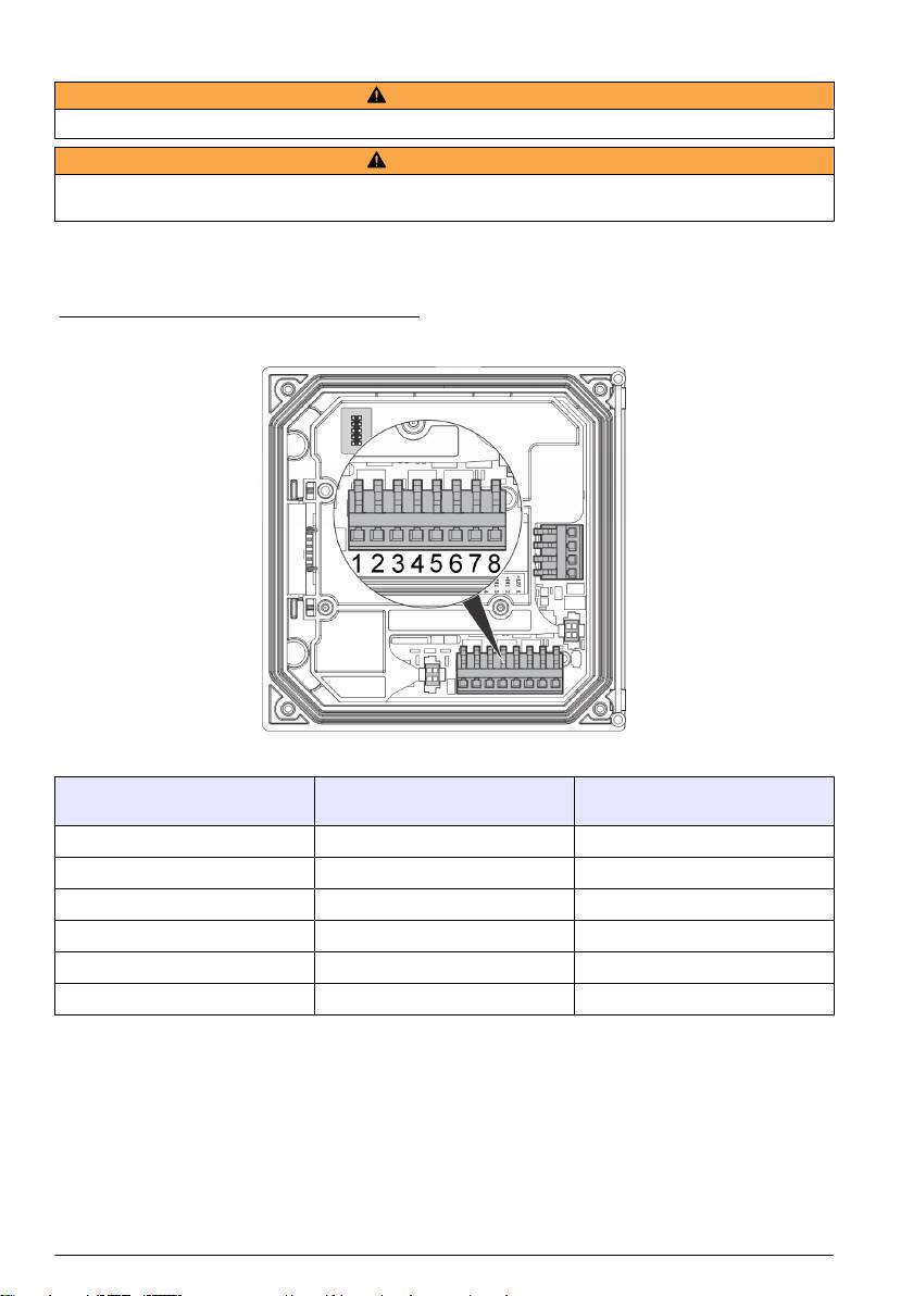
Three discrete inputs are provided for switch closure inputs or logic level voltage inputs. Make wiring
connections and configure jumper settings to the controller as shown in Figure 9, Table 4 and
Figure 10.
Note: Figure 9 shows the back of the controller cover and not the inside of the main controller compartment.
Figure 9 Discrete input wiring connections
Table 4 Input connections
Discrete inputs Connector position - Switch input Connector position - Voltage
input
Input 1+ 3 2
Input 1- 2 3
Input 2+ 6 5
Input 2- 5 6
Input 3+ 8 7
Input 3- 7 8
18 English
Оглавление
- English..............................................................................................................................3 Deutsch..........................................................................................................................27 Italiano............................................................................................................................53 Français.........................................................................................................................79 Español........................................................................................................................105 Português....................................................................................................................131 中文...............................................................................................................................157 Nederlands.................................................................................................................180 Polski............................................................................................................................206 Suomi............................................................................................................................232 Русский........................................................................................................................256
- Additional information
- Installation
- User interface and navigation
- System startup
- Maintenance
- Zusätzliche Informationen
- Installation
- Benutzerschnittstelle und Navigation
- Inbetriebnahme
- Wartung
- Fehlersuche
- Ulteriori informazioni
- Informazioni generali
- Installazione
- Interfaccia utente e navigazione
- Avvio del sistema
- Manutenzione
- Risoluzione dei problemi
- Informations supplémentaires
- Généralités
- Montage
- Interface utilisateur et navigation
- Démarrage du système
- Entretien
- Recherche de panne
- Información adicional
- Información general
- Instalación
- Interfaz del usuario y navegación
- Arranque del sistema
- Mantenimiento
- Solución de problemas
- Informação adicional
- Informação geral
- Instalação
- Interface do utilizador e navegação
- Arranque do sistema
- Manutenção
- Resolução de problemas
- 附加信息
- 安装
- 用户界面及导航
- 系统启动
- 维护
- Meer informatie
- Algemene informatie
- Installatie
- Gebruikersinterface en navigatie
- Het systeem starten
- Onderhoud
- Foutenopsporing
- Dodatkowe informacje
- Instalacja
- Interfejs użytkownika i nawigacja
- Uruchamianie systemu
- Konserwacja
- Rozwiązywanie problemów
- Lisätiedot
- Asennus
- Käyttöliittymä ja selaaminen
- Järjestelmän käynnistäminen
- Huolto
- Vianmääritys
- Дополнительная информация
- Общая информация
- Монтаж
- Пользовательский интерфейс и управление курсором
- Запуск системы
- Техническое обслуживание
