Hach-Lange SC 200 Active 4-20 mA Output Module User Manual: инструкция
Раздел: Техника
Тип:
Инструкция к Hach-Lange SC 200 Active 4-20 mA Output Module User Manual
DOC023.98.80192
sc200 Active 4-20 mA Output Module
03/2011, Edition 1
User Manual
Bedienungsanleitung
Manuale dell'utente
Manuel d'utilisation
Manual del usuario
Manual do utilizador
Uživatelská příručka
Brugsanvisning
Gebruikershandleiding
Instrukcja obsługi
Bruksanvisning
Käyttäjän käsikirja
Ръководство на потребителя
Használati útmutató
Manual de utilizare
Naudotojo vadovas
Руководство пользователя
Kullanım Kılavuzu
Návod na obsluhu
Navodila za uporabo
Korisnički priručnik
Εγχειρίδιο λειτουργίας
Kasutusjuhend

English..................................................................................................................................................................................................3
Deutsch................................................................................................................................................................................................9
Italiano................................................................................................................................................................................................15
Français.............................................................................................................................................................................................22
Español..............................................................................................................................................................................................28
Português..........................................................................................................................................................................................35
Čeština...............................................................................................................................................................................................41
Dansk..................................................................................................................................................................................................48
Nederlands.......................................................................................................................................................................................54
Polski...................................................................................................................................................................................................60
Svenska.............................................................................................................................................................................................66
Suomi..................................................................................................................................................................................................72
български.........................................................................................................................................................................................78
Magyar................................................................................................................................................................................................
85
Română.............................................................................................................................................................................................91
lietuvių kalba....................................................................................................................................................................................97
Русский............................................................................................................................................................................................103
Türkçe...............................................................................................................................................................................................109
Slovenský jazyk...........................................................................................................................................................................115
Slovenski.........................................................................................................................................................................................121
Hrvatski............................................................................................................................................................................................127
Ελληνικά..........................................................................................................................................................................................133
eesti keel.........................................................................................................................................................................................140
2
General Information
This symbol, if noted on the instrument, references the instruction
manual for operation and/or safety information.
In no event will the manufacturer be liable for direct, indirect, special,
incidental
or consequential damages resulting from any defect or omission
in this manual. The manufacturer reserves the right to make changes in
This symbol, when noted on a product enclosure or barrier, indicates
this manual and the products it describes at any time, without notice or
that a risk of electrical shock and/or electrocution exists.
obligation. Revised editions are found on the manufacturer’s website.
Safety information
Delicate internal electronic components can be damaged by static
electricity, resulting in degraded performance or eventual failure.
Please read this entire manual before unpacking, setting up or operating
this equipment. Pay attention to all danger and caution statements. Failure
to do so could result in serious injury to the operator or damage to the
equipment.
Electrical equipment marked with this symbol may not be disposed of
in European public disposal systems after 12 August of 2005. In
Make sure that the protection provided by this equipment is not impaired,
conformity with European local and national regulations (EU Directive
do not use or install this equipment in any manner other than that specified
2002/98/EC),
European electrical equipment users must now return old
in this manual.
or end-of-life equipment to the Producer for disposal at no charge to
the user.
Use of hazard information
Note: For return for recycling, please contact the equipment producer or supplier
for instructions on how to return end-of-life equipment, producer-supplied electrical
D A N G E R
accessories, and all auxillary items for proper disposal.
Indicates a potentially or imminently hazardous situation which, if not avoided, will
result in death or serious injury.
Overview of the 4-20 mA output module
W A R N I N G
The 4-20 mA output module gives three additional 4-20 mA output
connections to a controller. The module connects to the network card
Indicates a potentially or imminently hazardous situation which, if not avoided,
connector inside the controller.
could result in death or serious injury.
C A U T I O N
Installation
Indicates a potentially hazardous situation that may result in minor or moderate
W A R N I N G
injury.
Potential Electrocution Hazard. Always disconnect power to the
N O T I C E
instrument when making electrical connections.
Indicates a situation which, if not avoided, may cause damage to the instrument.
Information that requires special emphasis.
W A R N I N G
Precautionary labels
Potential Electrocution Hazard. Only qualified personnel should conduct
Read all labels and tags attached to the instrument. Personal injury or
the tasks described in this section of the manual.
damage to the instrument could occur if not observed. A symbol on the
instrument is referenced in the manual with a precautionary statement.
English 3
N O T I C E
Table 2 Wiring information for external customer powered
(continued)
Potential Instrument Damage. Delicate internal electronic components
can
be damaged by static electricity, resulting in degraded performance
Output Connection Connector pin number
or eventual failure.
Output B (+) IN 5
Three isolated analog outputs (output 1–output 3) are provided. Such
— — 6
outputs
are commonly used for analog signaling or to control other external
devices. Each output is loop powered and requires a customer supplied
Output A (–) IN 7
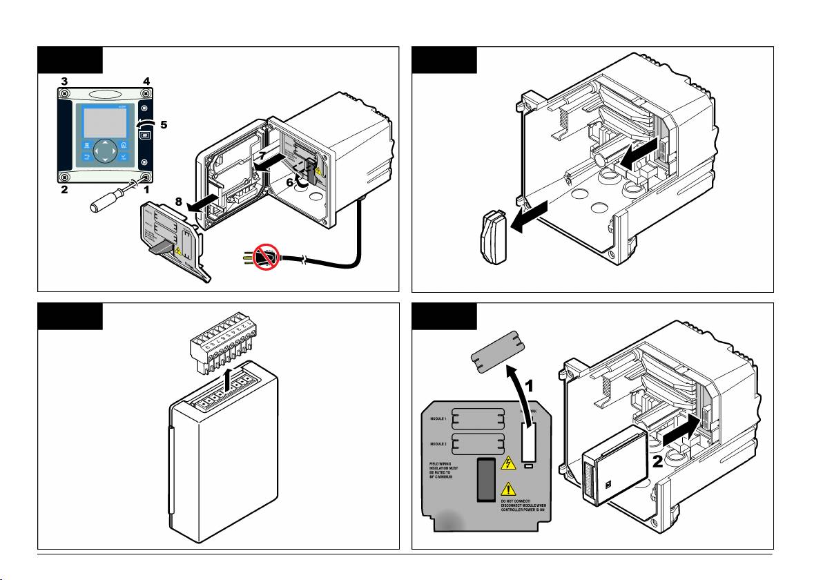
12 to 24 VDC power supply or the use of internal module power. To install
the module and connect the outputs, refer to the Illustrated steps
Output A (+) IN 8
on page 6 and either Table 1 or Table 2.
— — 9
Table 1 Wiring information for module powered
1. Disconnect controller power.
Output Connection Connector pin number
2. Open the controller cover.
Output C (+) IN 1
3. Feed the twisted-pair shielded wire through the strain relief.
— — 2
4. Adjust the wire as necessary and tighten the strain relief.
Output C (–) IN 3
5. Connect
the shield at the power supply side. The power supply positive
polarity connects to the (+) terminal, and the negative polarity connects
Output B (+) IN 4
to the (-) terminal (Figure 1 or Figure 2).
— — 5
• Do not connect the shield at both ends of the cable.
Output B (–) IN 6
• Use only shielded cable to minimize radio frequency emissions and
susceptibility.
Output A (+) IN 7
• External loop resistance may be required (Table 3 or Table 4).
— — 8
6. Close the controller cover and tighten the cover screws.
Output A (–) IN 9
7. Connect controller power.
8. Configure outputs in the controller.
Table 2 Wiring information for external customer powered
Output Connection Connector pin number
Output C (–) IN 1
Output C (+) IN 2
— — 3
Output B (–) IN 4
4 English
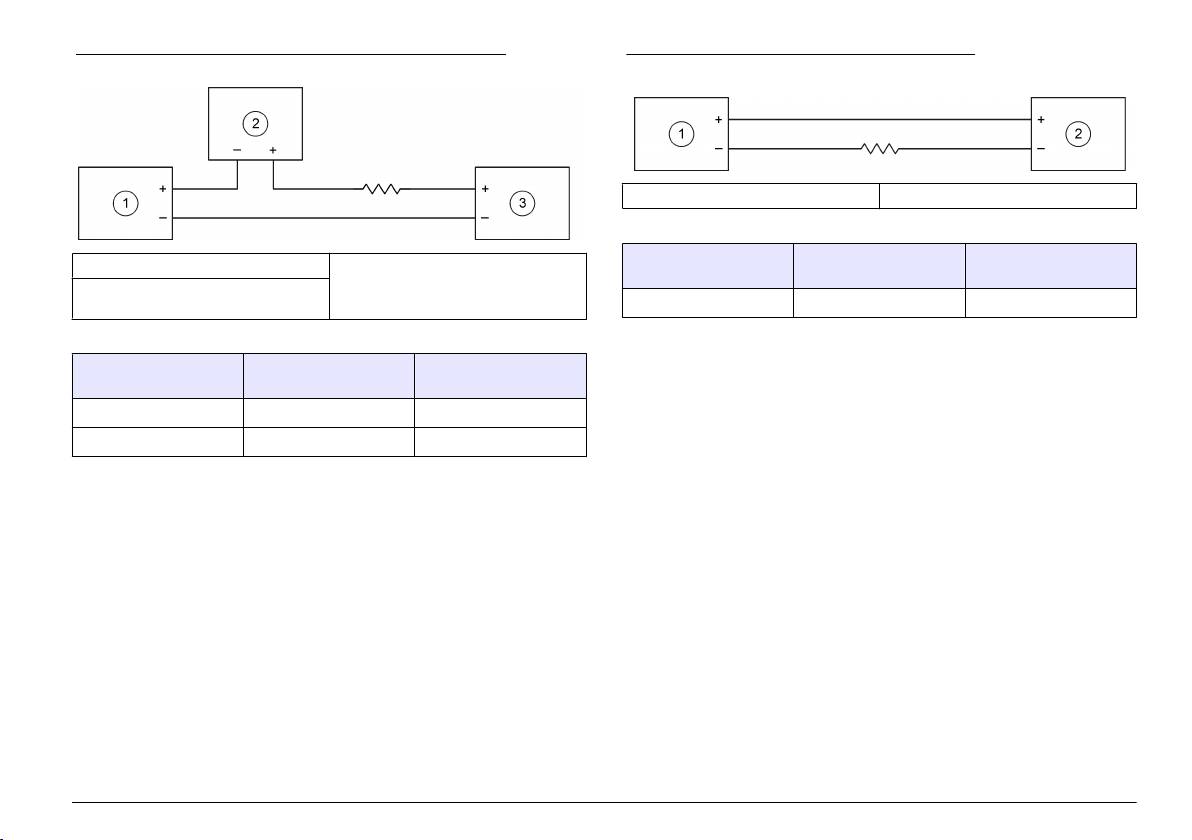
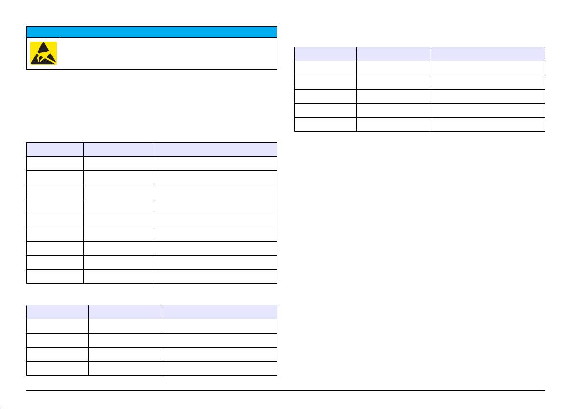
Figure 1 Wiring diagram for external customer powered
Figure 2 Wiring diagram for module powered
1 4–20 mA output module 2 External device (HART master)
Table 4 Resistance values for module powered
Power supply voltage Loop minimal
Loop maximal
1 4–20 mA output module 3 Customer power supply
resistance
resistance
2 External device (Recorder/data
acquisition system)
15 VDC 0 Ω 350 Ω typical
Table 3 Resistance values for external customer powered
Power supply voltage Loop minimal
Loop maximal
resistance
resistance
12–18 VDC 0 Ω 250 Ω typical
18–24 VDC 250 Ω 500 Ω typical
English 5
1 2
3 4
6 English
