Hach-Lange SENSION+ MM374: инструкция
Раздел: Техника
Тип:
Инструкция к Hach-Lange SENSION+ MM374

DOC022.98.90253
™
sensION
+ MM374
12/2013, Edition 4
User Manual
Bedienungsanleitung
Manuale dell'utente
Manuel d'utilisation
Manual del usuario
Manual do utilizador
Uživatelská příručka
Brugsanvisning
Gebruikershandleiding
Instrukcja obsługi
Bruksanvisning
Käyttäjän käsikirja
Ръководство на потребителя
Használati útmutató
Manual de utilizare
Naudotojo vadovas
Руководство пользователя
Kullanım Kılavuzu
Návod na obsluhu
Navodila za uporabo
Korisnički priručnik
Εγχειρίδιο χρήσης
Kasutusjuhend

English...................................................................................................................................................................................................3
Deutsch...............................................................................................................................................................................................23
Italiano.................................................................................................................................................................................................44
Français..............................................................................................................................................................................................65
Español...............................................................................................................................................................................................86
Português........................................................................................................................................................................................107
Čeština..............................................................................................................................................................................................128
Dansk.................................................................................................................................................................................................149
Nederlands......................................................................................................................................................................................169
Polski.................................................................................................................................................................................................190
Svenska............................................................................................................................................................................................211
Suomi.................................................................................................................................................................................................231
български.......................................................................................................................................................................................252
Magyar..............................................................................................................................................................................................274
Română............................................................................................................................................................................................295
lietuvių kalba...................................................................................................................................................................................316
Русский............................................................................................................................................................................................337
Türkçe................................................................................................................................................................................................360
Slovenský jazyk............................................................................................................................................................................381
Slovenski..........................................................................................................................................................................................402
Hrvatski.............................................................................................................................................................................................423
Ελληνικά...........................................................................................................................................................................................444
eesti keel..........................................................................................................................................................................................467
2
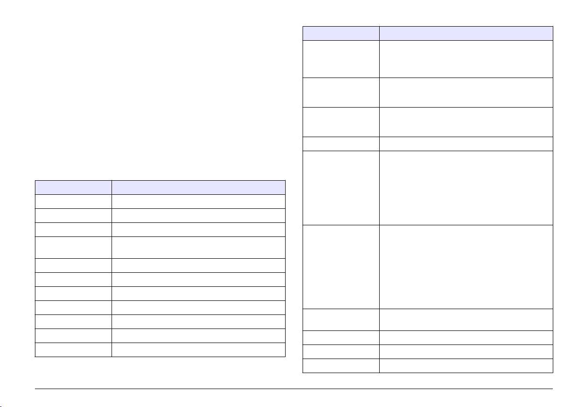
Table of contents
Specification Details
Specifications on page 3 Advanced operation on page 12
Resolution pH: 0.1/0.01/0.001, ORP: 0.1/1 mV, ISE:
programmable, temperature: 0.1 ºC (0.18 ºF), EC:
General information on page 4 Data logger on page 13
variable, resistivity: variable, NaCl: variable, TDS:
variable
Installation on page 5 Maintenance on page 15
Measuring error (±
pH: ≤ 0.005, ORP: ≤ 0.2 mV, temperature: ≤ 0.2 ºC (≤
User interface and navigation
Troubleshooting on page 17
1 digit)
0.36 ºF), EC: ≤ 0.5%, resistivity: ≤ 0.5 %, NaCl: ≤
on page 8
0.5 %, TDS: ≤ 0.5%
Startup on page 9 Replacement parts and accessories
Reproducibility (±
pH: ± 0.001, ORP: ± 0.1 mV, temperature: ± 0.1 ºC (±
on page 18
1 digit)
0.18 ºF), EC: ± 0.1%, resistivity: ± 0.1%, NaCl ± 0.1%,
TDS ± 0.1%
Standard operation on page 9 Standard solutions on page 19
Data storage 330 results and last 9 calibrations
Specifications
Connections 2 Combined or indicator probe: BNC connector (Imp.
>10
12
Ω); 2 Reference electrodes: banana connector;
Specifications are subject to change without notice.
A.T.C. type Pt 1000: banana or telephonic; 2 magnetic
stirrers: RCA connector
Specification Details
Conductivity probe with built-in Pt1000 sensor (or NTC
Dimensions 35 x 20 x 11 cm (13.78 x 7.87 x 4.33 in.)
10 kΩ probe): telephonic connector
RS232C for printer or PC: telephonic connector;
Weight 1100 g (2.43 lb)
external PC keyboard: mini DIN connector
Meter enclosure IP42
Temperature correction Channel 1 pH: Pt 1000 temperature probe (A.T.C.),
NTC 10 kΩ probe, manual, Channel 2 temperature,
Power requirements
100–240 V, 0.4 A, 47-63 Hz
isopotential pH programmable, standard value 7.00,
(external)
CE: Pt 1000 temperature probe (A.T.C.), linear
Meter protection class Class II
function, TC=0.00 to 9.99%/Temperature, TRef: 20°C
(68 °F) or 25°C (77 °F), non-linear function for natural
Pollution degree 2
waters (UNE EN 2788) Channel 2 pH: Pt
1000 temperature probe (A.T.C.), manual, NTC 10KΩ
Installation category Category II
probe, isopotential pH programmable, standard value
7.00
Altitude requirements Standard 2000 m (6562 ft) ASL (Above Sea Level)
Measurement display
Continuous measurement, by stability, by time
Storage temperature –15 to +65 °C (5 to +149 °F)
lock
Operating temperature 0 to 40 °C (41 to 104 °F)
Display Liquid crystal, backlit, 128 x 64 dots
Operating humidity < 80% (non-condensing)
Keyboard PET with protective treatment
Certification CE
English 3
General information
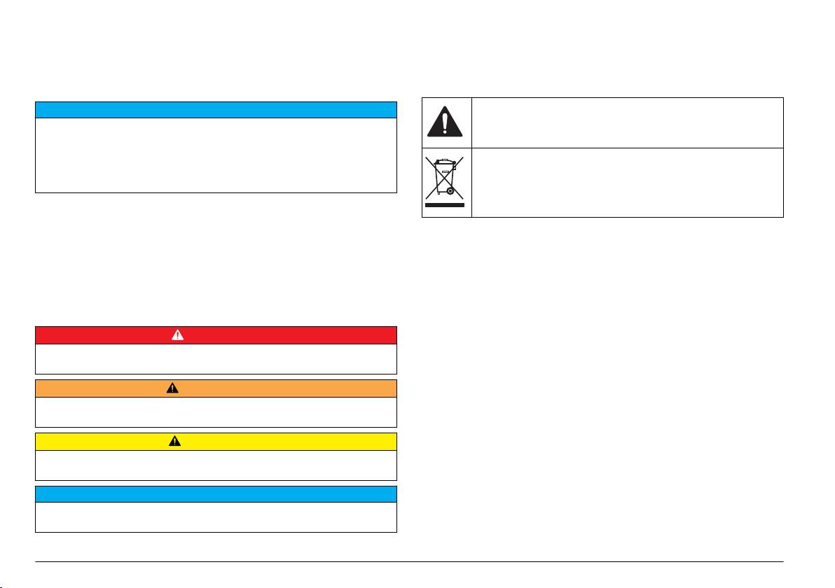
Precautionary labels
Revised editions are found on the manufacturer’s website.
Read all labels and tags attached to the instrument. Personal injury or
damage to the instrument could occur if not observed. A symbol on the
Safety information
instrument is referenced in the manual with a precautionary statement.
N O T I C E
This symbol, if noted on the instrument, references the instruction
manual for operation and/or safety information.
The manufacturer is not responsible for any damages due to misapplication or
misuse of this product including, without limitation, direct, incidental and
consequential damages, and disclaims such damages to the full extent permitted
Electrical equipment marked with this symbol may not be disposed of
under applicable law. The user is solely responsible to identify critical application
in European domestic or public disposal systems. Return old or end-
risks and install appropriate mechanisms to protect processes during a possible
of-life equipment to the manufacturer for disposal at no charge to the
equipment malfunction.
user.
Please read this entire manual before unpacking, setting up or operating
this equipment. Pay attention to all danger and caution statements.
Failure to do so could result in serious injury to the operator or damage
to the equipment.
Product overview
Make sure that the protection provided by this equipment is not impaired.
The sensION
™
+ meters are used with probes to measure various
Do not use or install this equipment in any manner other than that
parameters in water.
specified in this manual.
The sensION
™
+ MM374 meter has two measurement channels to
measure pH, ORP (mV), conductivity or ISE (concentration) with a
Use of hazard information
selective probe. Channel 1 measures one or two parameter individual or
simultaneously and up to two probes can be connected. Channel
D A N G E R
2 measures pH, ORP (mV) or ISE. Measurement data can be stored and
Indicates a potentially or imminently hazardous situation which, if not avoided, will
transferred to a printer or PC.
result in death or serious injury.
Product components
W A R N I N G
Refer to Figure 1 to make sure that all components have been received.
Indicates a potentially or imminently hazardous situation which, if not avoided,
If any items are missing or damaged, contact the manufacturer or a
could result in death or serious injury.
sales representative immediately.
C A U T I O N
Indicates a potentially hazardous situation that may result in minor or moderate
injury.
N O T I C E
Indicates a situation which, if not avoided, may cause damage to the instrument.
Information that requires special emphasis.
4
English
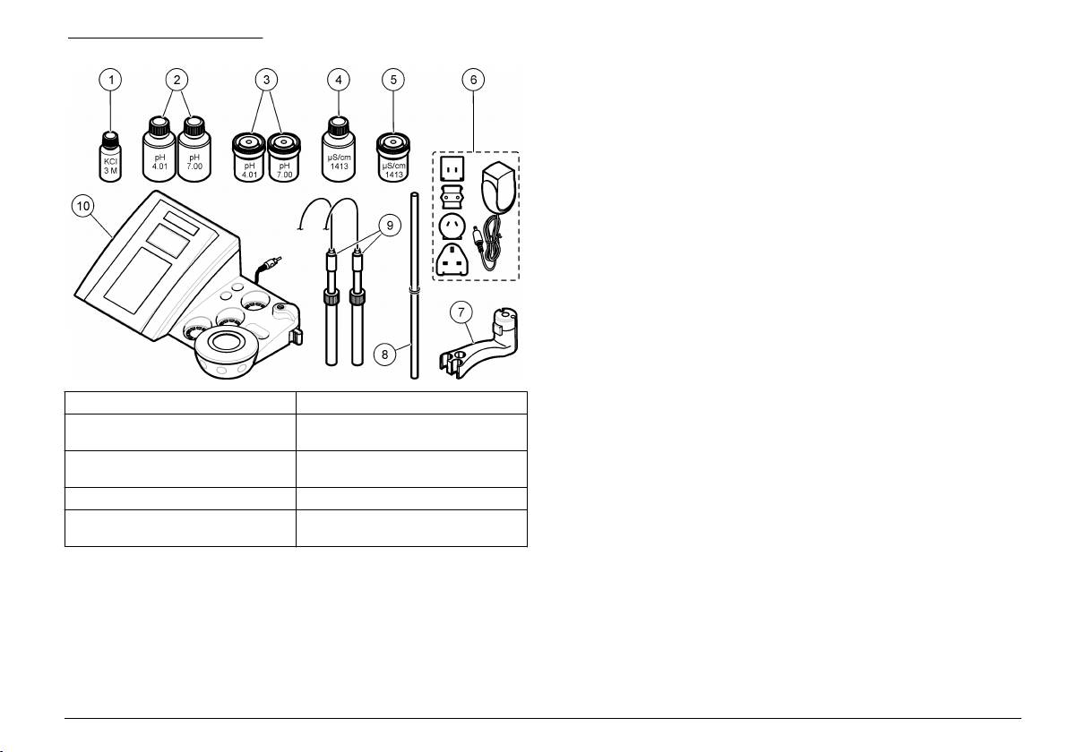
Figure 1 Meter components
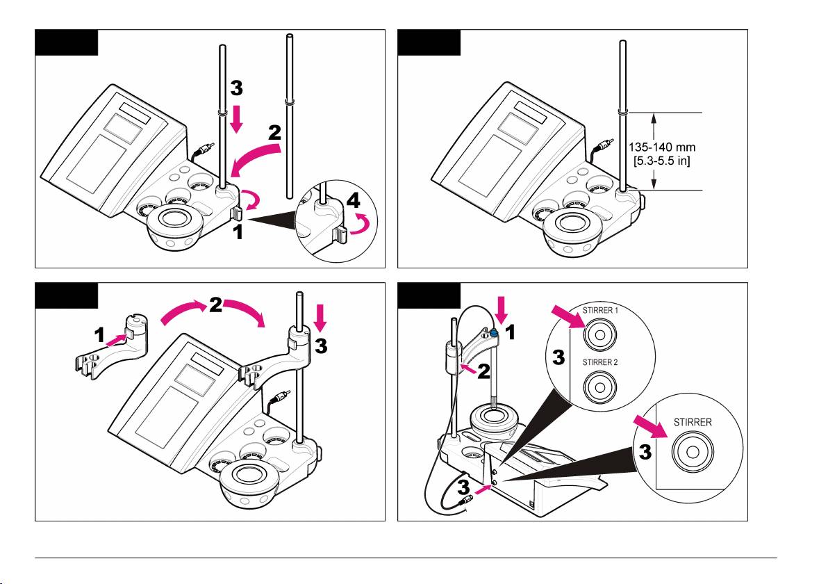
Installation
Assemble the probe holder
Follow the numbered steps to assemble the probe holder and to connect
the magnetic stirrer.
1 Electrolyte for the probe 6 Power supply
2 Buffer solutions (pH 4.01 and pH
7 Probe holder
7.00)
3 Calibration beakers (with magnetic
8 Rod
bar inside)
4 Standard solution (1413 µS/cm) 9 Probes (included with kits only)
5 Calibration beaker (with magnetic
10 Meter
bar inside)
English 5
1 2
3 4
6 English
Connect to AC power
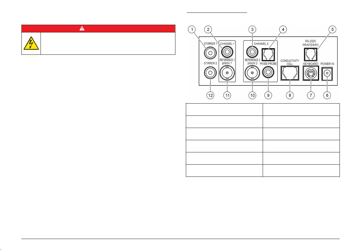
Figure 2 Connector panel
D A N G E R
Electrocution hazard. If this equipment is used outdoors or in
potentially wet locations, a Ground Fault Circuit Interrupt (GFCI/GFI)
device must be used to connect the equipment to its main power
source.
The meter can be powered by AC power with the universal power
adapter.
1. Select the correct adapter plug for the power outlet from the adapter
kit.
2. Connect the universal power adapter to the meter (Figure 2).
3. Connect the universal power adapter to an AC receptacle (Figure 3).
4. Turn the meter on.
1 Magnetic stirrer 1 connector,
7 PC keyboard, mini DIN connector
Channel 1
2 Reference electrode (separated
8 Conductivity probe connector,
electrodes) connector, Channel 1
Channel 2
3 Reference electrode (separated
9 Temperature probe connector,
electrodes) connector, Channel 2
Channel 2
4 Separated temperature probe
10 Combined pH electrode (or
connector, Channel 2
indicator) connector, Channel 2
5 RS-232 for printer or PC connector 11 Combined pH electrode (or
indicator) connector, Channel 1
6 Power supply 12 Magnetic stirrer 2 connector,
Channel 1
English 7
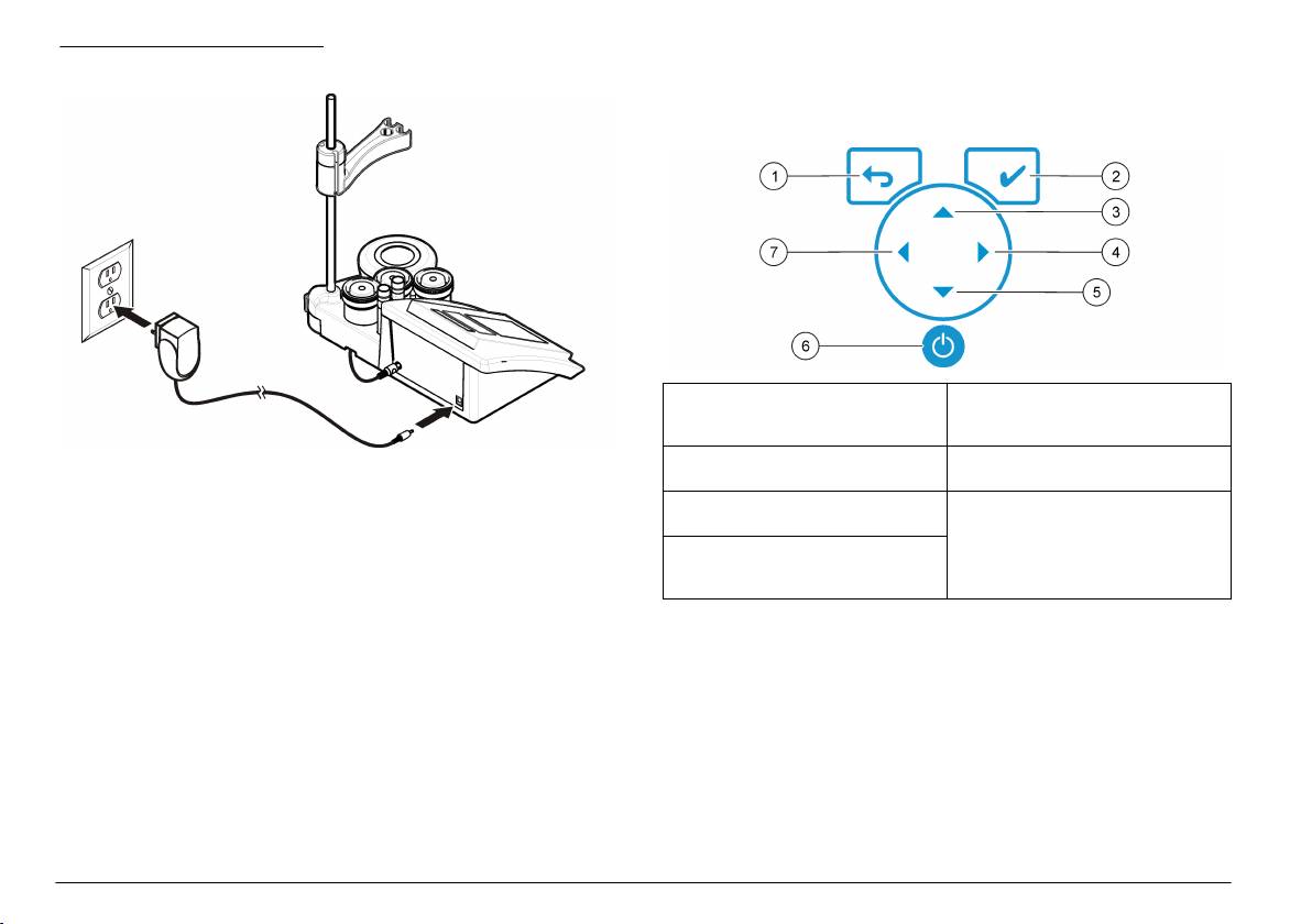
Figure 3 AC power connection
User interface and navigation
User interface
Keypad description
1 RETURN key: cancel or exit the
5 DOWN key: scroll to other options,
current menu screen to the
change a value
previous menu screen
Note: Position the equipment so it is not difficult to disconnect power to the
2 MEASUREMENT key: confirm the
6 ON/OFF: turn on or turn off the
equipment.
selected option
meter
3 UP key: scroll to other options,
7 LEFT key: change between
change a value
Channel 1 and Channel 2, enter
numbers and letters
4 RIGHT key: change between
Channel 1 and Channel 2, enter
numbers and letters
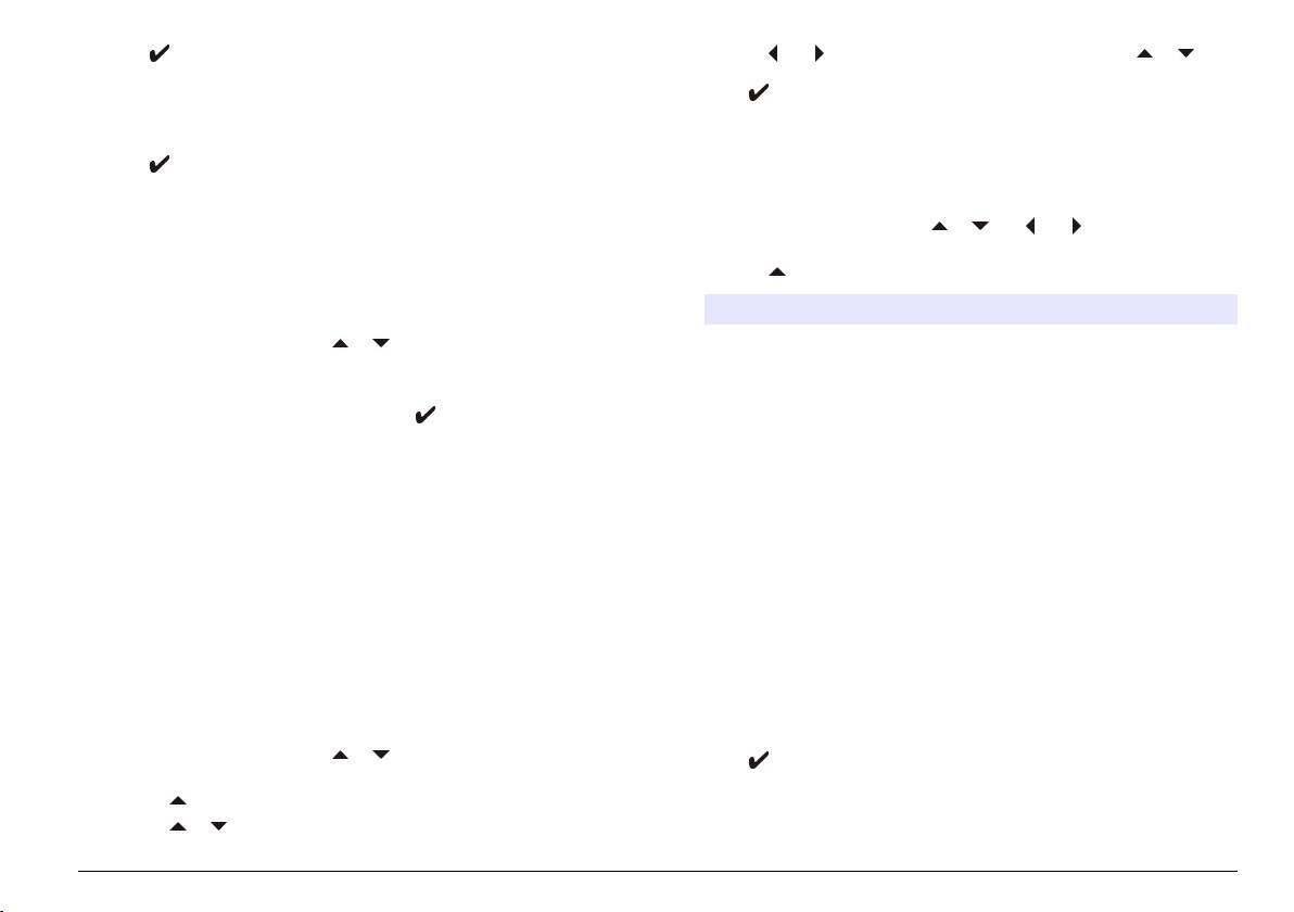
Display description
The meter display shows the concentration, units, temperature,
calibration status, operator ID, sample ID, date and time.
8
English
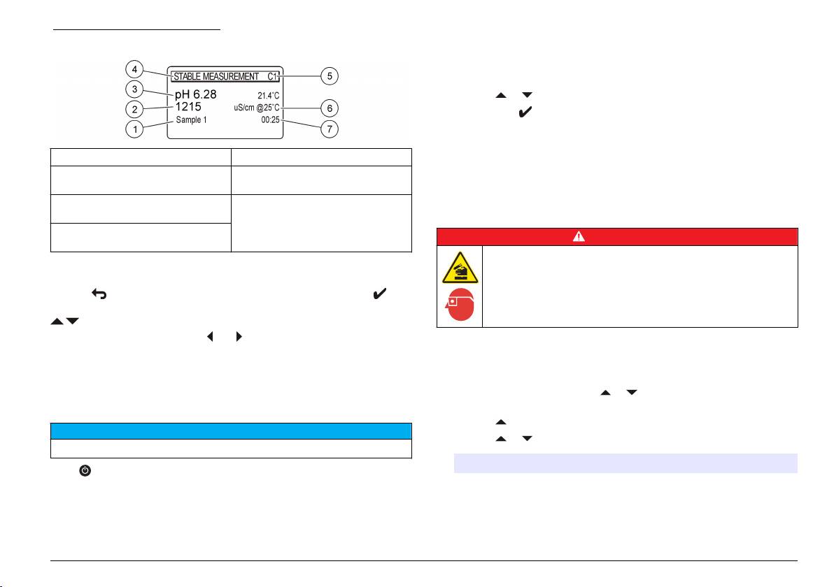
Figure 4 Single screen display
Change the language
The display language is selected when the meter is powered on for the
first time.
1. Use the or to select a language from a list.
2. Confirm with . The measurement screen shows DATA OUTPUT.
3. Select Deactivated if no printer or PC is connected and confirm.
Refer to Select the data output on page 12 for more information
1 Sample ID 5 Measurement channel
about Data Output.
2 Measurement unit and value
6 Sample temperature (ºC or ºF)
(conductivity or ISE)
Standard operation
3 Measurement unit and value (pH,
7 Visual measurement timer
ORP/mV)
Calibration
4 Measurement mode or time and
D A N G E R
date
Chemical exposure hazard. Obey laboratory safety procedures and
Navigation
wear all of the personal protective equipment appropriate to the
Use the to return to the previous menu. Use the measure key to
chemicals that are handled. Refer to the current safety data sheets
(MSDS/SDS) for safety protocols.
take a sample measurement or to confirm options. Use the arrow keys
to scroll to other options or to change a value. To change the
parameters use the arrow keys and . Refer to each task for specific
Calibration settings
instructions.
The calibration settings contain Calibration type, Calibration frequency
and Display options.
Startup
1. From the main menu use the or to select CALIBRATION.
Turn the meter on and off
Confirm.
2. Use the to enter the calibration menu.
N O T I C E
3. Use the or to select the following options:
Make sure that the probe is connected to the meter before the meter is turned on.
Option Description
Push to turn on or turn off the meter. If the meter does not turn on,
make sure that the AC power supply is properly connected to an
Stability C.: Criterion by stability—select Fast, Standard or Strict.
electrical outlet.
English 9

Option Description
Option Description
Calibration
pH: Calibration type—select Technical buffers,
Theoretical calibration pH: The probe calibration data is replaced at
type
DIN19266 Buffers, User Buffers, To a X value, data
25 °C (77 °F). EC: The probe calibration data is
introduction or Theoretical calibration.EC: Calibration type
replaced with C=1.000 cm
-1
—select Molar Standards, Demal Standards, NaCl
Standards, Calibration to a X value, data introduction or
Molar Standards 147 µS/cm, 1413 µS/cm, 12.88 mS/cm and
Theoretical calibration. Refer to Calibration types for more
111.8 mS/cm at 25 °C (77 °F)
information.
Demal Standards 1049 µS/cm, 12.85 mS/cm and 111.31 mS/cm at
Cal. frequency Calibration reminder—can be set between 0–7 days
25 °C (77 °F)
(default daily). The display shows the remaining time to
NaCl Standards 1014.9 µS/cm 25 °C (77 °F)
the new calibration. Refer to Set the calibration reminder
on page 11 for more information.
Calibration procedure
Display mV Display mV—select YES or NO to show mV.
This procedure is for general use with liquid calibration solutions. Refer
to the documents that are included with each probe for additional
Calibration types
information.
Different calibration types can be selected.
Note: Solutions should be stirred during calibration. For more information about the
stirring settings, refer to Change the stirring settings on page 13.
1. From the main menu use the or to select CALIBRATION.
Note: If Channel 1 is used as a double channel (pH and EC) the temperature will
Confirm.
be measured by the conductivity cell with integrated ATC. The conductivity cell
2. Use the to enter the calibration menu.
must be immersed in the pH buffer solution as well during the pH calibration.The
manual temperature modification is not possible.
3. Use the or to select Calibration type.
Option Description
1. Pour the buffers or calibration solutions into the labeled calibration
beakers.
Technical buffers pH 2.00, 4.01, 7.00, 9.21 and 10.01 at 25 °C
(77 °F)
2. From the main menu use the or and and to select the
CALIBRATION parameter. Confirm.
DIN19266 Buffers pH 1.679, 4.006, 6.865, 7.000, 9.180, 10.012 and
12.454
3. If required select the Operator ID (1 to 10) and confirm.
4. Rinse the probe with deionized water and put the probe into the first
User Buffers Selected when the technical or DIN19266 buffers
calibration beaker. Be sure that there are no air bubbles in the
are not used. Refer to Technical buffer solutions
(DIN 19267) on page 19 for pH values of
membrane.
specific buffer sets at varying temperatures.
5. Push to Start calibration.
Calibration to a X value To adjust manually any scale value of the
6. Push to measure the first calibration solution.
measured pH or conductivity.
The next calibration solution is shown.
Data introduction Manual probe constant introduction.
7. Rinse the probe with deionized water and put the probe into the
second calibration beaker. Be sure that there are no air bubbles in
the membrane.
10
English
8. Push to measure the second calibration solution.
4. Use the and to advance to the next step and use the or to
The next calibration solution is shown.
change a value. Confirm.
Push to start the calibration.
9. Rinse the probe with deionized water and put the probe into the third
calibration beaker. Be sure that there are no air bubbles in the
membrane.
Sample measurements
10. Push to measure the third calibration solution.
Each probe has specific preparation steps and procedures for taking
When the calibration is good, the display briefly shows Calibration
sample measurements.
OK and then returns to the main menu.
Note: When a printer is connected the print menu opens and the result can be
1. From the main menu use the or and and to select
printed.
MEASURE. Confirm.
2. Use the to change the following settings. Confirm every entry.
View the calibration data
Data from the most recent calibration can be shown.
Option Description
Resolution Select the resolution: 1, 0.1, 0.01 (default) or 0.001
1. From the main menu use the or to select DATA LOGGER.
Confirm.
Measure Stability—select By stability Criterion: Fast (variation <
2. Select Display data.
0.02 pH in 6 s), Standard (variation < 0.01 pH in 6 s) or Strict
(variation < 0.002 pH in 6 s). In continuous—enter the time
3. Select Calibration data and confirm with . The last calibration data
interval for the In continuous Acquis. interval (data storage or
is shown.
printing data). By time—enter the time interval for data storage
or printing data.
• pH-the slope and offset values are shown alternating with the
deviation (in %) and calibration temperature.
Display mV Display mV—select YES or NO to show mV.
• ORP-the measured mV value and calibration temperature are
Limits Limits—select YES or NO. YES: Enter the upper and lower
shown.
limits. An acoustic warning appears when the measurement is
• Conductivity-the cell constant and calibration temperature for each
out of limit. The report output shows an A next to the
measured value when the measurement was out of limit.
standard are shown.
Isopotential Isopotential—change the Isopotential pH value in Data
Set the calibration reminder
introduction. Select Calculate to calibrate the probe again.
pH: The calibration reminder can be set between 0 to 23 hours or
TC TC—select Linear or Natural waters. Linear: enter a value in
1-7 days (default 1 day). EC: The calibration reminder can be set
%/°C (default 2.00%/Temperature). Natural waters: Non-linear
between 0 to 99 days (default 15 days). The display shows the
for natural waters, according to EN27888
remaining time to the new calibration.
Note: When 0 days is selected, the calibration reminder is turned off.
Tref Reference temperature—select between 20 or 25 °C or Other
temperature.
1. From the main menu use the or to select CALIBRATION.
3. Push to start the measurement.
Confirm.
Note: If the measurement is not stabilizing after 120 seconds, the meter turns
2. Use the to enter the calibration menu.
automatically into the continuous measurement mode.
3. Use the or to select Cal. frequency and confirm.
English
11

Advanced operation
1. From the main menu use the or to select SYSTEM. Confirm.
Change the measurement units
2. Use the or to select Data Output and confirm.
3. Use the or to select
The measurement units can be changed individually for each channel.
Option Description
1. From the main menu use the or to select SYSTEM. Confirm.
Deactivated Select Deactivated if no printer or PC is connected.
2. Use the or to select Measurement units and confirm.
3. Select Channel 1 and confirm.
For Printer Select Dot matrix printer or Thermal printer.
4. Select Parameter 1 and then Parameter 2 and select one of the
For Computer Select Terminal, LabCom or LabCom Easy. The LabCom
following options:
Software controls several modules, pH and conductivity
meters, automatic burettes, Samplers and so on from a
Option Description
computer. The LabCom Easy software gets measurements
and calibration data from the meters
Parameter 1 mV, pH, ISE or Disabled
Parameter 2 EC, NaCl, TDS, Ω or Disabled
Change the date and time
5. Select Channel 2 and confirm with . Select mV, pH or ISE and
The date and time can be changed from the Date / Time menu.
confirm.
1. From the main menu use the or to select SYSTEM. Confirm.
Use a sample ID
2. Use the or to select Date / Time and confirm.
The sample ID tag is used to associate readings with a particular sample
3. Use the and to advance to the next step and use the or to
location. If assigned, stored data will include this ID.
change a value. Confirm.
The current date and time will be shown on the display.
1. From the main menu use the or to select SYSTEM. Confirm.
2. Use the or to select Sample ID and confirm.
Adjust the display contrast
3. Use the or to select
1. From the main menu use the or to select SYSTEM. Confirm.
Option Description
2. Use the or to select Display contrast and confirm.
Automatic A consecutive number will be automatically assigned to every
3. Use the and to adjust the contrast of the display and confirm.
sample.
Manual A keyboard or a barcode scanner is required to enter the
Adjust the temperature
sample ID name before taking a measurement (maximum
15 characters).
The temperature measurement can be adjusted at 25 °C (77 °F) and/or
85 °C (185 °F) to increase accuracy.
Select the data output
Data can be stored or transferred to a printer or to a PC.
12
English

4. When the stirrer is turned on, use the or to change the stirring
1. Put the probe and a reference thermometer in a container of water at
speed in %.
approximately 25 °C and allow the temperature to stabilize.
Note: Use the or to change the stirring speed during calibration and
2. Compare the temperature read by the meter with that of the
during a measurement.
reference thermometer. The difference is the adjustment value for
the meter.
Turn the stirrer on or off
Example: reference thermometer: 24.5 °C; meter: 24.3 °C.
The stirrer 1 works with Channel 1 and 2 (Stirrer 1). A second stirrer can
Adjustment value: 0.2 °C.
be connected to channel 2 (Stirrer 2). For the stirrer 2 activation refer to
3. Enter the adjustment value for the 25 °C reading:
the following steps.
a. From the main menu use the or to select SYSTEM. Confirm.
1. From the main menu use the or to select SYSTEM. Confirm
b. Use the or to select Readjust temp. and confirm.
with .
c. Select Channel 1 or Channel 2 and confirm. The temperature for
2. Use the or to select Stirrer N.2 and confirm with .
channel 1 is measured by the conductivity cell and channel 2 is
3. Use the or to select YES to turn the stirrer 2 on.
measured by the pH probe. If no Conductivity cell is connected,
Note: Select NO to turn the stirrer 2 off.
the temperature value must be entered manually or the
temperature measured in channel 2 can be applied to the meter.
Change the temperature units
d. Use the or to select 25 °C and confirm.
e. Use the arrow keys to enter the adjustment value for 25 °C.
The temperature units can be changed to Celsius or Fahrenheit.
Confirm.
1. From the main menu use the or to select SYSTEM. Confirm.
4. Put the probe and a reference thermometer in a container of water at
approximately 85 °C and allow the temperature to stabilize.
2. Use the or to select Temperature units and confirm.
5. Compare the temperature from the meter with that of the reference
3. Use the or to select between Celsius or Fahrenheit and confirm.
thermometer. The difference is the adjustment value for the meter.
Data logger
a. Use the or to select 85 °C and confirm.
b. Use the arrow keys to enter the adjustment value for 85 °C.
Display data
Confirm.
c. Select Save changes and confirm.
The Display data log contains Measurement data, Electrode report and
Calibration data. The stored data can be sent to a printer or to a PC.
Change the stirring settings
When the data log becomes full (400 data points), the oldest data point
is deleted when a new data point is added.
The magnetic stirrer can be turned on and the stirring speed can be
changed in the Stirring menu.
1. From the main menu use the or to select SYSTEM. Confirm.
2. Use the or to select Stirring and confirm.
3. To turn on/off the stirrer push .
English
13
1. From the main menu use the or to select DATA LOGGER and
data, Electrode data, Calibration data, Calibration report or
confirm.
Instrument condit.
2. Use the or to select Display data and confirm.
Report output
3. Use the or to select
Option Description
N O T I C E
Measurement data Measurement data—stores automatically each time a
The data output (printer or PC) needs to be selected first, so that the Type of
sample is measured
report menu is available (refer to Select the data output on page 12).
Electrode report Electrode report—stores automatically the electrode
Different report output types can be selected when a printer or a PC is
history and measurement conditions
connected.
Calibration data Calibration data—stores automatically the current
1. From the main menu use the or to select SYSTEM. Confirm.
calibration
2. Use the or to select Type of report and confirm.
Delete data
3. When a printer or a computer and Terminal is connected, use the
or to select
The entire measurement data or electrode report log can be deleted to
remove data that has already been sent to a printer or PC.
Option Description
Reduced Select Several or One sample as an output format
1. From the main menu use the or to select DATA LOGGER and
confirm.
2. Use the or to select Erase and confirm.
3. Use the or to select Measurement data or Electrode report and
confirm. Confirm again to delete the data.
The entire log is deleted at once.
Send data to a printer or to a computer
N O T I C E
The data output (printer or PC) needs to be selected first, so that the Print menu
is available (refer to Select the data output on page 12).
Note: Refer to Report output on page 14 to select the report output type.
1. From the main menu use the or to select DATA LOGGER and
confirm.
2. Use the or to select Print and confirm. Select one of the
following options and confirm with to print the data: Measurement
14 English
Option Description
C A U T I O N
Standard Select Several or One sample as an output format. Select
Personal injury hazard. Only qualified personnel should conduct the tasks
several: Users: The user name appears on the printed report
described in this section of the manual.
(17 characters). Header:The company name can be added as a
header (40 characters) and appears on the print report. Identify
Clean the instrument
sensor:The sensor model and the sensor serial number can be
added and appears on the print report.
N O T I C E
GLP Select Several or One sample as an output format. Select
Never use cleaning agents such as turpentine, acetone or similar products to
several: Users: The user name appears on the printed report
clean the instrument including the display and accessories.
(17 characters). Header:The company name can be added as a
header (40 characters) and appears on the print report. Identify
Clean the exterior of the instrument with a moist cloth and a mild soap
sensor:The sensor model and the sensor serial number can be
solution.
added and appears on the print report.
4. When a computer is connected and LabCom Easy (refer to Select
Clean the probe
the data output on page 12 for more information) is selected, use the
Clean the probe as needed. Refer to Troubleshooting on page 17 for
or to select
more information about cleaning. Refer to the probe documentation for
Option Description
information about the probe maintenance.
Users The user name appears on the printed report
Replace the magnetic stirrer
(17 characters).
If the magnetic stirrer does not start, follow the numbered steps to
Identify sensor The sensor model and the sensor serial number can be
added and appears on the print report.
replace the magnetic stirrer.
Maintenance
W A R N I N G
Multiple hazards. Do not disassemble the instrument for maintenance or service.
If the internal components must be cleaned or repaired, contact the
manufacturer.
English 15
