Hach-Lange POLYMETRON 9611 sc Installation: инструкция
Раздел: Техника
Тип:
Инструкция к Hach-Lange POLYMETRON 9611 sc Installation

DOC023.98.80270
3–
Polymetron 9611sc PO
4
08/2013, Edition 2
Installation
Installation
Installazione
Installation
Instalación
Instalação
Instalace
Installation
Installatie
Instalacja
Installation
Asentaminen
Инсталиране
Telepítés
Instalarea
Montavimas
Монтаж
Kurulum
Inštalácia
Namestitev
Ugradnja
Εγκατάσταση
Paigaldamine

English...................................................................................................................................................................................................3
Deutsch...............................................................................................................................................................................................19
Italiano.................................................................................................................................................................................................37
Français..............................................................................................................................................................................................54
Español...............................................................................................................................................................................................72
Português..........................................................................................................................................................................................89
Čeština..............................................................................................................................................................................................107
Dansk.................................................................................................................................................................................................124
Nederlands......................................................................................................................................................................................141
Polski.................................................................................................................................................................................................158
Svenska............................................................................................................................................................................................175
Suomi.................................................................................................................................................................................................192
български.......................................................................................................................................................................................209
Magyar..............................................................................................................................................................................................227
Română............................................................................................................................................................................................244
lietuvių kalba...................................................................................................................................................................................261
Русский............................................................................................................................................................................................278
Türkçe................................................................................................................................................................................................296
Slovenský jazyk............................................................................................................................................................................312
Slovenski..........................................................................................................................................................................................329
Hrvatski.............................................................................................................................................................................................346
Ελληνικά...........................................................................................................................................................................................362
eesti keel..........................................................................................................................................................................................380
2
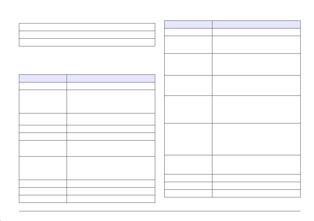
Table of contents
Table 1 General specifications (continued)
Specification Details
Specifications on page 3
Maximum altitude 2000 m (6560 ft)
General information on page 4
4–20 mA outputs Four; load impedance: 600 Ω maximum
Installation on page 7
Connection: 22 to 16 AWG wire, 22 to 20 AWG
recommended, twisted pair shielded wire
Specifications
Alarm relay outputs Four; type: not powered SPDT relays, each rated at
5 A resistive, 240 VAC maximum
Specifications are subject to change without notice.
Connection: 18 to 16 AWG wire, 18 AWG stranded
Table 1 General specifications
recommended
Specification Details
Digital inputs Four; connection: 22 to 16 AWG wire, 22 to
20 AWG stranded (isolated DC voltage input or an
Dimensions (W x D x H) 452 x 360 x 804 mm (17.8 x 14.2 x 31.7 in.)
open-collector/relay contact closure input)
recommended
Enclosure Rating: NEMA 4x/IP65
Material: PC/ABS case, PC door, PC hinges and
Fuses Input power—AC: T 1.6 A, 250 VAC; DC: T 6.3 A,
latches, 316 SST hardware
250 VAC
Indoor use only. Keep away from direct sunlight.
Output power—AC: T 5.0 A, 250 VAC; DC: T 1.6 A,
250 VAC
Weight 20 kg (45 lb) without reagents and standards,
Alarm relay outputs: T 5.0 A, 250 V
36.3 kg (80 lb) with reagents
Fittings Sample line and sample bypass drain: 6 mm OD
Mounting Wall, panel or table
push-to-connect fitting for plastic tubing
Protection class I
Air purge air inlet: 6 mm OD push-to-connect fitting
for plastic tubing
Pollution
2/II
degree/installation
Chemical and case drains: 11 mm (7/16 in.) ID slip-
category
on fitting for soft plastic tubing
Power requirements AC: 100–240 VAC, 50/60 Hz
Sample pressure, flow
Pressure: 2–87 psi to preset pressure regulator
rate, and temperature
Instrument: 0.5 A nominal, 2.6 A maximum
Flow rate: 55–300 mL/minute
Connection: 18 to 16 AWG wire, 18 AWG stranded
Temperature: 5 to 50 °C (41 to 122 °F)
recommended
Number of sample streams 1, 2 or 4; programmable sequence
Operating temperature 5 to 45 °C (41 to 113 °F)
Air purge (optional) 0.425 m
3
/hour (15 scfh
1
), instrument quality air
Operating humidity 5 to 95% non-condensing
Certifications ETL certified to UL and CSA standards, CE marked
Storage temperature –20 to 60 °C (–4 to 140 °F)
1
standard cubic feet per hour
English
3
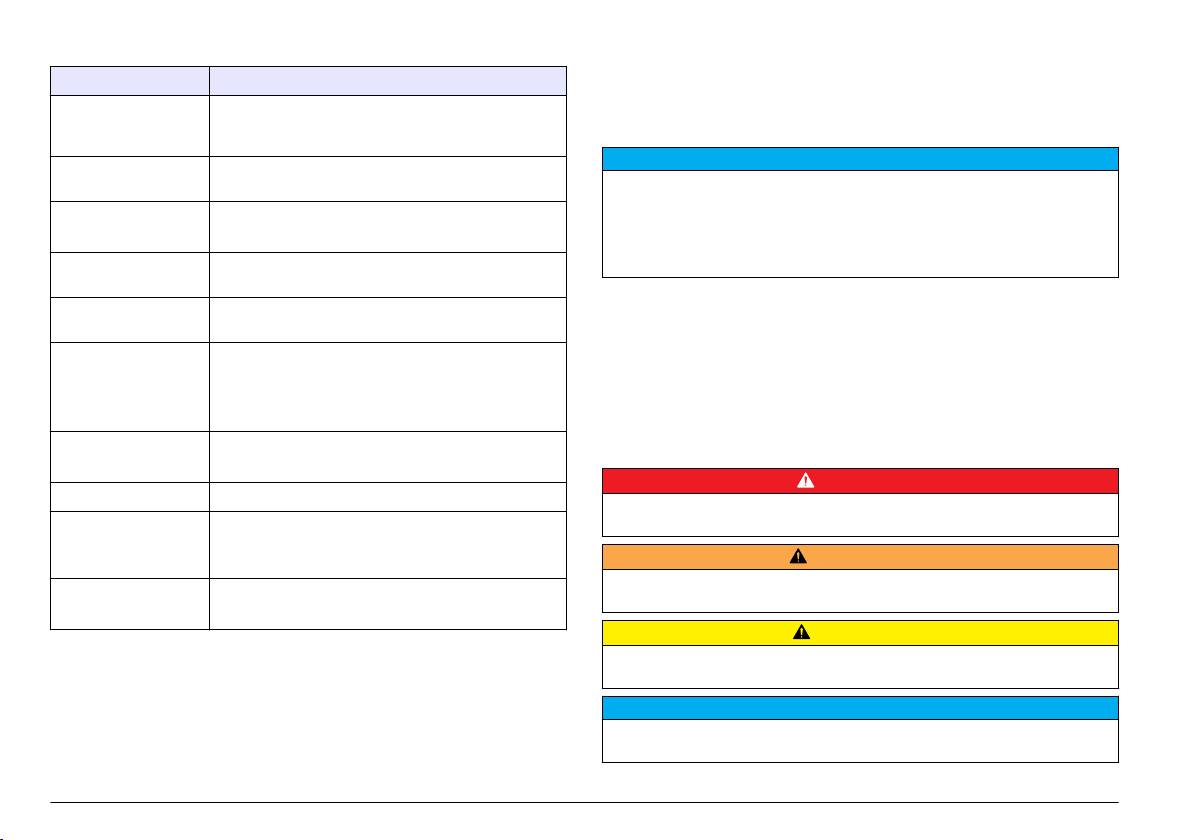
Table 2 Measurement specifications
changes in this manual and the products it describes at any time, without
notice or obligation. Revised editions are found on the manufacturer’s
Specification Details
website.
Light source Class 1M LED (light emitting diode) with a peak
wavelength of 480 nm (LR model) or 880 nm (HR
Safety information
model)
N O T I C E
Measurement range 4–3000 µg/L as PO
4
(LR model); 200–50,000 µg/L as
PO
4
(HR model)
The manufacturer is not responsible for any damages due to misapplication or
misuse of this product including, without limitation, direct, incidental and
Accuracy
1
LR model: ±4 µg/L or ±4% (the larger value)
consequential damages, and disclaims such damages to the full extent permitted
under applicable law. The user is solely responsible to identify critical application
HR model: ±500 µg/L or ±5% (the larger value)
risks and install appropriate mechanisms to protect processes during a possible
Precision/Repeatability LR model: ±1%, HR model: ±500 µg/L or ±5% (the
equipment malfunction.
larger value)
Please read this entire manual before unpacking, setting up or operating
Response time Typical 10 minutes at 25 °C (77 °F), changes with
this equipment. Pay attention to all danger and caution statements.
temperature
Failure to do so could result in serious injury to the operator or damage
to the equipment.
Stabilization time After initial startup or annual maintenance:
5 measurement cycles
Make sure that the protection provided by this equipment is not impaired.
After standby: 1 measurement cycle
Do not use or install this equipment in any manner other than that
specified in this manual.
After calibration: 0 measurement cycles
Calibration time Slope calibration: 10 minutes
Use of hazard information
Zero calibration: 10 minutes
D A N G E R
Minimum detection limit LR model: 4 µg/L, HR model: 200 µg/L
Indicates a potentially or imminently hazardous situation which, if not avoided, will
Reagent usage Usage: 2 L of each reagent every 90 days with a
result in death or serious injury.
15 minute cycle time
Container: 2 L, PETE with polypropylene caps
W A R N I N G
Indicates a potentially or imminently hazardous situation which, if not avoided,
Standard usage Usage: 2 L of standard for every 10 calibrations
could result in death or serious injury.
Container: 2 L, PETE with polypropylene caps
C A U T I O N
1
The accuracy is based on using Hach supplied reagents only.
Indicates a potentially hazardous situation that may result in minor or moderate
injury.
General information
N O T I C E
In no event will the manufacturer be liable for direct, indirect, special,
Indicates a situation which, if not avoided, may cause damage to the instrument.
incidental or consequential damages resulting from any defect or
Information that requires special emphasis.
omission in this manual. The manufacturer reserves the right to make
4 English
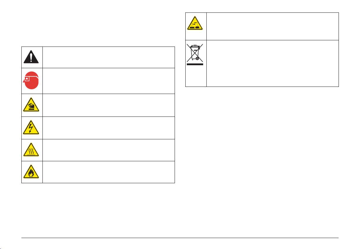
Precautionary labels
This symbol identifies the presence of a strong corrosive or other
hazardous substance and a risk of chemical harm. Only individuals
Read all labels and tags attached to the instrument. Personal injury or
qualified and trained to work with chemicals should handle chemicals
damage to the instrument could occur if not observed. A symbol, if noted
or perform maintenance on chemical delivery systems associated
on the instrument, will be included with a danger or caution statement in
with the equipment.
the manual.
Note: For return for recycling, please contact the equipment producer or supplier
for instructions on how to return end-of-life equipment, producer-supplied
This is the safety alert symbol. Obey all safety messages that follow
electrical accessories, and all auxiliary items for proper disposal.
this symbol to avoid potential injury. If on the instrument, refer to the
Electrical equipment marked with this symbol may not be disposed of
instruction manual for operation or safety information.
in European public disposal systems after 12 August of 2005. In
conformity with European local and national regulations (EU Directive
This symbol indicates the need for protective eye wear.
2002/96/EC), European electrical equipment users must now return
old or end-of-life equipment to the Producer for disposal at no charge
to the user.
This symbol identifies a risk of chemical harm and indicates that only
Certification
individuals qualified and trained to work with chemicals should handle
Canadian Radio Interference-Causing Equipment Regulation,
chemicals or perform maintenance on chemical delivery systems
IECS-003, Class A:
associated with the equipment.
Supporting test records reside with the manufacturer.
This symbol indicates that a risk of electrical shock and/or
electrocution exists.
This Class A digital apparatus meets all requirements of the Canadian
Interference-Causing Equipment Regulations.
Cet appareil numérique de classe A répond à toutes les exigences de la
This symbol indicates that the marked item can be hot and should not
réglementation canadienne sur les équipements provoquant des
be touched without care.
interférences.
FCC Part 15, Class "A" Limits
Supporting test records reside with the manufacturer. The device
This symbol indicates that a risk of fire is present.
complies with Part 15 of the FCC Rules. Operation is subject to the
following conditions:
1. The equipment may not cause harmful interference.
2. The equipment must accept any interference received, including
interference that may cause undesired operation.
Changes or modifications to this equipment not expressly approved by
the party responsible for compliance could void the user's authority to
operate the equipment. This equipment has been tested and found to
comply with the limits for a Class A digital device, pursuant to Part 15 of
the FCC rules. These limits are designed to provide reasonable
English
5
protection against harmful interference when the equipment is operated
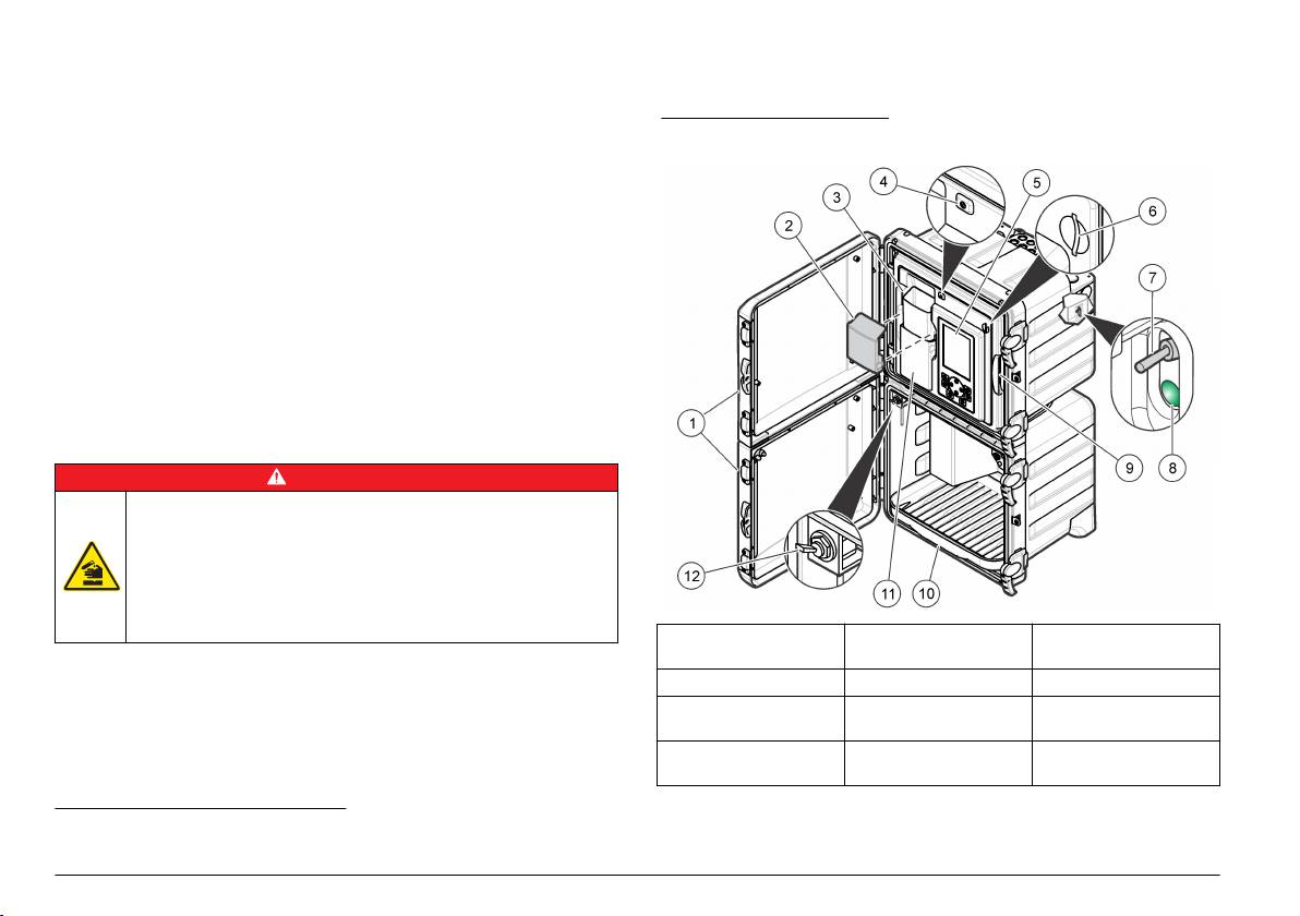
Refer to Figure 1 for the analyzer overview. The doors can be easily
in a commercial environment. This equipment generates, uses and can
removed for better access. Refer to Figure 2.
radiate radio frequency energy and, if not installed and used in
accordance with the instruction manual, may cause harmful interference
to radio communications. Operation of this equipment in a residential
Figure 1 Product overview
area is likely to cause harmful interference, in which case the user will be
required to correct the interference at their expense. The following
techniques can be used to reduce interference problems:
1. Disconnect the equipment from its power source to verify that it is or
is not the source of the interference.
2. If the equipment is connected to the same outlet as the device
experiencing interference, connect the equipment to a different
outlet.
3. Move the equipment away from the device receiving the interference.
4. Reposition the receiving antenna for the device receiving the
interference.
5. Try combinations of the above.
Product overview
D A N G E R
Chemical or biological hazards. If this instrument is used to monitor a
treatment process and/or chemical feed system for which there are
regulatory limits and monitoring requirements related to public health,
public safety, food or beverage manufacture or processing, it is the
responsibility of the user of this instrument to know and abide by any
applicable regulation and to have sufficient and appropriate
mechanisms in place for compliance with applicable regulations in the
event of malfunction of the instrument.
1 Upper and lower
5 Display and keypad 9 Analytics panel
doors
The analyzer measures high or low range phosphate concentration in
power water and industrial water. The high range phosphate
2 Funnel cover 6 SD card slot 10 Reagent bottle tray
measurement uses the molybdovanadate method. The low range
3 Grab sample input
7 Power switch 11 Colorimeter cover
phosphate measures low levels of orthophosphate and uses the
funnel
ascorbic acid method. Both methods are adapted from Standard
*
Methods.
4 Status indicator light 8 Power LED (on =
12 Grab sample valve
analyzer is on)
*
Standard Methods for the Examination of Water and Wastewater, 21st Edition, 2005, Centennial Edition, APHA, AWWA, WEF. Low Range: 4-153,
4500-P E. Ascorbic Acid Method. High Range: 4-151, 4500-P C. Vanadomolybdophosphoric Acid Colormetric Method.
6 English
