Dell UPS 5600R: Installing the Input and Ground Wires
Installing the Input and Ground Wires: Dell UPS 5600R
Table of contents
- Notes and Warnings
- System Features
- Finding Information What are You Looking For? Find It Here
- Installation and Startup Unpacking the System
- Lifting the Cabinet
- Identifying the UPS Figure 1. The Dell Online Rack UPS Front Panel Figure 2. 5600W, 208V Rear Panel
- Figure 3. 5600W, 230V Rear Panel
- Rackmount Setup Removing the Battery Retaining Bracket
- Removing the Battery Trays
- Installing the Rails
- Installing the Cabinet
- Securing the Cabinet Installing the Battery Trays
- Replacing the Battery Retaining Bracket and Connecting the Internal Battery Connectors
- Installing the UPS Front Cover Connecting the Equipment
- Hardwiring the UPS Input
- Removing the Terminal Block Cover
- Installing the Input and Ground Wires
- Starting the UPS
- Completing the Startup
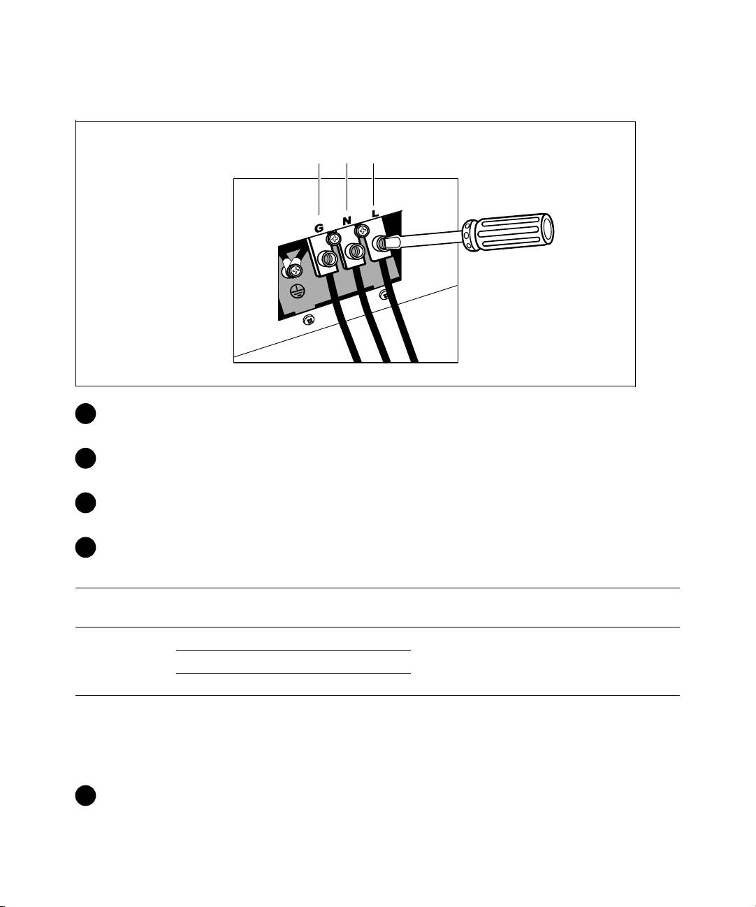
Installing the Input and Ground Wires
Terminal Position
1
2
3
®
3 Punch a hole in the terminal block cover for the input conduit using a Greenlee
punch or similar
device. The hole accommodates 3/4” or 1” IMC conduit.
4 Pull the input wire through the conduit, leaving approximately 2 ft (0.5m) of exposed wire. Attach
a flexible metal fitting to the end of the conduit.
5 Insert the conduit through the wiring access entry and attach the conduit fitting to the panel.
Strip 0.5” (1.5 cm) of insulation from the end of each incoming wire.
6 Connect the input and ground wires to the terminal block according to Table 1.
Table 1. UPS Wiring Specifications
Terminal
Terminal Wire
Wire Function
UPS Wire Function
Tightening Torque
Position
Size Rating*
Input
1 Input Ground
2
5.26–16 mm
2 L2/Neutral In
2.49 Nm (22 lb in)
(10–6 AWG)
3 L1 In
* Use a minimum:
S 10 AWG for equipment grounding wire, 75_C copper wire minimum
S 8 AWG for input line and neutral wires, 75_C copper wire minimum
7 Replace the terminal block cover.
18
|
Installation and Startup
