Nikon 70-200mm-f4G-ED-AF-S-VR-Zoom-Nikkor: En
En: Nikon 70-200mm-f4G-ED-AF-S-VR-Zoom-Nikkor
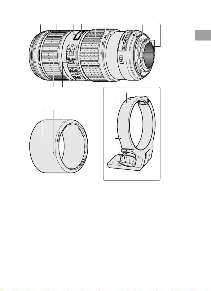
Parts of the Lens
En
13
En_03
w e
r t y u i o !0q
!1 !2 !3 !4
!9!8
!5
!6 !7
@0
■
*
Optional.
q Lens hood mounting mark .......18
!2 Focus limit switch ...........................15
w Focus ring ............................................15
!3 Vibration reduction ON/OFF
e Focus distance indicator
switch ...............................................16
r Focus distance mark
!4 Vibration reduction mode
t Zoom ring ............................................15
switch ...............................................16
y Focal length scale ...........................15
!5 Lens hood ............................................18
u Focal length mark
!6 Lens hood alignment mark ......18
i Lens mounting mark
!7 Lens hood lock mark .....................18
o Rubber lens-mount gasket .......20
!8 Position indices (90°) * ..................19
!0 CPU contacts .....................................20
!9 Tripod collar ring * ..........................19
!1 Focus-mode switch ....................... 15
@0 Tripod collar ring attachment
knob * ............................................... 19

Thank you for your purchase of an AF‑S NIKKOR 70‑200mm f/4G ED VR
lens.
Before using this product, please carefully read both these
instructions and the camera manual.
En
Note: When mounted on a DX-format digital single-lens reflex camera such as
the D7000 or cameras in the D300 series, this lens has an angle of view of
22° 50′ – 8° and a focal length equivalent to 105 – 300 mm (35 mm format).
■
Compatibility
Check marks (“✔“) indicate supported features, dashes (“—”) features
that are not supported.
Some limitations may apply; see the camera
manual for details.
Exposure (Shooting) mode
Function
4
5
6
Camera
P
S A M AF
VR
Nikon FX-format and DX-format digital single-lens reflex cameras,
✔ ✔ ✔ ✔ ✔ ✔
1
1
1
F6, F5, F100, F/N80-series
, F/N75-series
, F/N65-series
1
2
Pronea 600i/6i
, Pronea S
✔ ✔ ✔ ✔ ✔
—
1
1
1
F4-series, F90X/N90s
, F90-series/N90
, F70-series/N70
✔ ✔
— —
✔
—
1
1
1
F60-series/N60
, F/N55-series
, F50-series/N50
, F-401x/
✔ ✔ ✔ ✔
— —
1
1
1
N5005
, F-401s/N4004s
, F-401/N4004
1
1
1
F-801s/N8008s
, F-801/N8008
, F-601m/N6000
✔ ✔
— — — —
1
3
F3AF, F-601/N6006
, F-501/N2020
, Nikon manual focus
—
1
cameras (excluding F-601m/N6000
)
1
N-series cameras and Pronea
3
N2020 sold in U. S. A. and Canada only.
6i sold in U. S. A. only.
4
Includes AUTO and scene (Digital Vari-
2
Exposure mode M (manual)
Program) modes.
not available.
5
Autofocus.
6
Vibration reduction.
■
Focus
Supported focus modes are shown in the following table (for information
on camera focus modes, see the camera manual).
Camera
Lens focus mode
Camera
focus mode
A/M M
Nikon FX-format and DX-format digital single-lens
Autofocus with
Manual focus
reflex cameras, F6, F5, F4-series, F100, F90X/N90s *,
AF
manual override
with electronic
F90-series/N90 *, F/N80-series *, F/N75-series *, F70-
(AF priority)
rangefinder
series/N70 *, F/N65-series *, Pronea 600i/6i *, Pronea S
MF
Manual focus (electronic
F60-series/N60 *, F/N55-series *, F50-series/N50 *,
rangefinder available with all
F-801s/N8008s *, F-801/N8008 *, F-601
m/N6000 *,
AF, MF
cameras except F-601
m/
F-401x/N5005 *, F-401s/N4004s *, F-401/N4004 *
N6000 *)
*
N-series cameras and Pronea 6i sold in U. S. A. only.
14
En_03

A/M (Autofocus with Manual Override/AF Priority)
To focus using autofocus with manual override (A/M):
z
Slide the lens focus-mode switch to A/M.
En
x
Focus.
If desired, autofocus can be over‑ridden by rotating the lens focus
ring while the shutter‑release button is pressed halfway (or, if the
camera is equipped with an AF-ON button, while the AF-ON button
is pressed); note that the ring must be rotated a short distance before
autofocus is over‑ridden.
To refocus using autofocus, press the
shutter‑release button halfway or press the AF-ON button again.
The Focus Limit Switch
This switch determines the focus distance limits for autofocus.
FULL: Select this option for subjects that may be closer than
3 m (9.84 ft).
∞–3 m: If your subject will always be at distance of at least
3 m (9.84 ft), select this option for faster focusing.
■
Zoom and Depth of Field
Before focusing, rotate the zoom ring to adjust the focal length and frame
the photograph.
If the camera offers depth‑of‑field preview (stop down),
depth of field can be previewed in the viewfinder (see page 210 for more
information).
Note: Note that the focus distance indicator is intended only as a guide and
may not accurately show the distance to the subject and may, due to depth
of field or other factors, not show ∞ when the camera is focused on a distant
object.
■
Aperture
Aperture is adjusted using camera controls.
15
En_03

■
Built-in Flash Units
When using the built‑in flash on cameras equipped with a built‑in flash
unit, remove the lens hood to prevent vignetting (shadows created
En
where the end of the lens obscures the built‑in flash).
■
Vibration Reduction
Vibration reduction reduces blur caused by camera shake, allowing
shutter speeds up to five stops slower than would otherwise be the case
(Nikon measurements; effects vary with the photographer and shooting
conditions).
This increases the range of shutter speeds available and
permits hand‑held, tripod‑free photography in a wide range of situations.
Using the Vibration Reduction ON/OFF Switch
Select ON to enable vibration reduction.
Vibration reduction is
activated when the shutter‑release button is pressed
halfway, reducing the effects of camera shake for
improved framing and focus.
Select OFF to turn vibration reduction off.
Using the Vibration Reduction Mode Switch
The vibration reduction mode switch is used to select the vibration
reduction mode when vibration reduction is on.
Select NORMAL to reduce the effects of vibration when
photographing from a fixed position and in other
situations with comparatively little camera motion.
Select ACTIVE to reduce the effects of vibration when
shooting from a moving vehicle, while walking, and in
other situations with active camera motion.
16
En_03

Using Vibration Reduction: Notes
•
Slide the vibration reduction switch to OFF if the camera does not
support vibration reduction (pg. 14).
Leaving vibration reduction on
may greatly increase the drain on the battery, particularly in the case of
En
Pronea 600i/6i cameras.
•
When using vibration reduction, press the shutter‑release button
halfway and wait for the image in the viewfinder to stabilize before
pressing the shutter‑release button the rest of the way down.
•
When vibration reduction is active, the image in the viewfinder may be
blurred after the shutter is released.
This does not indicate a
malfunction.
•
Slide the vibration reduction mode switch to NORMAL for panning
shots. When the camera is panned, vibration reduction applies only to
motion that is not part of the pan (if the camera is panned horizontally,
for example, vibration reduction will be applied only to vertical shake),
making it much easier to pan the camera smoothly in a wide arc.
•
Do not turn the camera off or remove the lens while vibration reduction
is in effect.
If power to the lens is cut while vibration reduction is on, the
lens may rattle when shaken.
This is not a malfunction, and can be
corrected by reattaching the lens and turning the camera on.
•
If the camera is equipped with a built‑in flash, vibration reduction will
be disabled while the flash charges.
•
Turn vibration reduction off when the camera is securely mounted on a
tripod, but leave it on if the tripod head is not secured or when using a
monopod.
17
En_03
■
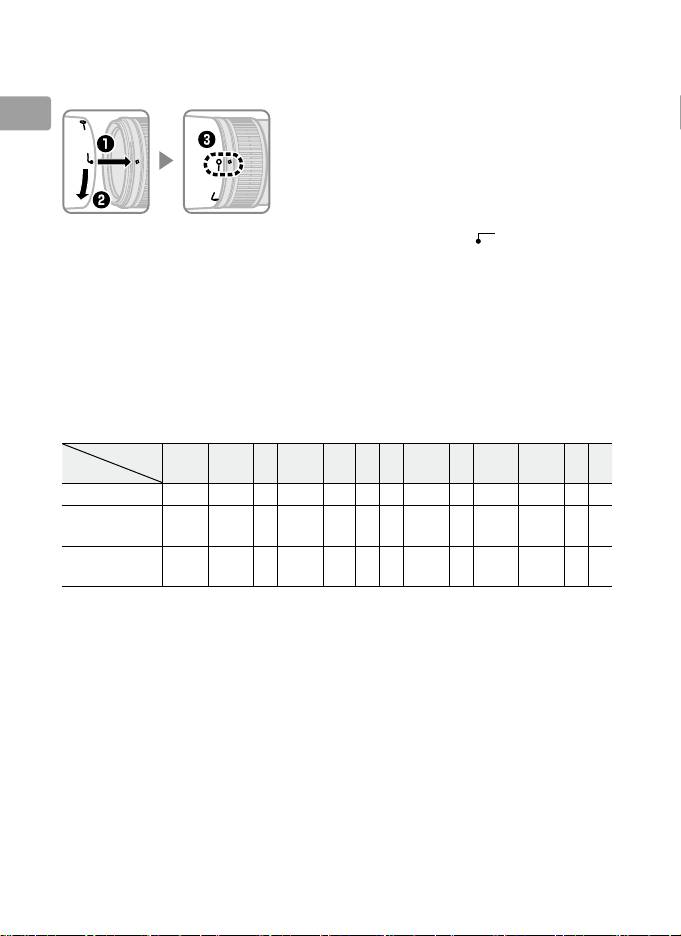
The Lens Hood
The lens hoods protect the lens and block stray light that would
otherwise cause flare or ghosting.
En
Align the lens hood lock mark (—) with the
lens hood mounting mark (●) on the lens (e).
When attaching or removing the hood, hold it near the symbol on its
base and avoid gripping it too tightly.
Vignetting may occur if the hood is
not correctly attached.
The hood can be reversed and mounted on the lens when not in use.
When the hood is reversed, it can be attached and removed by rotating it
while holding it near the lock mark (—).
■
Focusing Screens
The following cameras support a variety of focusing screens for use in
different situations.
Screen
EC‑B
Camera A B C E
EC‑E G1 G2 G3 G4 J L M U
F6
—
— — — — —
F5+DP-30
(+0.5)
F5+DA-30
(+1.0)
(+0.5)
(+0.5)
(–1.0)
(+0.5)
(+1.0)
: Recommended.
: Vignetting visible in viewfinder (photographs are not affected).
—: Not compatible with camera.
( ): Figures in parentheses give the exposure compensation for center-
weighted metering.
Select “Other screen” for Custom Setting b6
(“Screen comp.”) when adjusting exposure compensation for the F6;
note that with screens other than B or E, “Other screen” must be
selected even when the value for exposure compensation is 0.
Exposure compensation for the F5 can be adjusted using Custom
Setting 18; see the camera manual for details.
Empty cell: Not suited to use with this lens.
Note that type M screens can
however be used for photomicrography and macro photography at
magnifications of 1 : 1 or higher.
Note: The F5 supports matrix metering with A, B, E, EC-B/EC-E, J, and L
18
focusing screens only.
En_03
The Optional RT-1 Tripod Collar Ring
Loosen the tripod collar ring attachment knob to rotate the camera to the
desired position and orient the display horizontally or vertically. Note that
your hand may come into contact with the tripod if you rotate the camera
En
while holding it by the handgrip. Depending on how the camera or
tripod is attached, camera shake may be reduced by attaching the tripod
to the camera tripod mount.
A
WARNING
Fully tighten the tripod collar ring attachment knob when attaching
tripod collar ring.
Failure to observe this precaution could result in the
tripod collar ring becoming detached from the lens, causing injury.
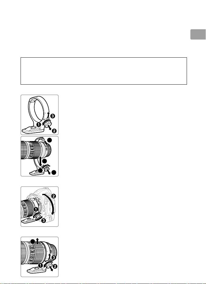
Attaching the Tripod Collar Ring
19
En_03
6
4
7
5
z
Loosen the tripod collar ring attachment knob
(q).
x
Open the ring.
Pull the attachment knob toward you (w) and
open the ring (e).
c
Place the lens in the ring (r).
v
Close the ring.
Pull the attachment knob toward you (t) and close
the ring (y).
Do not use excessive force, as your
hand could be caught in the ring.
b
Tighten the attachment knob (u).
Positioning the Camera
Loosen the attachment knob (q), adjust the position
indices to the desired vertical or horizontal orientation
(w), and then tighten the attachment knob (e).
Removing the Tripod Collar Ring
4
■
z
Loosen the attachment knob (q).
x
Remove the ring.
Pulling the attachment knob toward you (w), open
(e) and remove the lens (r).

■
Lens Care
•
Do not pick up or hold the lens or camera using only the lens hood.
•
Keep the CPU contacts clean.
En
•
Should the rubber lens‑mount gasket be damaged, cease use
immediately and take the lens to a Nikon‑authorized service center for
repair.
•
Use a blower to remove dust and lint from the lens surfaces.
To remove
smudges and fingerprints, apply a small amount of ethanol or lens
cleaner to a soft, clean cotton cloth or lens‑cleaning tissue and clean
from the center outwards using a circular motion, taking care not to
leave smears or touch the glass with your fingers.
•
Never use organic solvents such as paint thinner or benzene to clean
the lens.
•
The lens hood or NC filters can be used to protect the front lens
element.
•
Attach the front and rear caps before placing the lens in its flexible
pouch.
•
If the lens will not be used for an extended period, store it in a cool, dry
location to prevent mold and rust.
Do not store in direct sunlight or
with naphtha or camphor moth balls.
•
Keep the lens dry.
Rusting of the internal mechanism can cause
irreparable damage.
•
Leaving the lens in extremely hot locations could damage or warp parts
made from reinforced plastic.
■
Supplied Accessories
•
67 mm snap‑on Front Lens Cap LC‑67
•
Rear Lens Cap LF‑4
•
Bayonet Hood HB‑60
•
Flexible Lens Pouch CL‑1225
■
Compatible Accessories
•
67 mm screw‑on filters
•
Tripod collar ring RT‑1
•
AF‑I/AF‑S Teleconverters TC‑14E/TC‑14E II/TC‑17E II */TC‑20E */
TC‑20E II */TC‑20E III *
*
Autofocus is available only with cameras that offer f/8 support.
20
En_03

■
Specifications
Type Type G AF-S lens with built-in CPU and F mount
Focal length 70 – 200 mm
En
Maximum aperture f/4
Lens construction 20 elements in 14 groups (including 3 ED lens elements and lens
elements with Nano-Crystal coatings)
Angle of view
•
Nikon film SLR and FX‑format D‑SLR cameras: 34° 20′ – 12° 20′
•
Nikon DX‑format D‑SLR cameras: 22° 50′ – 8°
•
IX240 system cameras: 27° 40′ – 9° 50′
Focal length scale Graduated in millimeters (70, 85, 105, 135, 200)
Distance information Output to camera
Zoom Manual zoom using independent zoom ring
Focusing Nikon Internal Focusing (IF) System with autofocus
controlled by Silent Wave Motor and separate focus ring
for manual focus
Vibration reduction Lens shift using voice coil motors (VCMs)
Focus distance
1 m to infinity (∞)
indicator
Minimum focus
1 m (3.28 ft) from focal plane at all zoom positions
distance
Diaphragm blades 9 (rounded diaphragm opening)
Diaphragm Fully automatic
Aperture range f/4 to f/32
Metering Full aperture
Focus limit switch Two positions: FULL (∞ – 1 m) and ∞ – 3 m
Filter‑attachment size 67 mm (P = 0.75 mm
)
Dimensions Approx. 78 mm maximum diameter × 178.5 mm (distance
from camera lens mount flange)
Weight Approx. 850 g (30.0 oz)
Nikon reserves the right to change the specifications of the hardware
described in this manual at any time and without prior notice.
21
En_03
