Gorenje OGB80SEDDSB6: инструкция
Раздел: Бытовая, кухонная техника, электроника и оборудование
Тип: Водонагреватель
Характеристики, спецификации
Инструкция к Водонагревателю Gorenje OGB80SEDDSB6
OGB 30-120 SEDD/UNI

2

Navodila za uporabo 4
Instructions for Use 10
Gebrauchsanweisung 16
Руководство по зксплуатации 23
Інструкція з експлуатації 29
Upute za upotrebu 35
Упaтства за употребa 41
Návod k obsluze 48
Упaтства за употребу 54
Upute za upotrebu 60
Udhëzime për përdorim 66
Instrucţiuni de utilizare 72
Návod na obsluhu 78
Bruksanvisning 84
Manual del Usuario y del Instalador 90
Manual do instalador 96
Notice d’utilisation 102
Gebruiksaanwijzing 108
3
Cenjeni kupec, zahvaljujemo se Vam za nakup našega izdelka.
PROSIMO, DA PRED VGRADNJO IN PRVO UPORABO GRELNIKA VODE SKRBNO
PREBERETE NAVODILA.
SLO
APARAT NI NAMENJEN UPORABI OSEBAM (UPOŠTEVAJOČ TUDI OTROKE)
Z ZMANJŠANIMI FIZIČNIMI, ČUTNIMI ALI MENTALIMI SPOSOBNOSTMI ALI S
POMANKANJEM ISKUŠENJ OZ. ZNANJEM RAZEN, ČE SO POD NADZOROM ALI
POUČENI GLEDE UPORABE, S STRANI OSEBE ODGOVORNE ZA NJIHOVO VARNOST.
OTROCI MORAJO BITI POD NADZOROM, DA BI PREPREČILI, DA SE NE IGRAJO Z
NAPRAVO.
Grelnik je izdelan v skladu z veljavnimi standardi in uradno preizkušen, zanj pa sta bila
izdana tudi varnostni certikat in certikat o elektromagnetni kompatibilnosti. Njegove
osnovne tehnične lastnosti so navedene na napisni tablici, nalepljeni med priključnima
cevema. Grelnik sme priključiti na vodovodno in električno omrežje le za to usposobljen
strokovnjak. Posege v njegovo notranjost zaradi popravila, odstranitve vodnega kamna ter
preverjanja ali zamenjave protikorozijske zaščitne anode lahko opravi samo pooblaščena
servisna služba.
VGRADITEV
Grelnik vgradite čim bližje odjemnim mestom. Če boste grelnik vgradili v prostor, kjer
se nahaja kopalna kad ali prha, je potrebno obvezno upoštevati zahteve standarda IEC
60364-7-701 (VDE 0100, Teil 701). Na steno ga pritrdite s stenskima vijakoma nominalnega
premera minimalno 8 mm. Steno s slabo nosilnostjo morate na mestu, kamor ga boste
obesili, primerno ojačati. Grelnik smete pritrditi na steno samo pokončno.
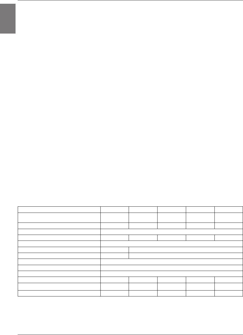
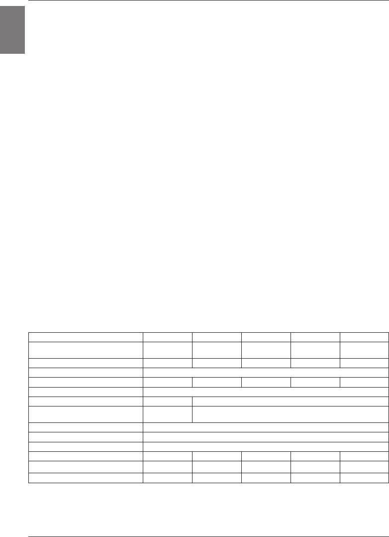
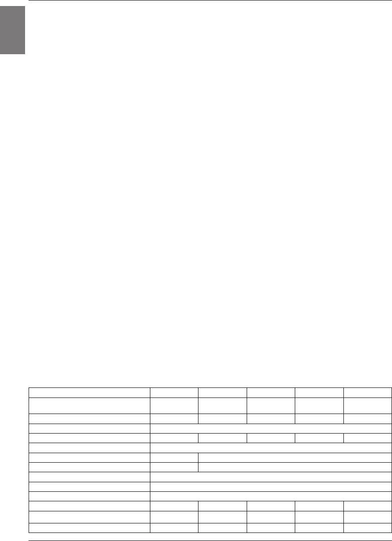
TEHNIČNE LASTNOSTI APARATA
Tip OGB 30 E3 OGB 50 E3 OGB 80 E3 OGB 100 E3 OGB 120 E3
OGB 30 SEDD/
OGB 50 SEDD/
OGB 80 SEDD/
OGB 100 SEDD/
OGB 120 SEDD/
Model
UNI
UNI
UNI
UNI
UNI
Prostornina [l] 30 50 80 100 120
Nazivni tlak [MPa] 0,6
Masa / napolnjen z vodo [kg] 19/49 24/74 31/111 36/136 41/161
Protikorozijska zaščita kotla Emajlirano / Mg anoda
Moč električnega grelca [W] 2100 2000
Število in moč grelcev [W] 3 x 700 2 x 1000
Priključna napetost [V~] 230
Razred zaščite I
Stopnja zaščite IP24
Čas segrevanja do 75°C
1)
[h] 1
05
1
55
3
05
3
55
4
35
Količina mešane vode pri 40°C [l] 54 96 151 199 238
Energijska poraba
2)
[kWh/24h] 0,69 0,94 1,30 1,54 1,79
1) Čas segrevanja celotne prostornine grelnika z električnim grelcem pri vstopni temperaturi hladne
vode iz vodovoda 15°C.
2) Energijska poraba pri vzdrževanju stalne temperature vode v grelniku 65°C in pri temperaturi okolice
20°C, merjeno po EN 60379.
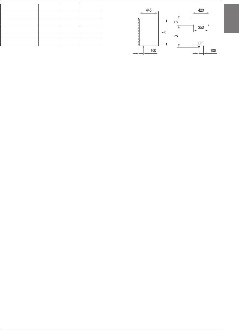
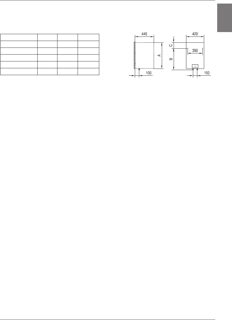
4

A B C
OGB 30 SEDD 510 310 235
OGB 50 SEDD 690 470 250
SLO
OGB 80 SEDD 950 735 245
OGB 100 SEDD 1125 900 255
OGB 120 SEDD 1300 900 430
Priključne in montažne mere grelnika [mm]
PRIKLJUČITEV NA VODOVODNO OMREŽJE
Dovod in odvod vode sta na ceveh grelnika barvno označena. Dovod hladne vode je označen
modro, odvod tople vode pa rdeče.
Grelnik lahko priključite na vodovodno omrežje na dva načina. Zaprti, tlačni sistem priključitve
omogoča odjem vode na več odjemnih mestih, odprti, netlačni sistem pa dovoljuje samo eno
odjemno mesto. Glede na izbrani sistem priključitve morate nabaviti tudi ustrezne mešalne
baterije.
Pri odprtem, netlačnem sistemu je treba pred grelnik vgraditi protipovratni ventil, ki preprečuje
iztekanje vode iz kotla, če v omrežju zmanjka vode. Pri tem sistemu priključitve morate
uporabiti pretočno mešalno baterijo. V grelniku se zaradi segrevanja prostornina vode
povečuje, to pa povzroči kapljanje iz cevi mešalne baterije. Z močnim zategovanjem ročaja
na mešalni bateriji kapljanja vode ne morete preprečiti, temveč lahko baterijo le pokvarite.
Pri zaprtem, tlačnem sistemu priključitve morate na odjemnih mestih uporabiti tlačne mešalne
baterije. Na dotočno cev je zaradi varnosti delovanja obvezno treba vgraditi varnostni ventil
ali varnostno grupo, ki preprečuje zvišanje tlaka v kotlu za več kot 0,1 MPa nad nominalnim.
Iztočna odprtina na varnostnem ventilu mora imeti obvezno izhod za atmosferski tlak.
Pri segrevanju vode v grelniku se tlak vode v kotlu zvišuje do meje, ki je nastavljena v
varnostnem ventilu. Ker je vračanje v ode nazaj v vodovodno omrežje preprečeno, lahko
pride do kapljanja vode iz odtočne odprtine varnostnega ventila. Kapljajočo vodo lahko
speljete v odtok preko lovilnega nastavka, ki ga namestite pod varnostni ventil. Odtočna
cev nameščena pod izpustom varnostnega ventila mora biti nameščena v smeri naravnost
navzdol in v okolju, kjer ne zmrzuje.
V primeru, da zaradi neustrezno izvedene inštalacije nimate možnosti, da bi kapljajočo vodo
iz povratnega varnostnega ventila speljali v odtok, se lahko kapljanju izognete z vgradnjo
ekspanzijske posode volumna 3 l na dotočni cevi grelnika.
Za pravilno delovanje varnostnega ventila morate sami periodično izvajati kontrole. Ob
preverjanju morate s premikom ročke ali odvitjem matice ventila (odvisno od tipa ventila)
odpreti iztok iz povratnega varnostnega ventila. Pri tem mora priteči skozi iztočno šobo
ventila voda, kar je znak, da je ventil brezhiben.
5

SLO
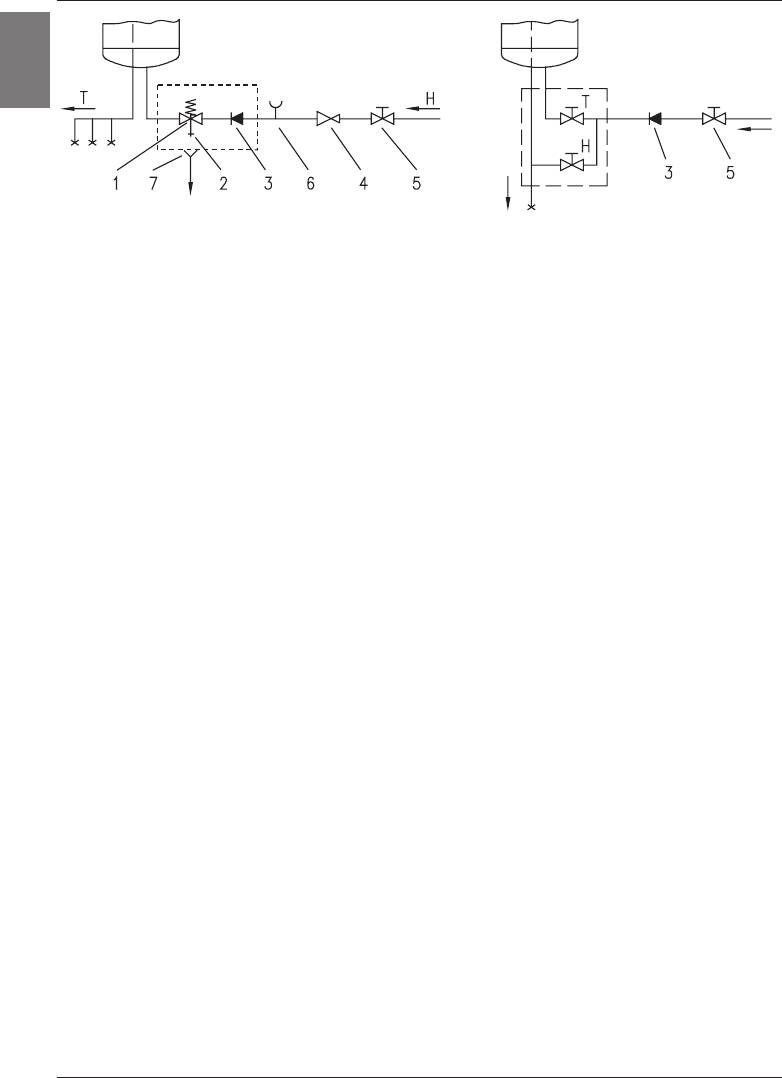
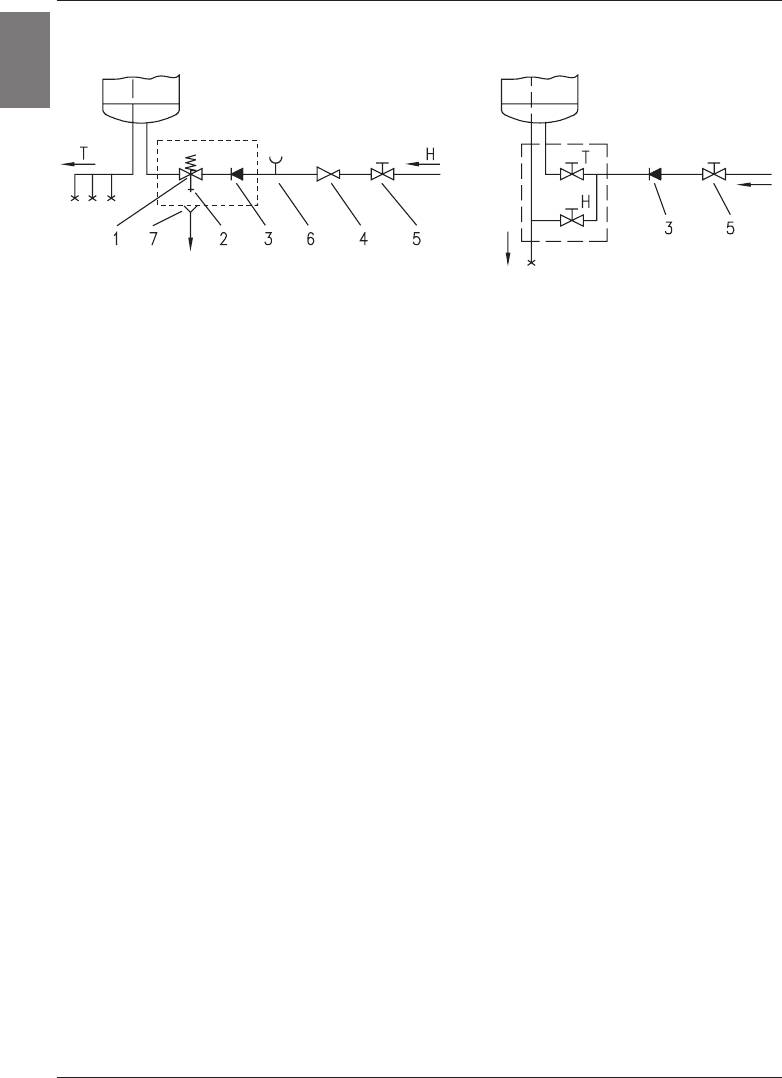
Zaprti (tlačni) sistem Odprti (netlačni) sistem
Legenda:
1 - Varnostni ventil 6 - Preizkusni nastavek
2 - Preizkusni ventil 7 - Lijak s priključkom na odtok
3 - Nepovratni ventil
4 - Redukcijski ventil tlaka H - Hladna voda
5 - Zaporni ventil T - Topla voda
Med grelnik in povratni varnostni ventil ne smete vgraditi zapornega ventila, ker bi s
tem delovanje povratnega varnostnega ventila onemogočili.
Grelnik lahko priključite na hišno vodovodno omrežje brez redukcijskega ventila, če je tlak
v omrežju nižji od 0,5 MPa (5 bar). Če tlak v omrežju presega 0,5 MPa (5 bar), morate
obvezno vgraditi redukcijski ventil.
Pred električno priključitvijo morate grelnik obvezno najprej napolniti z vodo. Pri prvi polnitvi
odprete ročico za toplo vodo na mešalni bateriji. Grelnik je napolnjen, ko voda priteče skozi
izlivno cev mešalne baterije.
PRIKLJUČITEV NA ELEKTRIČNO OMREŽJE
Pred priključitvijo v električno omrežje je potrebno v grelnik vgraditi priključno vrvico
2
2
minimalnega preseka vsaj 1,5 mm
(H05VV-F 3G 1,5 mm
). Da to lahko storite, morate z
grelnika odviti zaščitni pokrov.
Priključitev grelnika na električno omrežje mora potekati v skladu s standardi za električne
napeljave. Med grelnikom vode in trajno inštalacijo mora biti vgrajena priprava za ločitev
vseh polov od električnega omrežja v skladu z nacionalnimi inštalacijskimi predpisi.
6
SL
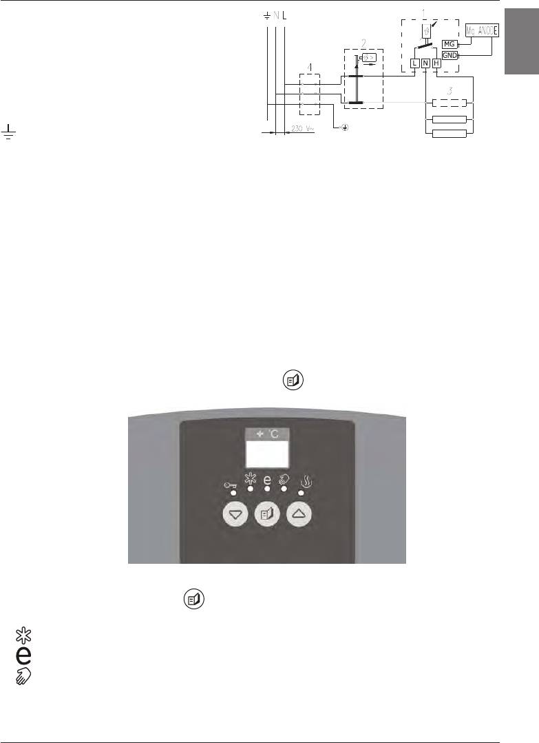
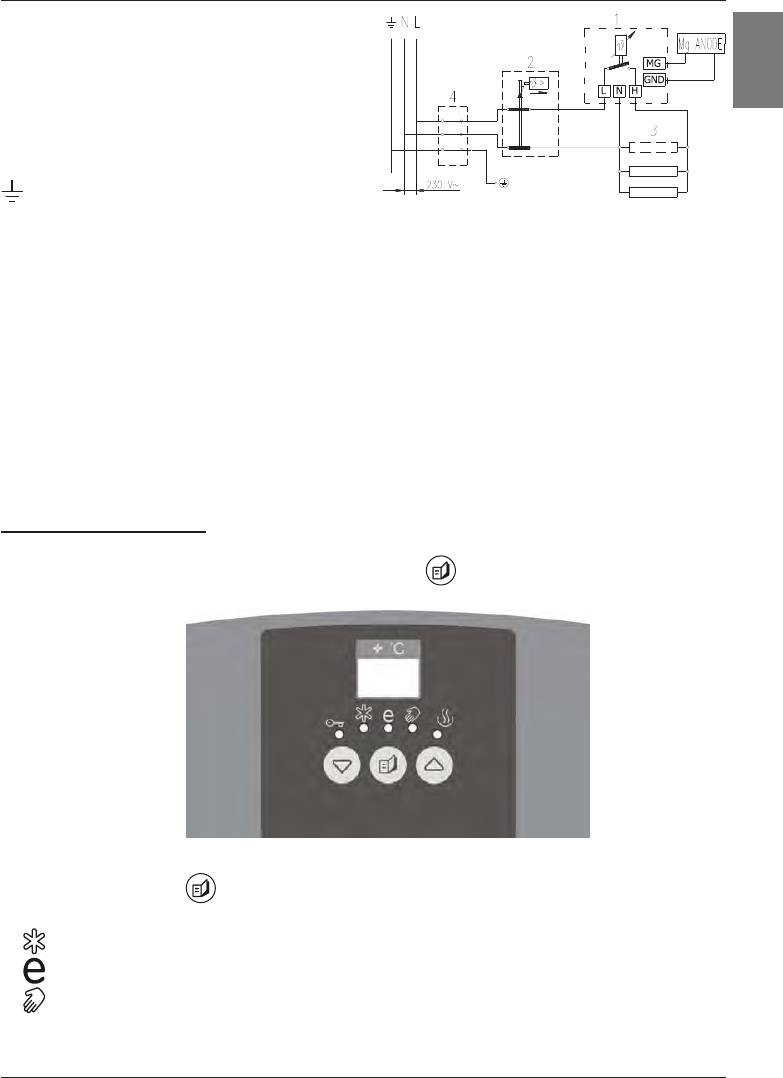
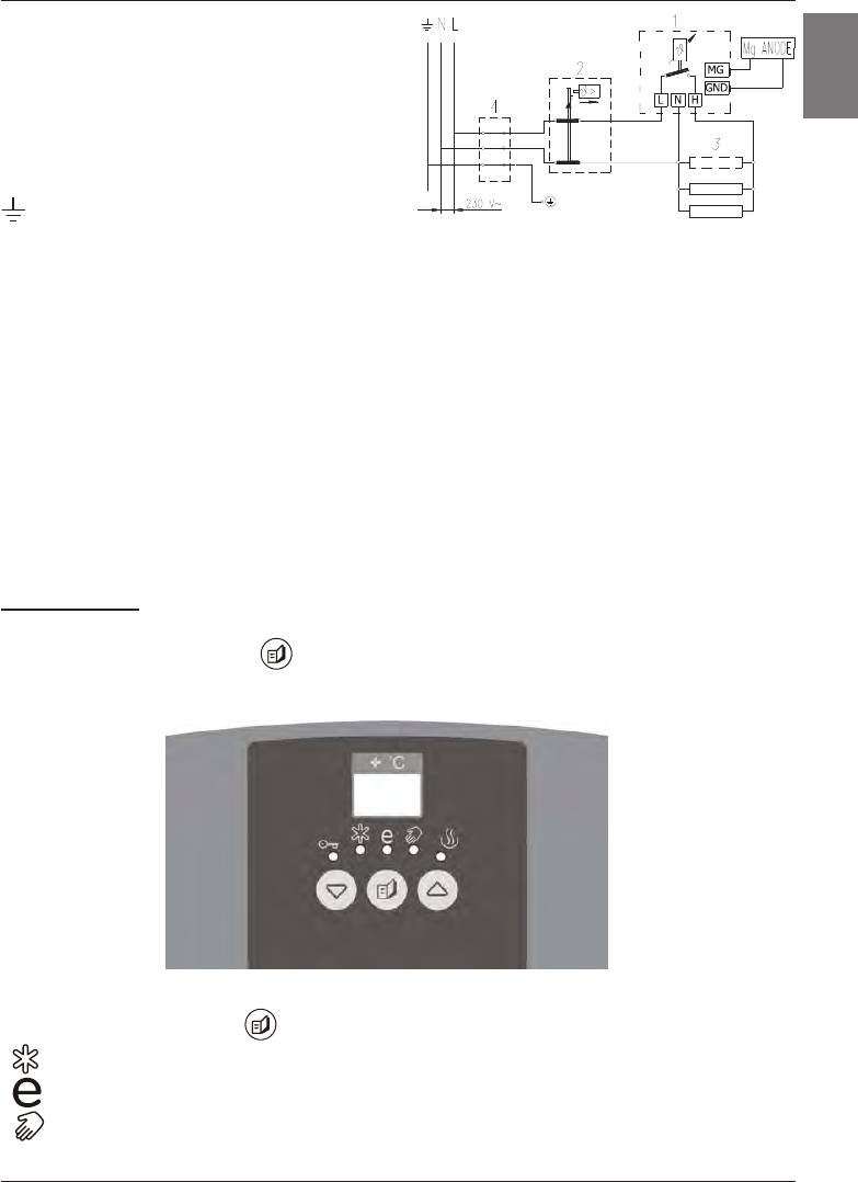
Legenda:
1 - Elektronski termostat
2 - Dvopolna toplotna varovalka
SLO
3 - Grelo (2x1000 W ali 3x700 W)
4 - Priključna sponka
L - Fazni vodnik
N - Nevtralni vodnik
- Zaščitni vodnik
Shema električne vezave
OPOZORILO: Pred vsakim posegom v njegovo notranjost morate grelnik obvezno
izključiti iz električnega omrežja!
UPORABA IN VZDRŽEVANJE
Po priključitvi na vodovodno in električno omrežje je grelnik pripravljen za uporabo.
Grelnik je opremljen z elektronskim regulatorjem, ki omogoča nastavitev temperature vode
v kotlu grelnika vode. Možna je ročna nastavitev želene temperature v območju od 35ºC
do 75ºC, nastavitev na ekonomično temperaturo in nastavitev na temperaturo zaščite proti
zamrzovanju vode v grelniku.
Elektronski regulator na prikazovalniku vseskozi kaže trenutno temperaturo vode v grelniku.
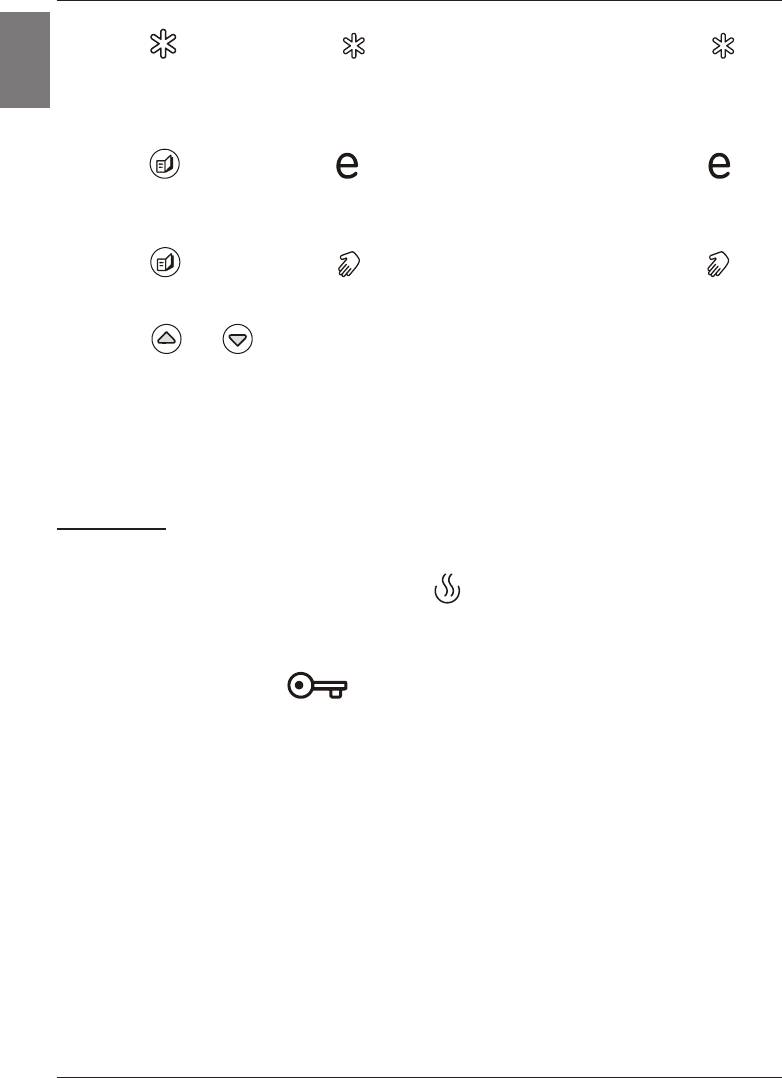
UPRAVLJANJE:
Vklop ali izklop grelnika opravimo s pritiskom tipke
daljšim od 2s.
S pritiskanjem programske tipke izbiramo med tremi možnostmi:
- izbira zaščite pred zamrzovanjem vode (prednastavljena temperatura vode na 7ºC)
- izbira ekonomične temperature (prednastavljeno na 55ºC)
- poljubna ročna nastavitev temperature v območju od 35ºC do 75ºC, s korakom 1ºC
7
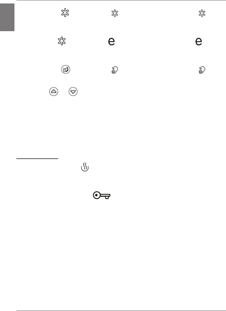
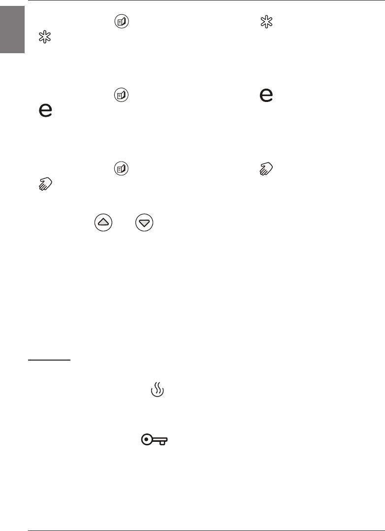
Nastavitev zaščite proti zamrzovanju:
- z menijsko tipko smo izbrali način (sveti rumena kontrolna lučka pod )
SLO
- s tem smo nastavili regulator na temperaturo 7ºC, kar nam kaže tudi prikazovalnik
Nastavitev na ekonomično temperaturo:
- z menijsko tipko
smo izbrali način (sveti rumena kontrolna lučka pod )
- s tem smo nastavili regulator na temperaturo 55ºC, kar nam kaže tudi prikazovalnik
Ročna nastavitev temperature:
- z menijsko tipko smo izbrali način (sveti rumena kontrolna lučka pod )
- na prikazovalniku se vedno prikaže zadnja nastavljena temperatura vode, razen ob prvem
zagonu, kadar se prikaže prednastavljena temperatura 35ºC
- s tipkama ali izberemo novo željeno temperaturo. S pritiskanjem tipke se
temperatura povečuje/zmanjšuje za 1ºC. Z držanjem tipke pa nastavitev pohitrimo.
- po končani nastavitvi željene temperature, prikazovalnik 3 sekunde utripa, ter se vrne v
prikaz trenutne temperature
- ob izpadu napajalne napetosti se aparat vrne v nastavljeno stanje pred izpadom napajanja
Vklop/izklop grelnika:
- če boste grelnik iz električnega omrežja izklopili, morate ob nevarnosti zamrznitve vodo iz
njega iztočiti
SIGNALIZACIJA:
• s kontrolnimi lučkami:
- delovanje grela : z zeleno kontrolno lučko, in sicer:
- grelo deluje – kontrolna lučka sveti
- grelo ne deluje – kontrolna lučka ne sveti
- delovanje Mg anode : z rdečo kontrolno lučko, in sicer:
- kontrolna lučka ne sveti – anoda deluje
- kontrolna lučka sveti - anoda je morda iztrošena
Opozorilo! Pri daljši neuporabi grelnika lahko signalna lučka
prikažeizrabljenostMganodekljubtemu,dajeMganodadobra.
Vtakšnemprimeruodpriteročicotoplevodenamešalnibateriji
(dotoksveževodevgrelnik).Česignalnalučkazaizrabljenost
anodeugasne,potemjegrelnikvredu.Vnasprotnemobvestite
pooblaščenoservisnoslužbo.
- delovanje grelnika: z rumeno kontrolno lučko, in sicer:
- zaščita proti zamrzovanju – kontrolna lučka sveti ali
- ekonomična temperatura – kontrolna lučka sveti ali
- ročna nastavitev – kontrolna lučka sveti
8

• z LED prikazovalnikom:
- temperatura vode v grelniku: od 0ºC do 75ºC
- ob nastavitvi prikaz nastavljene temperature: utripajoče od 0ºC do 75ºC
SLO
- indikacija napak:
- prikaz E1 - odpoved tipala elektronskega regulatorja (grelo ne deluje)
- prikaz E2 - odpoved tipala termometra (grelnik deluje)
- prikaz E3 - odpoved obeh tipal (grelnik ne deluje)
- prikaz E4 - nizka temperatura, zamrznitev (grelnik ne deluje)
- prikaz E5 - pregrevanje (temperatura > 100ºC) – (odpoved elektronskega
regulatorja)
Če grelnika ne mislite uporabljati dalj časa, zavarujete njegovo vsebino pred zmrznitvijo
na ta način, da elektrike ne izklopite, gumb termostata pa nastavite na položaj “*”. Pri tej
nastavitvi bo grelnik vzdrževal temperaturo vode približno na 10°C. Če boste grelnik iz
električnega omrežja izklopili, morate ob nevarnosti zmrznitve vodo iz njega iztočiti. Voda iz
grelnika se izprazni skozi dotočno cev grelnika. V ta namen je priporočljivo ob vgradnji med
varnostni ventil in dotočno cev namestiti poseben ting (T-člen) ali izpustni ventil. Grelnik
lahko izpraznite tudi neposredno skozi varnostni ventil s pomikom ročice oziroma s pomikom
vrtljive kapice v položaj kot pri preverjanju delovanja. Pred izpraznjenjem je grelnik potrebno
izključiti iz električnega omrežja in nato odpreti ročico za toplo vodo na priključeni mešalni
bateriji. Po izpraznitvi vode skozi dotočno cev, v grelniku ostane manjša količina vode, ki
izteče skozi odprtino grelne prirobnice ob odstranitvi grelne prirobnice.
Zunanjost grelnika čistite z blago raztopino pralnega praška. Ne uporabljajte razredčil in
grobih čistilnih sredstev.
Z rednimi servisnimi pregledi boste zagotovili brezhibno delovanje in dolgo življenjsko dobo
grelnika. Garancija za prerjavenje kotla velja le, če ste izvajali predpisane redne preglede
izrabljenosti zaščitne anode. Obdobje, med posameznimi rednimi pregledi, ne sme biti
daljše od 36 mesecev. Pregledi morajo biti izvedeni s strani pooblaščenega serviserja, ki
Vam pregled evidentira na garancijskem listu proizvoda. Ob pregledu preveri izrabljenost
protikorozijske zaščitne anode in po potrebi očisti vodni kamen, ki se glede na kakovost,
količino in temperaturo porabljene vode nabere v notranjosti grelnika. Servisna služba
vam bo po pregledu grelnika glede na ugotovljeno stanje priporočila tudi datum naslednje
kontrole.
Prosimo Vas, da morebitnih okvar na grelniku ne popravljate sami, ampak o njih
obvestite najbližjo pooblaščeno servisno službo.
9
Dear buyer, we thank you for purchase of our product.
Prior to installation and rst use of the electric water heater, please carefully read
these instructions.
EN
THIS APPLIANCE IS NOT INTENDED FOR USE BY PERSONS (INCLUDING CHILDREN)
WITH REDUCED PHYSICAL, SENSORY OR MENTAL CAPABILITIES, OR LACK OF
EXPERIANCE AND KNOWLEDGE, UNLESS THEY HAVE BEEN GIVEN SUPERVISION
OR INSTRUCTION CONCERNING USE OF THE APPLIANCE BY PERSON RESPONSIBLE
FOR THEIR SAFETY.
CHILDREN SHOULD BE SUPERVISED TO ENSURE THAT THEY DO NOT PLAY WITH
THE APPLIANCE.
This water heater has been manufactured in compliance with the relevant standards
and tested by the relevant authorities as indicated by the Safety Certicate and the
Electromagnetic Compatibility Certicate. The technical characteristics of the product are
listed on the label afxed between the inlet and outlet pipes. The installation must be carried
out by qualied staff. All repairs and maintenance work within the water heater, e.g. lime
removal or inspection/replacement of the protective anticorrosion anode, must be carried out
by the authorised maintenance service provider.
BUILDING-IN
The water heater shall be built-in as close as possible to the outlets. When installing the
water heater in a room with bathtub or shower, take into account requirements dened in IEC
Standard 60364-7-701 (VDE 0100, Part 701). It has to be tted to the wall using appropriate
rag bolts with minimum diameter of 8 mm. The wall with feeble charging ability must be on
the spot where the water heater shall be hanged suitably reinforced. The water heater may
be xed upon the wall only vertically.
TECHNICAL PROPERTIES OF THE APPLIANCE
Type OGB 30 E3 OGB 50 E3 OGB 80 E3 OGB 100 E3 OGB 120 E3
OGB 30 SEDD/
OGB 50 SEDD/
OGB 80 SEDD/
OGB 100 SEDD/
OGB 120 SEDD/
Model
UNI
UNI
UNI
UNI
UNI
Volume [l] 30 50 80 100 120
Rated pressure [MPa] 0,6
Weight / Filled with water [kg] 19/49 24/74 31/111 36/136 41/161
Anti-corrosion of tank Emailed & Mg Anode
Power of electrical heater [W] 2100 2000
Number and power of heating
[W] 3 x 700 2 x 1000
elements
Connection voltage [V~] 230
Protection class I
Degree of protection IP24
Heating time to 75 °C
1)
[h] 1
05
1
55
3
05
3
55
4
35
Quantity of mixed at 40°C [l] 54 96 151 199 238
Energy consumption
2)
[kWh/24h] 0,69 0,94 1,30 1,54 1,79
1) Time for heating of the whole volume of heater with electric immersion heater by entering temperature
of cold water from water supply 15°C.
2) Energy consumption to maintain stable temperature of water in the water heater 65°C at surrounding
temperature 20°C, measured according to EN 60379.
10
A B C
OGB 30 SEDD 510 310 235
OGB 50 SEDD 690 470 250
EN
OGB 80 SEDD 950 735 245
OGB 100 SEDD 1125 900 255
OGB 120 SEDD 1300 900 430
Connection and installation dimensions of the water heater [mm]
CONNECTION TO THE WATER SUPPLY
The water heater connections for the in-owing and out-owing water are colour-coded. The
connection for the supply of cold water is coloured blue, while the hot water outlet is coloured
red.
The water heater may be connected to the water supply in two ways. The closed-circuit
pressure system enables several points of use, while the open-circuit gravity system enables
a single point of use only. The mixer taps must also be purchased in accordance with the
selected installation mode.
The open-circuit gravity system requires the installation of a non-return valve in order to
prevent the water from draining out of the tank in the event of the water supply running dry
or being shut down. This installation mode requires the use of an instantaneous mixer tap.
As the heating of water expands its volume, this causes the tap to drip. The dripping cannot
be stopped by tightening it further; on the contrary, the tightening can only damage the tap.
The closed-circuit pressure system requires the use of pressure mixer taps. For safety
reasons the supply pipe must be tted with a return safety valve or alternatively, a valve of
the safety class that prevents the pressure in the tank from exceeding the nominal pressure
by more than 0.1 MPa. The outlet opening on the relief valve must be equipped with an outlet
for atmospheric pressure.
The heating of water in the heater causes the pressure in the tank to increase to the level set
by the safety valve. As the water cannot return to the water supply system, this can result in
the dripping from the outlet of the safety valve. The drip can be piped to the drain by installing
a catching unit just below the safety valve. The drain installed below the safety valve outlet
must be piped down vertically and located in the environment that is free from the onset of
freezing conditions.
In case the existing plumbing does not enable you to pipe the dripping water from the return
safety valve into the drain, you can avoid the dripping by installing a 3-litre expansion tank
on the inlet water pipe of the boiler.
In order to provide correct operation of the relief valve, periodical inspections of the relief
valve must be carried out by the user. To check the valve, you should open the outlet of the
return safety valve by turning the handle or unscrewing the nut of the valve (depending on
the type of the valve). The valve is operating properly if the water comes out of the nozzle
when the outlet is open.
11
Closed (pressure) system Open (non-pressure) system
Legend:
1 - Safety valve 6 - Checking tting
2 - Test valve 7 - Funnel with outlet connection
3 - Non-return valve
4 - Pressure reduction valve H - Cold water
5 - Closing valve T - Hot water
Between the water heater and return safety valve no closing valve may be built-in
because with it the function of return safety valve would be impeded.
The water heater may be connected to the water network in the house without reduction
valve if the pressure in the network is lower than 0.5 MPa (5 bar). If the pressure exceeds
0.5 MPa (5 bar), a reduction valve must be installed. Prior to the electric connection the
water heater must obligatorily be lled with water. By rst lling the tap for the hot water upon
the mixing tap must be opened. When the heater is lled with water, the water starts to run
through the outlet pipe of the mixing tap.
CONNECTION OF THE WATER HEATER TO THE ELECTRIC NETWORK
Before connecting to power supply network, install a power supply cord in the water heater,
2
2
with a min. diameter of 1,5 mm
(H05VV-F 3G 1,5 mm
). For it the protection plate must be
removed from the water heater.
The connection of water heater to the electric network must be performed according to
standards for electric installation. Install a disconnect switch (separating all poles from the
power supply network) between the water heater and the permanent power connection, in
compliance with the national regulations.
12
SL
EN
Legend:
1 - Electronic thermostat
2 - Bipolar thermal fuse
EN
2 - Electric heater (2x1000 W or 3x700 W)
4 - Connection terminal
L - Live conductor
N - Neutral conductor
- Earthing conductor
Electric installation
CAUTION: Prior to each reach in the inner of the water heater it must absolutely be
disconnected from the electric network!
OPERATION AND MAINTENANCE
After connecting to water and power supply, the heater is prepared for use.
The water heater features an that enables of water temperature of in water heater tank. The
electronic regulator allows manual adjustment of temperature in range from 35ºC to 75ºC,
settings to cost saving operation mode and temperature adjustment to prevent freezing.
Electronic regulator display shows the current temperature of water in water heater.
OPERATION CONTROL:
The heater is switched ON and OFF by pressing the
key for 2s.
Continue pressing the key and select the three operating modes:
- protection against freezing (factory water temperature set to 7ºC)
- cost saving operation (factory set to 55ºC)
- optional manual setting of temperature in the range from 35ºC to 75ºC (increments of
1ºC)
13
Protection against freezing:
- Use the key and select the operating mode (yellow control lamp under is on)
EN
- The regulator is set to temperature 7ºC – shown on the display
Cost saving operating mode:
- Use the key and select the operating mode (yellow control lamp under is on)
- The regulator is set to temperature 55ºC – shown on the display
Manual temperature setting:
- Use the key and select the operating mode (yellow control lamp under is on).
- The display always shows the last setting of the water temperature; except on rst turn on
of appliance when factory setting 35ºC is displayed.
- Use the or key to select new temperature. By pressing the key you increase/
decrease the temperature by 1ºC. Holding the key will speed up the process.
- After required temperature is set display ashes for 3 seconds and then shows the current
temperature again.
- In case of interruptions in power supply, the appliance resumes operating with the settings
adjusted before the interruption.
INDICATION:
• Control lamps:
- Heating element operation : Green control lamp:
- the heating element is on – the lamp is on
- the heating element is off – the lamp is off
- Mg anode : Red control lamp:
- the lamp is off – anode is active
- the lamp is on – anode may be worn out
Warning! Whenthewaterheaterisoutofuseforlonger
periodoftime,thesignallampmayindicatethattheMg
anodeiswornoutinspiteofthefactthattheMganode
isstillactive.Inthiscaseopenthehotwatertap(fresh
waterowintowaterheater).Ifthesignallampswitches
off,thewaterheateroperationisnotimpaired.Ifnot,call
thenearestauthorizedserviceprovider
- Water heater operation: Yellow control lamps:
- protection against freezing – the lamp is on or
- cost saving temperature setting – the lamp is on or
- manual setting– the lamp is on
14

• LED display:
- Water temperature of in the heater: from 0ºC to 75ºC
- When set, display of the adjusted temperature: (ashing from 0ºC to
EN
75ºC)
- Error indication:
- display E1 – failure of the electronic regulator sensor (the
heating element doesn’t operate)
- display E2 - failure of the thermometer sensor (water heater
operates)
- display E3 - failure of both sensors (water heater doesn’t
operate)
- display E4 – low temperature, freezing (water heater doesn’t
operate)
- display E5 – overheating (temperature > 100ºC) – (failure of
electronic regulator)
When the water heater is not in use for longer periods of time, it should be protected from
freezing by setting the temperature to “*”. Do not disconnect the power. Thus the temperature
of water is maintained at about 10°C. Should you choose to disconnect the power, the
water heater should be thoroughly drained before the onset of freezing conditions. Water is
discharged from heater via the inlet pipe. To this purpose, a special tting (T-tting) must be
mounted between the relief valve and the heater inlet pipe, or a discharge tap. The heater
can be discharged directly through the relief valve, by rotating the handle or the rotating
valve cap to same position as for checking the operation. Before discharge, make sure
the heater is disconnected from the power supply, open the hot water on the connected
mixer tap. After discharging through the inlet pipe, there is still some water left in the water
heater. The remaining water will be discharged after removing the heating ange, through
the heating ange opening.
The external parts of the water heater may be cleaned with a mild detergent solution. Do not
use solvents and abrasives.
Regular preventive maintenance inspections ensure faultless performance and long
life of your heater. The rst of these inspections should be carried out by the authorised
maintenance service provider about two years from installation in order to inspect the
wear of the protective anticorrosion anode and remove the lime coating and sediment as
required. The lime coating and sediment on the walls of the tank and on the heating element
is a product of quality, puantity and temperature of water owing through the water heater.
The maintenance service provider shall also issue a condition report and recommend the
approximate date of the next inspection.
Never try to repair any possible faults of the water heater by yourself, but inform
about it the nearest authorised service workshop.
15
Geehrter Käufer, wir danken Ihnen für die Anschaffung unseres Produktes.
WIR BITTEN SIE VOR DEM EINBAU UND VOR DEM ERSTEN GEBRAUCH DES
D
WARMWASSERBEREITERS SORGFÄLLTIG DIE ANWEISUNGEN DURCHZULESEN.
DIESES GERÄT IST NICHT FÜR DIE NUTZUNG DURCH PERSONEN (EINSCHLIEßLICH
KINDER) MIT EINGESCHRÄNKTER KÖRPERLICHEN, SENSORISCHEN ODER
GEISTIGEN FÄHIGKEITEN, ODER DAS FEHLEN VON ERFAHRUNG UND WISSEN,
SOFERN SIE NICHT ERHIELTEN ÜBERWACHUNG ODER BELEHRUNG ÜBER DIE
VERWENDUNG DES GERÄTS NACH PERSONEN, DIE FÜR IHRE SICHERHEIT.
KINDER SOLLTEN ÜBERWACHT WERDEN, UM SICHERZUSTELLEN, DASS SIE NICHT
SPIELEN, MIT DEM GERÄT.
Die Herstellung des Warmwasserbereiters erfolgte im Einklang mit den gültigen
Normen. Das Gerät wurde einer ordnungsgemäßen Prüfung unterzogen und mit einem
Sicherheitsnachweis und einem Zertikat über elektromagnetische Kompatibilität versehen.
Seine grundtechnische
Eigenschaften sind auf dem Anschriftstafelchen das zwischen den beiden Annschlussröhren
angeklebt ist. Den Warmwasserbereiter darf an das Wasser- und Elektronetz nur dafür
befähigter Fachmann anschliessen. Eingriffe in das innere wegen Reparatur, Beseitigung
des Wassersteines und Kontrolle oder Auswechselung der Antikorrosions -Schutzanode
darf nur bevollmächtigter Kundendienst ausführen.
EINBAU
Den Warmwasserbereiter montieren Sie möglichst nahe der Abnahmestelle. Bei der
Montage des Warmwasserspeichers im Raum, wo Badewanne oder Dusche stehen, sind
die Anforderungen des Standards IEC 60364-7-701 (VDE 0100, Teil 701) unbedingt zu
berücksichtigen. Das Gerät wird mittels zwei Wandschrauben mit Nominaldurchmesser von
mindestens 8 mm an die Wand befestigt. Den Warmwasserbereiter befestigen sie an die
Wand mit Wandschrauben.
Die Wand mit schwacher Tragfähigkeit müssen Sie an der Stelle, wo sie ihn aufhängen
werden, entsprechend verstärken. Den Warmwasserbereiter dürfen Sie nur senkrecht
befestigen.
TECHNISCHE DATEN DES GERÄTES
Typ OGB 30 E3 OGB 50 E3 OGB 80 E3 OGB 100 E3 OGB 120 E3
OGB 30 SEDD/
OGB 50 SEDD/
OGB 80 SEDD/
OGB 100 SEDD/
OGB 120 SEDD/
Model
UNI
UNI
UNI
UNI
UNI
Volumen [l] 30 50 80 100 120
Nenndruck [MPa] 0,6
Gewicht/gefüllt mit Wasser [kg] 19/49 24/74 31/111 36/136 41/161
Korrosionsschutz des Behälters emailliert & Magnesiumschutzanode
Zahl und Stärke der Heizkörper [W] 2100 2000
Število in moč grelcev [W] 3 x 700 2 x 1000
Anschlußspannung [V~] 230
Schutzklasse I
Grad des Apparatschutzes IP24
Aufwärmungszeit bis 75°C
1)
[h] 1
05
1
55
3
05
3
55
4
35
Mischwassermenge bei 40°C [l] 54 96 151 199 238
Bereitschaftsstromverbrauch
2)
[kWh/24h] 0,69 0,94 1,30 1,54 1,79
16
1) Diese Werte gelten für das Mischen des Wassers aus der Wasserleitung von ca. 15°C und des
Heisswassers aus dem Heisswasserspeicher bei einer Wassertemperatur von 65°C.
2) Bei 65°C Wassertemperatur gemessen (gemäss EN 60379).
D
A B C
OGB 30 SEDD 510 310 235
OGB 50 SEDD 690 470 250
OGB 80 SEDD 950 735 245
OGB 100 SEDD 1125 900 255
OGB 120 SEDD 1300 900 430
Die Einbaumaße [mm]
ANSCHLUSS AN DAS WASSERLEITUNGSNETZ
Die Wasseristallation muss gemäß DIN1988 durchgefürt werden. Zu-und Ableitung sind an
den Röhren des Warmwaserbereiters farbig gekennzeichnet. Zuleitung des kalten Wassers
ist blau, Ableitung des warmen Wassers ist aber rot. Den Warmwasserbereiter können Sie
an das Wasserleitungsnetz auf zwei Weisen anschliessen. Geschlossenes Drucksytem des
Anschlusses ermöglicht die Abnahme an mehreren Abnahmestellen, das ofene Drucklose
System aber erlaubt nur eine Abnahmestelle. Mit Hinsicht auf gewähltes Anschlussystem
müssen Sie auch entsprechende Mischbatterien anschaffen.
Bei offenem drucklosem System muss vor dem Warmwasserbereiter ein Rückschlagventil
eingebaut werden, das den Wasseeraususs aus den Kessel, wenn es im Wassernetz kein
Wasser gibt vermeidet. Bei diesem Anschlussystem müssen Sie eine Vorlauf Mischbatterie
verwenden.
Bei erwärmen vergrössert sich das Wasserwolumen was zu tropfen aus den Auslaufrohr der
Mischbaterie fürt. Wenn die eingestellte Wassertemperatur erreicht ist endet das tropfen. Mit
starkem Anziehen des Griffes an der Mischbatterie können Sie das Tröpfeln des Wassers nicht
verhindern, sondern Sie können die Batterie nur verderben. Bei geschlossenem Drucksystem
des Anschlusses müssen Sie an Abnahmestelle DruckMischbatterien verwenden. Für
eine sichere Betriebsweise ist unbedingt ein baumustergepruftes Sicherheitsventil an das
Zulaufrohr einzubauen oder eine Sicherheitsgruppe, die einen Druckanstieg von mehr als
0,1 MPa über Nominal im Kessel verhindert. Die Auslauföffnung am Sicherheitsventil muss
unbedingt den Ausgang zum Luftdruck haben.
Um die richtige Funktion des Sicherheitsventils zu gewährleisten, müssen Sie selber
periodische Kontrollen ausführen. Da der Wasserücklauf zurück in das Wasserleitungsnetz
verhindert ist kann es zum Tröpfeln des Wassers aus der Ablauföffnung des Sicherheitsventils
kommen. Das tröpfende Wasser können Sie in den Abusss über den Auffaaangsausatz den
Sie unter das Sicherheitsventil anbringen leiten. Das Ablussrohr, das unter dem Ablauf des
Sicherheitsventils angebracht wird, ist senkrecht nach unten und in frostfreier Umgebung
einzubauen.
Gibt es wegen einer unsachgemäß ausgeführten Installation keine Möglichkeit, das tropfende
Wasser aus dem Rückschlagventil in den Ablauf zu leiten, kann man das Tröpfeln vermeiden,
indem ein Expansionsgefäß mit dem Volumen 3 l am Zulaufrohr des Warmwasserbereiters
eingebaut wird.
Das Sicherheitsventil muss regelmäßig betrieben werden, um Kalkablagerungen zu
17
Das Drucksystem Das Durchußsystem
Legende:
1 - Sicherheitsventil 6 - Testansatzstück
2 - Testventil 7 - Trichter mit dem Anschluß
3 - Sperrventil an den Ablauf
4 - Reduzierdruckventil H - Kaltwasser
5 - Sperrventil T - Warmwasser
Zwischen dem Warmwasserbereiter und den Sicherheitsventil dürfen Sie kein
Absperrventil einbauen, weil Sie dadurch die Wirkung des Sicherheitsventils
verhindern.
Den Warmwasserbereiter können Sie an das Wasserleitungsnetz ohne Reduktionsventil
anschließen, wenn der Druck im Netz niedriger als 0,5 MPa (5 bar) ist. Ist der Druckwert
von 0,5 MPa (5 bar) überschritten, so muss ein Reduzierventil unbedingt eingebaut werden.
Vor dem elektrischen Anschluß müssen Sie den Warmwasserbereiter verbindlich zuerst
mit Wasser auffüllen. Bei erster Füllung öffnen Sie die Spindel für warmes Wasser auf der
Mischbatterie.
Der Warmwasserbereiter ist aufgefüllt, wann das Wasser durch das Ausußrohr der
Mischbatterie ießt.
ANSCHLUß AN DAS ELEKTRONETZ
Vor dem Anschluss an den elektrischen Stromkreis ist in den Warmwasserspeicher das
Anschlusskabel mit einem Mindestdurchmesser von 1,5 mm² (H05VV-F 3G 1,5 mm²)
einzubauen. Damit Sie das tun können, müssen Sie von dem Warmwasserbereiter den
Schutzdeckel abschrauben.
Der Anschluß des Warmwasserbereiters an das Elektronetz muß im Einklang mit den Normen
für elektrische Installation verlaufen. Zwischen Warmwasserspeicher und Dauerinstallation
muss eine Vorrichtung zur Trennung aller Pole vom Stromnetz im Einklang mit nationalen
Installationsvorschriften eingebaut werden.
Am Gehäuse des Warmwasserspeichers ist ein Bimetallthermometer angebracht, dessen
Zeiger sich von 0 aus im Uhrzeigersinn bewegt, wenn im Warmwasserspeicher das Wasser
heiß ist.
18
SL
entfernen un zum Überprüfen, dass es nich blockiert ist.
D
Legende:
1 - Thermostat
2 - mit zweipoligeThermosicherung
D
3 – Heizkörper (2x1000 W oder 3x700 W)
4 - Anschlußklemme
L - Phasen leiter
N - Neutralleiter
- Schutzleiter
Das Schaltungsschema des Elektroanschlusse
WARNUNG: Vor jedem Eingriff in das Innere des Gerätes, müssen sie den
Warmwasserbereiter unbedingt vom elektrischen Netz trennen.
ANWENDUNG UND WARTUNG
Nach Anschluss an das Wasser- und Stromnetz ist der Warmwasserbereiter betriebsbereit.
Der Heizkörper hat einen elektronischen Regler zur Einstellung der Wassertemperatur im
Kessel des Warmwasserbereiters. Die gewünschte Temperatur von 35º C bis 75º C, die
ökonomische Temperatur und die Gefrierschutztemperatur des Wassers im Kessel kann
auch von Hand eingestellt werden. An der Anzeige des elektronischen Reglers wird immer
die momentane Wassertemperatur im Warmwasserbereiter angezeigt.
BEDIENUNG:
Durch Betätigung der Taste länger als 2 s wird der Warmwasserbereiter ein- bzw.
ausgeschaltet.
Durch Betätigung der Taste wählt man unter drei Möglichkeiten:
-
Gefrierschutz (voreingestellte Wassertemperatur von 7º C)
-
ökonomische Temperatur (voreingestellt auf 55º C)
-
beliebige manuelle Einstellung der Temperatur im Bereich von 35º C bis 75º C, im
Schritt von 1º C.
19
Einstellung des Gefrierschutzes:
- Mit der Menütaste wählt man den Betriebszustand (gelbe Kontrollleuchte unter
leuchtet),
- dadurch wird auch der Regler auf die Temperatur 7º C eingestellt, was auch angezeigt
wird.
Einstellung der ökonomischen Temperatur:
- Mit der Menütaste wählt man den Betriebszustand (gelbe Kontrollleuchte unter
leuchtet),
- dadurch wird auch der Regler auf die Temperatur 55º C eingestellt, was auch angezeigt
wird.
Manuelle Temperatureinstellung:
- Mit der Menütaste wählt man den Betriebszustand (gelbe Kontrollleuchte unter
leuchtet)
- An der Anzeige wird immer die zuletzt eingestellte Wassertemperatur angezeigt, außer
bei der ersten Inbetriebnahme, wenn die voreingestellte 35º C angezeigt wird.
- Mit den Tasten oder wählen Sie die gewünschte Temperatur. Durch Betätigung
der entsprechenden Taste wird die Temperatur um 1º C erhöht oder reduziert. Durch
Halten der Taste wird die Einstellung der Temperatur beschleunigt.
- Nach beendeter Einstellung der gewünschten Temperatur blinkt die Anzeige 3 Sekunden,
und danach wird wieder die momentane Temperatur gezeigt.
- Beim Spannungsausfall geht das Gerät in den eingestellten Zustand vor dem
Spannungsausfall zurück.
Ein-/Ausschalten des Warmwasserbereiters:
- Vor dem Ausschalten des Warmwasserbereiters, muss bei Gefriergefahr das Wasser aus
dem Warmwasserbereiter ausgelassen werden.
ANZEIGE:
• mit Kontrollleuchten:
- Betrieb des Heizkörpers
20
: bei grüner Kontrollleuchte und zwar:
- Der Heizkörper ist in Betrieb – Kontrollleuchte leuchtet
- Der Heizkörper ist nicht in Betrieb – Kontrollleuchte leuchtet nicht
- Betrieb der Mg Anode
D
: bei roter Kontrollleuchte und zwar:
- Kontrollleuchte leuchtet nicht – die Anode ist aktiv
- Kontrollleuchte leuchtet – die Anode kann verbraucht sein
Warnung!WenndasWasser-HeizungistfürdieVerwendungvonlängerenZeitraum,der
Signalleuchtekanndaraufhindeuten,dassderMg-Anodeistverschlissen,trotzder
Tatsache,dassdieMg-Anodeistimmernochaktiv.IndiesemFallöffnenSiedasheiße
WasserLeitungswasser(SüßwasserießeninWasserkocher).WenndasSignalLampe


